Hirschmann RS20 User Manual
Redundancy configuration
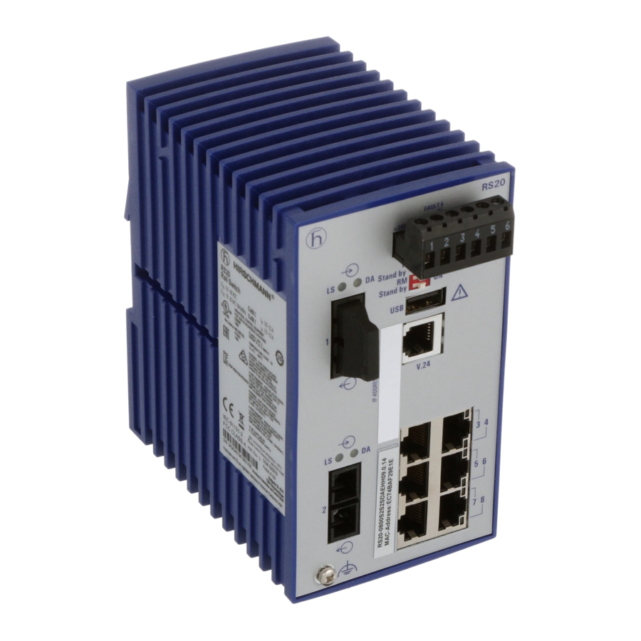
industrial ethernet (gigabit-)switch
Hide thumbs
Also See for RS20:
- Reference manual (572 pages) ,
- User manual (294 pages) ,
- Programming manual (116 pages)
Table of Contents
Advertisement
Quick Links
Advertisement
Table of Contents

Related Manuals for Hirschmann RS20


Summary of Contents for Hirschmann RS20
- Page 1 User Manual Redundancy Configuration Industrial ETHERNET (Gigabit-)Switch RS20/RS30/RS40, MS20/MS30, OCTOPUS, PowerMICE, RSR20/RSR30, MACH 100, MACH 1000, MACH 4000 UM RedundConfig L2P Technical Support Release 8.0 05/2013 https://hirschmann-support.belden.eu.com...
- Page 2 In addition, we refer to the conditions of use specified in the license contract. You can get the latest version of this manual on the Internet at the Hirschmann product site (www.hirschmann.com). Printed in Germany Hirschmann Automation and Control GmbH Stuttgarter Str.
-
Page 3: Table Of Contents
Contents Contents About this Manual Introduction Overview of Redundancy Topologies Overview of Redundancy Protocols Link Aggregation Example of link aggregation 2.1.1 Creating and configuring the link aggregation HIPER-Ring and Link Aggregation Ring Redundancy Example of a HIPER-Ring 3.1.1 Setting up and configuring the HIPER-Ring Example of a MRP-Ring Example of a Fast HIPER-Ring Multiple Rings... - Page 4 Contents Spanning Tree The Spanning Tree Protocol 6.1.1 The tasks of the STP 6.1.2 Bridge parameters 6.1.3 Bridge Identifier 6.1.4 Root Path Cost 6.1.5 Port Identifier Rules for Creating the Tree Structure 6.2.1 Bridge information 6.2.2 Setting up the tree structure Example of determining the root path Example of manipulating the root path Example of manipulating the tree structure...
-
Page 5: About This Manual
About this Manual About this Manual The “Redundancy Configuration” user manual document contains the information you require to select the suitable redundancy procedure and configure it. The “Basic Configuration” user manual contains the information you need to start operating the device. It takes you step by step from the first startup operation through to the basic settings for operation in your environment. - Page 6 About this Manual The Industrial HiVision Network Management Software provides you with additional options for smooth configuration and monitoring: Simultaneous configuration of multiple devices Graphical user interface with network layout Auto-topology discovery Event log Event handling ...
-
Page 7: Key
The designations used in this manual have the following meanings: List Work step Subheading Link Cross-reference with link Note: A note emphasizes an important fact or draws your attention to a dependency. ASCII representation in user interface Courier Execution in the Graphical User Interface Execution in the Command Line Interface... - Page 8 Bridge A random computer Configuration Computer Server PLC - Programmable logic controller I/O - Robot UM RedundConfig L2P Release 8.0 05/2013...
-
Page 9: Introduction
Introduction 1 Introduction The device contains a range of redundancy functions: Link Aggregation HIPER-Ring MRP-Ring Fast HIPER-Ring (RSR20, RSR30 and MACH 1000) Sub-Ring (RSR20, RSR30 and MACH 1000) Ring/Network coupling Rapid Spanning Tree Algorithm (RSTP) UM RedundConfig L2P Release 8.0 05/2013... -
Page 10: Overview Of Redundancy Topologies
Ring Redundancy when redundantly coupling a redundant ring to Sub-Ring (RSR20, another redundant ring, or to any structure that RSR30, PowerMICE, only works with Hirschmann devices MACH 1000 and MACH 4000) Ring coupling Topology with RSTP Ring coupling only couples non-nested rings,... - Page 11 Introduction 1.1 Overview of Redundancy Topologies The Ring Redundancy Protocol MRP has particular properties to offer: You have the option of nesting MRP-Rings. A coupled ring is known as a Sub-Ring (see on page 46 “Sub-Ring”). You have the option of coupling to MRP-Rings other ring structures that work with RSTP (see on page 116 “Combining RSTP and MRP”).
-
Page 12: Overview Of Redundancy Protocols
Introduction 1.2 Overview of Redundancy Protocols 1.2 Overview of Redundancy Protocols Redundancy Network topology Switch-over time procedure RSTP Random structure typically < 1 s (STP < 30 s), up to < 30 s - depends heavily on the number of devices Note: Up to 79 devices possible, depending on topology and configuration. - Page 13 Introduction 1.2 Overview of Redundancy Protocols Note: When you are using a redundancy function, you deactivate the flow control on the participating device ports. If the flow control and the redundancy function are active at the same time, there is a risk that the redundancy function will not operate as intended.
- Page 14 Introduction 1.2 Overview of Redundancy Protocols UM RedundConfig L2P Release 8.0 05/2013...
-
Page 15: Link Aggregation
Link Aggregation 2 Link Aggregation The LACP (Link Aggregation Control Protocol based on IEEE 802.3ad) is a network protocol for dynamically bundling physical network connections. The added bandwidth of all connection lines is available for data transmission. In the case of a connection breaking down, the remaining connections take over the entire data transmission (redundancy). -
Page 16: Example Of Link Aggregation
Link Aggregation 2.1 Example of link aggregation 2.1 Example of link aggregation In a network consisting of seven devices in a line topology, there are two segments with a particularly large amount of data traffic. You therefore decide to set up link aggregations in these segments. As well as dividing the load over several lines, you also get increased reliability in these segments through the redundant lines. -
Page 17: Creating And Configuring The Link Aggregation
Link Aggregation 2.1 Example of link aggregation 2.1.1 Creating and configuring the link aggregation Note: A link aggregation connects exactly 2 devices. You configure the link aggregation on each of the 2 devices involved. During the configuration phase, you connect only one single connection line between the devices. - Page 18 Link Aggregation 2.1 Example of link aggregation Proceed as follows to configure a link aggregation from 3 twisted pair lines on device 3: Select the Redundancy:Link Aggregation (see figure 3) dialog. Figure 3: Creating the link aggregation Select Allow static link aggregation if the partner device does not support the Link Aggregation Control Protocol (LACP) (e.g.
- Page 19 Link Aggregation 2.1 Example of link aggregation Leave the checkmark in the Link Trap column if you want the device to generate an alarm if all the connections of the link aggregation are interrupted. In the “STP Mode” column, you select on if the link aggregation connection is connected to a Spanning Tree, off if no Spanning Tree is active, or if the link aggregation is a...
- Page 20 Link Aggregation 2.1 Example of link aggregation Figure 5: Assigning ports to link aggregation Switch to the privileged EXEC mode. enable Switch to the Configuration mode. configure Create a new link aggregation with the name link-aggregation LATP LATP. New link aggregation created. Slot/port is 8.1. Configuration for port 1.1 Interface 1/1 Assign port 1.1 to link aggregation 8.1.
- Page 21 Link Aggregation 2.1 Example of link aggregation Now you configure the partner device (device 2) in the same way. After the configuration, you connect the other connection line(s) between the devices. Note: Exclude the combination of a link aggregation with the following redundancy procedures: ...
-
Page 22: Hiper-Ring And Link Aggregation
Link Aggregation 2.2 HIPER-Ring and Link Aggregation 2.2 HIPER-Ring and Link Aggregation To increase the availability on particularly important connections, you can combine the HIPER-Ring (see on page 25 “Ring Redundancy”) and link aggregation redundancy functions. 2 x TP FDX 400 Mbit/s Figure 6: Example of a HIPER-Ring / link aggregation combination RM = Ring Manager... - Page 23 Link Aggregation 2.2 HIPER-Ring and Link Aggregation Note: If you want to use a link aggregation in a HIPER-Ring, you first configure the link aggregation, then the HIPER-Ring. In the HIPER-Ring dialog, you enter the index of the desired link aggregation as the value for the module and the port (8.x).
- Page 24 Link Aggregation 2.2 HIPER-Ring and Link Aggregation UM RedundConfig L2P Release 8.0 05/2013...
-
Page 25: Ring Redundancy
Ring Redundancy 3 Ring Redundancy The concept of ring redundancy allows the construction of high-availability, ring-shaped network structures. With the help of the RM (Ring Manager) function, the two ends of a backbone in a line structure can be closed to a redundant ring. The ring manager keeps the redundant line open as long as the line structure is intact. - Page 26 Within a HIPER-Ring, you can use any combination of the following devices: – RS1 – RS2-./. – RS2-16M – RS2-4R – RS20, RS30, RS40 – RSR20, RSR30 – OCTOPUS – MICE – MS20, MS30 – PowerMICE – MACH 100 –...
- Page 27 Ring Redundancy Note: The following usage of the term “ring manager” instead of “redundancy manager” makes the function easier to understand. UM RedundConfig L2P Release 8.0 05/2013...
-
Page 28: Example Of A Hiper-Ring
Ring Redundancy 3.1 Example of a HIPER-Ring 3.1 Example of a HIPER-Ring A network contains a backbone in a line structure with 3 devices. To increase the redundancy reliability of the backbone, you have decided to convert the line structure to a HIPER-Ring. You use ports 1.1 and 1.2 of the devices to connect the lines Figure 9: Example of HIPER-Ring RM = Ring Manager... - Page 29 3.1 Example of a HIPER-Ring Note: As an alternative to using software to configure the HIPER-Ring, with the RS20/30/40, MS20/30 and PowerMICE Switches, you can also use DIP switches to enter a number of settings on the devices. You can also use a DIP switch to enter a setting for whether the configuration via DIP switch or the configuration via software has priority.
-
Page 30: Setting Up And Configuring The Hiper-Ring
Ring Redundancy 3.1 Example of a HIPER-Ring 3.1.1 Setting up and configuring the HIPER-Ring Set up the network to meet your demands. Configure all ports so that the transmission speed and the duplex settings of the lines correspond to the following table: Port type Bit rate Autonegotiation Port setting... - Page 31 Ring Redundancy 3.1 Example of a HIPER-Ring Figure 10: Ring Redundancy dialog (RSR20, RSR30, MACH 1000) Activate the ring manager for this device. Do not activate the ring manager for any other device in the HIPER-Ring. In the “Ring Recovery” frame, select the value “Standard” (default). Note: Settings in the “Ring Recovery”...
- Page 32 Ring Redundancy 3.1 Example of a HIPER-Ring Display the HIPER-Ring parameters. show hiper-ring HIPER Ring Mode of the Switch....ring-manager configuration determined by....management HIPER Ring Primary Port of the Switch..1/1, state active HIPER Ring Secondary Port of the Switch..1/2, state active HIPER Ring Redundancy Manager State....
- Page 33 Ring Redundancy 3.1 Example of a HIPER-Ring The displays in the “Information” frame mean – “Redundancy existing”: One of the lines affected by the function may be interrupted, with the redundant line then taking over the function of the interrupted line. –...
-
Page 34: Example Of A Mrp-Ring
Ring Redundancy 3.2 Example of a MRP-Ring 3.2 Example of a MRP-Ring A network contains a backbone in a line structure with 3 devices. To increase the availability of the backbone, you decide to convert the line structure to a redundant ring. - Page 35 Ring Redundancy 3.2 Example of a MRP-Ring Note: For devices with DIP switches, put all DIP switches to “On”. The effect of this is that you can use the software configuration to configure the redundancy function without any restrictions. You thus avoid the possibility of the software configuration being hindered by the DIP switches.
- Page 36 Ring Redundancy 3.2 Example of a MRP-Ring Display in “Operation” field: forwarding: this port is switched on and has a link. blocked: this port is blocked and has a link disabled: this port is disabled not-connected: this port has no link Figure 12: Ring Redundancy dialog (RSR20, RSR30, MACH 1000) ...
- Page 37 Ring Redundancy 3.2 Example of a MRP-Ring The displays in the “Information” frame mean – “Redundancy existing”: One of the lines affected by the function may be interrupted, with the redundant line then taking over the function of the interrupted line. –...
- Page 38 Ring Redundancy 3.2 Example of a MRP-Ring Switch to the privileged EXEC mode. enable Switch to the Configuration mode. configure Creates a new MRP-Ring with the default domain mrp new-domain default-domain 255.255.255.255.255.255.255.255.255.255.255. 255.255.255.255.255. MRP domain created: Domain ID: 255.255.255.255.255.255.255.255.255.255.255.255.255.255.255.255 (Default MRP domain) Define port 1 in module 1 as ring port 1 (primary).
- Page 39 Ring Redundancy 3.2 Example of a MRP-Ring Now you connect the line to the ring. To do this, you connect the 2 devices to the ends of the line using their ring ports. UM RedundConfig L2P Release 8.0 05/2013...
-
Page 40: Example Of A Fast Hiper-Ring
Ring Redundancy 3.3 Example of a Fast HIPER-Ring 3.3 Example of a Fast HIPER- Ring This example can be set up with models RSR20, RSR30 and MACH 1000. A network contains a backbone in a line structure with 3 devices. To increase the redundancy reliability of the backbone, you have decided to convert the line structure to a ring redundancy. - Page 41 Ring Redundancy 3.3 Example of a Fast HIPER-Ring Note: Configure all the devices of the Fast HIPER-Ring individually. Before you connect the redundant line, you must complete the configuration of all the devices of the Fast HIPER-Ring. You thus avoid loops during the configuration phase.
- Page 42 Ring Redundancy 3.3 Example of a Fast HIPER-Ring Figure 14: Ring Redundancy dialog (RSR20, RSR30, MACH 1000) Activate the ring manager for this device. Do not activate the ring manager for any other device in the Fast HIPER-Ring. Activate the function in the “Operation” frame. ...
- Page 43 Ring Redundancy 3.3 Example of a Fast HIPER-Ring The displays in the “Information” frame mean – “Redundancy existing”: One of the lines affected by the function may be interrupted, with the redundant line then taking over the function of the interrupted line. –...
- Page 44 Ring Redundancy 3.3 Example of a Fast HIPER-Ring Define the number of devices in the Fast HIPER- fast-hiper-ring current-id Ring as 3. nodes 3 Number of nodes set to 3 Activate the Fast HIPER-Ring. fast-hiper-ring current-id operation enable Operation set to Enabled Switch to the Configuration mode.
-
Page 45: Multiple Rings
Multiple Rings 4 Multiple Rings The device allows you to set up multiple rings with different redundancy protocols: You have the option of nesting MRP-Rings. A coupled ring is known as a Sub-Ring (see on page 46 “Sub-Ring”). You have the option of coupling to MRP-Rings other ring structures that work with RSTP (see on page 116 “Combining RSTP and... -
Page 46: Sub-Ring
Multiple Rings 4.1 Sub-Ring 4.1 Sub-Ring 4.1.1 Sub-Ring description For the devices RSR20, RSR30, PowerMICE, MACH 1000, MACH 1040, and MACH 4000. The Sub-Ring concept enables you to easily couple new network segments to suitable devices in existing redundancy rings (primary rings). The devices of the primary ring to which the new Sub-Ring is being coupled are referred to as Sub-Ring Managers (SRMs). - Page 47 Multiple Rings 4.1 Sub-Ring Note: The following devices support the Sub-Ring Manager function: – RSR20/RSR30 – MACH 1000 – MACH 1040 – MACH 4000 – PowerMICE The SRM-capable devices support up to 4 SRM instances (MACH 1040 up to 8) and can thus be the Sub-Ring manager for up to 4 Sub-Rings at the same time (MACH 1040 for up to 8).
- Page 48 Multiple Rings 4.1 Sub-Ring The following graphics show examples of possible Sub-Ring topologies: SRM 1 SRM 2 SRM 3 SRM 4 Figure 16: Example of an overlapping Sub-Ring structure UM RedundConfig L2P Release 8.0 05/2013...
- Page 49 Multiple Rings 4.1 Sub-Ring SRM 1 SRM 2 SRM 3 Figure 17: Special case: a Sub-Ring Manager manages 2 Sub-Rings (2 instances). Depending on the device type, you can configure additional instances. SRM 1 Figure 18: Special case: a Sub-Ring Manager manages both ends of a Sub-Ring at different ports (Single Sub-Ring Manger).
-
Page 50: Sub-Ring Example
Multiple Rings 4.1 Sub-Ring Note: Sub-Rings use MRP. You can couple Sub-Rings to existing primary rings with the HIPER-Ring protocol, the Fast HIPER-Ring protocol and MRP. If you couple a Sub-Ring to a primary ring under MRP, configure both rings in different VLANs. - Page 51 Multiple Rings 4.1 Sub-Ring SRM 1 SRM 2 Figure 19: Example of a Sub-Ring structure 1 blue ring = basis ring 2 orange ring = Sub-Ring SRM = Sub-Ring Manager RM = Ring Manager Proceed as follows to configure a Sub-Ring: ...
- Page 52 – Switch RSTP off for the MRP Ring ports used in the Sub-Ring. – Assign the same MRP domain ID to all devices. If you are only using Hirschmann Automation and Control GmbH devices, you do not have to change the default value for the MRP domain ID.
-
Page 53: Sub-Ring Example Configuration
Multiple Rings 4.1 Sub-Ring Creates a new MRP domain with the specified mrp new-domain MRP domain ID. You can subsequently access 0.0.1.1.2.2.3.4.4.111. this domain with “current-domain”. 222.123.0.0.66.99 MRP domain created: Domain ID: 0.0.1.1.2.2.3.4.5.111.222.123.0.0.66.99 4.1.3 Sub-Ring example configuration Note: Avoid loops during the configuration phase. Configure all the devices of the Sub-Ring individually. - Page 54 Multiple Rings 4.1 Sub-Ring Figure 20: Sub-Ring – New Entry dialog Enter the value “1” as the ring ID of this Sub-Ring. In the Module.Port field, enter the ID of the port (in the form X.X) that connects the device to the Sub-Ring (in the example, 1.9). For the connection port, you can use all the available ports that you have not already configured as ring ports of the basis ring.
- Page 55 Multiple Rings 4.1 Sub-Ring Leave the fields VLAN ID (default 0) and MRP Domain (default 255.255.255.255.255.255.255.255.255.255.255.255.255.255.255.2 55) as they are. The example configuration does not require any change here. Click "Set" to save the changes temporarily. Click “Back” to return to the Sub-Ring dialog. Switch to the privileged EXEC mode.
- Page 56 Multiple Rings 4.1 Sub-Ring Figure 21: Completely configured Sub-Ring Manager Configure the 2nd Sub-Ring Manager in the same way. If you have explicitly assigned SRM 1 the SRM mode manager, you configure SRM 2 as redundant manager. Otherwise, the assignment is performed automatically via the higher MAC address (see above) ...
- Page 57 Multiple Rings 4.1 Sub-Ring Ring ID: 1 Mode of Switch (administrative setting)... manager Mode of Switch (real operating state)..manager Port Number....... 1/9, State: Forwarding Protocol........Standard MRP MRP Domain ID......255.255.255.255.255.255.255.255.255.255.255.255.255.255.255.255Ri ng Name........Test Partner MAC......02:E3:00:1B:00:09 VLAN ID........0 (No VLAN) Operation........
- Page 58 Multiple Rings 4.1 Sub-Ring UM RedundConfig L2P Release 8.0 05/2013...
-
Page 59: Ring/Network Coupling
HIPER-Ring or MRP) to a second ring (also HIPER-Ring, Fast HIPER-Ring or MRP) or to a network segment of any structure, when all the devices in the coupled network are Hirschmann devices. The ring/network coupling supports the following devices: ... -
Page 60: Variants Of The Ring/Network Coupling
Ring/Network Coupling 5.1 Variants of the ring/network coupling 5.1 Variants of the ring/network coupling The redundant coupling is effected by the one-Switch coupling of two ports of one device in the first ring/network segment to one port each of two devices in the second ring/network segment (see figure 23). - Page 61 Ring/Network Coupling 5.1 Variants of the ring/network coupling One-Switch coupling Two-Switch coupling Two-Switch coupling with control line Application The 2 devices are in The 2 devices are in The 2 devices are in impractical topological practical topological practical topological positions. positions.
-
Page 62: Preparing A Ring/Network Coupling
You will find details on the DIP switches in the “Installation” user manual. Device type STAND-BY switch type RS2-./. DIP switch RS2-16M DIP switch RS20/RS30/RS40 Selectable: DIP switch and software setting MICE/Power MICE Selectable: DIP switch and software setting MS20/MS30 Selectable: DIP switch and software setting OCTOPUS Software switch... - Page 63 Ring/Network Coupling 5.2 Preparing a Ring/Network Coupling Device with Choice of main coupling or redundant coupling DIP switch On “STAND-BY” DIP switch DIP switch/software switch According to the option selected option - on “STAND-BY” DIP switch or in the - Redundancy:Ring/Network Coupling dialog, by making selection in “Select configuration”.
- Page 64 Ring/Network Coupling 5.2 Preparing a Ring/Network Coupling Figure 22: Choosing the ring coupling configuration (when the DIP switch is off, or for devices without a DIP switch) For devices without DIP switches, the software settings are not restricted. For devices with DIP switches, depending on the DIP switch position, the dialog displays the possible configurations in color, while those configurations that are not possible appear in gray.
-
Page 65: One-Switch Coupling
Ring/Network Coupling 5.2 Preparing a Ring/Network Coupling 5.2.2 One-Switch coupling STAND-BY Figure 23: Example of one-Switch coupling 1: Backbone 2: Ring 3: Partner coupling port 4: Coupling port 5: Main Line 6: Redundant Line UM RedundConfig L2P Release 8.0 05/2013... - Page 66 Ring/Network Coupling 5.2 Preparing a Ring/Network Coupling The coupling between two networks is performed by the main line (solid blue line) in the normal mode of operation, which is connected to the partner coupling port. If the main line becomes inoperable, the redundant line (dashed blue line), which is connected to the coupling port, takes over the ring/network coupling.
- Page 67 Ring/Network Coupling 5.2 Preparing a Ring/Network Coupling Device Partner coupling port Coupling port RS20, RS30, All ports (default setting: port 1.3) All ports (default setting: port 1.4) RS40 OCTOPUS All ports (default setting: port 1.3) All ports (default setting: port 1.4) MICE All ports (default setting: port 1.3)
- Page 68 Ring/Network Coupling 5.2 Preparing a Ring/Network Coupling Figure 25: One-Switch coupling: Selecting the port and enabling/disabling operation Note: The following settings are required for the coupling ports (you select the Basic Settings:Port Configurationdialog): See table 3 on page 30. Note: If VLANs are configured, set the coupling and partner coupling ports’...
- Page 69 Ring/Network Coupling 5.2 Preparing a Ring/Network Coupling Figure 26: One-Switch coupling: Selecting the redundancy mode With the “Redundant Ring/Network Coupling” setting, either the main line or the redundant line is active. The lines are never both active at the same time. With the “Extended Redundancy”...
- Page 70 Ring/Network Coupling 5.2 Preparing a Ring/Network Coupling Figure 28: One-Switch coupling: Selecting the coupling mode Select "Ring coupling" if you are connecting to a redundancy ring. Select "Network Coupling" if you are connecting to a line or tree structure.
-
Page 71: Two-Switch Coupling
Ring/Network Coupling 5.2 Preparing a Ring/Network Coupling 5.2.3 Two-Switch coupling STAND-BY STAND-BY Figure 29: Example of two-Switch coupling 1: Backbone 2: Ring 3: Main line 4: Redundant line UM RedundConfig L2P Release 8.0 05/2013... - Page 72 Ring/Network Coupling 5.2 Preparing a Ring/Network Coupling The coupling between 2 networks is performed by the main line (solid blue line). If the main line or one of the adjacent Switches becomes inoperable, the redundant line (dashed black line) takes over coupling the 2 networks. The coupling is performed by two Switches.
- Page 73 Coupling port RS2-./. Not possible RS2-16M Adjustable for all ports (default setting: port 1) RS20, RS30, RS40 Adjustable for all ports (default setting: port 1.4) OCTOPUS Adjustable for all ports (default setting: port 1.4) MICE Adjustable for all ports (default setting: port 1.4) PowerMICE Adjustable for all ports (default setting: port 1.4)
- Page 74 Ring/Network Coupling 5.2 Preparing a Ring/Network Coupling Figure 31: Two-Switch coupling: Selecting the port and enabling/disabling operation To avoid continuous loops, the Switch sets the port state of the coupling port to “off” if you: – switch off the operation setting or –...
- Page 75 Ring/Network Coupling 5.2 Preparing a Ring/Network Coupling Select "Two-Switch coupling“ by means of the dialog button with the same graphic as below (see figure 32). STAND-BY Figure 32: Two-Switch coupling 1: Coupling port 2: Partner coupling port The following settings apply to the Switch displayed in blue in the selected graphic.
- Page 76 Ring/Network Coupling 5.2 Preparing a Ring/Network Coupling The displays in the “Information” frame mean: – “Redundancy guaranteed”: If the main line no longer functions, the redundant line takes over the function of the main line. – “Configuration failure”: The function is incomplete or incorrectly configured.
- Page 77 Ring/Network Coupling 5.2 Preparing a Ring/Network Coupling Figure 33: Two-Switch coupling: Selecting the redundancy mode With the “Redundant Ring/Network Coupling” setting, either the main line or the redundant line is active. The lines are never both active at the same time. With the “Extended Redundancy”...
- Page 78 Ring/Network Coupling 5.2 Preparing a Ring/Network Coupling The coupling mode indicates the type of the connected network. In the “Coupling Mode” frame, select (see figure 35) – “Ring Coupling” or – “Network Coupling” Figure 35: Two-Switch coupling: Selecting the coupling mode ...
-
Page 79: Two-Switch Coupling With Control Line
Ring/Network Coupling 5.2 Preparing a Ring/Network Coupling 5.2.4 Two-Switch Coupling with Control Line STAND-BY STAND-BY Figure 36: Example of Two-Switch coupling with control line 1: Backbone 2: Ring 3: Main line 4: Redundant line 5: Control line UM RedundConfig L2P Release 8.0 05/2013... - Page 80 Ring/Network Coupling 5.2 Preparing a Ring/Network Coupling The coupling between 2 networks is performed by the main line (solid blue line). If the main line or one of the adjacent Switches becomes inoperable, the redundant line (dashed black line) takes over coupling the 2 networks. The coupling is performed by two Switches.
- Page 81 RS2-../.. ) RS2-16M Adjustable for all ports Adjustable for all ports (default setting: port 1) (default setting: port 2) RS20, RS30, Adjustable for all ports Adjustable for all ports RS40 (default setting: port 1.4) (default setting: port 1.3) OCTOPUS...
- Page 82 Ring/Network Coupling 5.2 Preparing a Ring/Network Coupling Activate the function in the “Operation” frame (see figure 38) Now connect the redundant line and the control line. The displays in the “Select port” frame mean: – “Port mode”: The port is either active or in stand-by mode. –...
- Page 83 Ring/Network Coupling 5.2 Preparing a Ring/Network Coupling Note: The following settings are required for the coupling ports (you select the Basic Settings:Port Configurationdialog): See table 3 on page 30. Note: If VLANs are configured, set the coupling and partner coupling ports’...
- Page 84 Ring/Network Coupling 5.2 Preparing a Ring/Network Coupling Note: Configure the coupling port and the redundancy ring ports on different ports. Activate the function in the “Operation” frame (see figure 38) Now connect the redundant line and the control line. The displays in the “Select port”...
- Page 85 Ring/Network Coupling 5.2 Preparing a Ring/Network Coupling In the “Redundancy Mode” frame, select: – “Redundant Ring/Network Coupling” – “Extended Redundancy”. Figure 40: Two-Switch coupling with control line: Selecting the redundancy mode With the “Redundant Ring/Network Coupling” setting, either the main line or the redundant line is active.
- Page 86 Ring/Network Coupling 5.2 Preparing a Ring/Network Coupling Coupling mode The coupling mode indicates the type of the connected network. In the “Coupling Mode” frame, select: – “Ring coupling” – “Network Coupling” Figure 42: Two-Switch coupling with control line: Selecting the coupling mode ...
-
Page 87: Spanning Tree
Spanning Tree 6 Spanning Tree Note: The Spanning Tree Protocol is a protocol for MAC bridges. For this reason, the following description uses the term bridge for Switch. Local networks are getting bigger and bigger. This applies to both the geographical expansion and the number of network participants. - Page 88 Spanning Tree If the device working as the root is inoperable and another device takes over its function, the Max Age setting of the new root bridge determines the maximum number of devices allowed in a branch. Note: The RSTP standard dictates that all the devices within a network work with the (Rapid) Spanning Tree Algorithm.
-
Page 89: The Spanning Tree Protocol
Spanning Tree 6.1 The Spanning Tree Protocol 6.1 The Spanning Tree Protocol Because RSTP is a further development of the STP, all the following descriptions of the STP also apply to the RSTP. 6.1.1 The tasks of the STP The Spanning Tree Algorithm reduces network topologies built with bridges and containing ring structures due to redundant links to a tree structure. -
Page 90: Bridge Parameters
Spanning Tree 6.1 The Spanning Tree Protocol 6.1.2 Bridge parameters In the context of Spanning Tree, each bridge and its connections are uniquely described by the following parameters: Bridge Identifier Root Path Cost for the bridge ports, Port Identifier 6.1.3 Bridge Identifier... -
Page 91: Root Path Cost
Spanning Tree 6.1 The Spanning Tree Protocol 6.1.4 Root Path Cost Each path that connects 2 bridges is assigned a cost for the transmission (path cost). The Switch determines this value based on the transmission speed (see table 13). It assigns a higher path cost to paths with lower transmission speeds. - Page 92 Spanning Tree 6.1 The Spanning Tree Protocol a. Bridges that conform with IEEE 802.1D 1998 and only support 16-bit values for the path costs should use the value 65,535 (FFFFH) for path costs when they are used in conjunction with bridges that support 32-bit values for the path costs. Note: If link aggregation (see on page 15 “Link Aggregation”) is used to...
-
Page 93: Port Identifier
Spanning Tree 6.1 The Spanning Tree Protocol 6.1.5 Port Identifier The port identifier consists of 2 bytes. One part, the lower-value byte, contains the physical port number. This provides a unique identifier for the port of this bridge. The second, higher-value part is the port priority, which is specified by the Administrator (default value: 128). -
Page 94: Rules For Creating The Tree Structure
Spanning Tree 6.2 Rules for Creating the Tree Structure 6.2 Rules for Creating the Tree Structure 6.2.1 Bridge information To determine the tree structure, the bridges need more detailed information about the other bridges located in the network. To obtain this information, each bridge sends a BPDU (Bridge Protocol Data Unit) to the other bridges. - Page 95 Spanning Tree 6.2 Rules for Creating the Tree Structure If there are multiple paths with the same root path costs, the bridge further away from the root decides which port it blocks. For this purpose, it uses the bridge identifiers of the bridge closer to the root. The bridge blocks the port that leads to the bridge with the numerically higher ID (a numerically higher ID is the logically worse one).
- Page 96 Spanning Tree 6.2 Rules for Creating the Tree Structure Determine root path Equal Path with lowest path costs? path costs = root path Path with highest Equal priority in priority (numerically bridge identification? lower value) in bridge identification = root path Use the bridge with lowest MAC address = designated bridge...
-
Page 97: Example Of Determining The Root Path
Spanning Tree 6.3 Example of determining the root path 6.3 Example of determining the root path You can use the network plan (see figure 47) to follow the flow chart (see figure 46) for determining the root path. The administrator has specified a priority in the bridge identification for each bridge. - Page 98 Spanning Tree 6.3 Example of determining the root path Root Bridge P-BID = 16 384 P-BID = 32 768 P-BID = 32 768 P-BID = 32 768 P-BID = 32 768 P-BID = 32 768 MAC 00:01:02:03:04:06 Port 3 MAC 00:01:02:03:04:05 Port 1 Priority of the bridge identifikation (BID) P-BID...
-
Page 99: Example Of Manipulating The Root Path
Spanning Tree 6.4 Example of manipulating the root path 6.4 Example of manipulating the root path You can use the network plan (see figure 47) to follow the flow chart (see figure 46) for determining the root path. The Administrator has performed the following: –... - Page 100 Spanning Tree 6.4 Example of manipulating the root path Root Bridge P-BID = 16 384 P-BID = 32 768 P-BID = 32 768 P-BID = 32 768 P-BID = 32 768 P-BID = 28 672 Priority of the bridge identifikation (BID) P-BID = BID without MAC Address P-BID = 32 768...
-
Page 101: Example Of Manipulating The Tree Structure
Spanning Tree 6.5 Example of manipulating the tree structure 6.5 Example of manipulating the tree structure The Management Administrator soon discovers that this configuration with bridge 1 as the root bridge (see on page 97 “Example of determining the root path”) is invalid. -
Page 102: The Rapid Spanning Tree Protocol
Spanning Tree 6.6 The Rapid Spanning Tree Protocol 6.6 The Rapid Spanning Tree Protocol The RSTP uses the same algorithm for determining the tree structure as STP. RSTP merely changes parameters, and adds new parameters and mechanisms that speed up the reconfiguration if a link or bridge becomes inoperable. - Page 103 Spanning Tree 6.6 The Rapid Spanning Tree Protocol Edge port Every network segment with no additional RSTP bridges is connected with exactly one designated port. In this case, this designated port is also an edge port. The distinction of an edge port is the fact that it does not receive any RST BPDUs (Rapid Spanning Tree Bridge Protocol Data Units).
- Page 104 Spanning Tree 6.6 The Rapid Spanning Tree Protocol BID = 16 384 BID = 20 480 BID = 24 576 BID = 40 960 BID = 28 672 BID = 32 768 Priority of the bridge identifikation (BID) P-BID Port 2 = BID without MAC Address Root path Port 1...
-
Page 105: Port States
Spanning Tree 6.6 The Rapid Spanning Tree Protocol 6.6.2 Port states Depending on the tree structure and the state of the selected connection paths, the RSTP assigns the ports their states. STP port state Administrative RSTP Active topology bridge port operational Port state (port role) -
Page 106: Spanning Tree Priority Vector
Spanning Tree 6.6 The Rapid Spanning Tree Protocol 6.6.3 Spanning Tree Priority Vector To assign roles to the ports, the RSTP bridges exchange configuration information with each other. This information is known as the Spanning Tree Priority Vector. It is part of the RSTP BPDUs and contains the following information: ... -
Page 107: Configuring The Rapid Spanning Tree
Spanning Tree 6.6 The Rapid Spanning Tree Protocol Address table: With STP, the age of the entries in the FDB determines the updating of communication. RSTP immediately deletes the entries in those ports affected by a reconfiguration. Reaction to events: Without having to adhere to any time specifications, RSTP immediately reacts to events such as connection interruptions, connection reinstatements, etc. - Page 108 Spanning Tree 6.6 The Rapid Spanning Tree Protocol Figure 51: Operation on/off Define the desired Switch as the root bridge by assigning it the lowest priority in the bridge information among all the bridges in the network, in the “Protocol Configuration/Information” frame. Note that only multiples of 4,096 can be entered for this value (see table 15).
- Page 109 Spanning Tree 6.6 The Rapid Spanning Tree Protocol If necessary, change the values for “Hello Time”, “Forward Delay” and “Max. Age” on the rootbridge. The root bridge then transfers this data to the other bridges. The dialog displays the data received from the root bridge in the left column.
- Page 110 Spanning Tree 6.6 The Rapid Spanning Tree Protocol Parameter Meaning Possible Values Default Setting Priority The priority and the MAC address go 0 < n*4,096 (1000H) < 32,768 (8000H) together to make up the bridge 61,440 (F000H) identification. Hello Time Sets the Hello Time.
- Page 111 Spanning Tree 6.6 The Rapid Spanning Tree Protocol Diameter = 7 Age = 5 Age = 4 = Root Figure 53: Definition of diameter and age The network diameter is the number of connections between the two devices furthest away from the root bridge. Note: The parameters –...
- Page 112 Spanning Tree 6.6 The Rapid Spanning Tree Protocol Figure 54: Configuring RSTP for each port Note: Deactivate the Spanning Tree Protocol on the ports connected to a redundant ring, because Spanning Tree and Ring Redundancy work with different reaction times. UM RedundConfig L2P Release 8.0 05/2013...
- Page 113 Spanning Tree 6.6 The Rapid Spanning Tree Protocol If you are using the device in a Multiple Spanning Tree (MSTP) environment, the device only participates in the Common Spanning Tree (CST) instance. This chapter of the manual also uses the term Global MST instance to describe this general case.
- Page 114 Spanning Tree 6.6 The Rapid Spanning Tree Protocol Parameter Meaning Possible Values Default Setting Admin Edge Only activate this setting when a active (box inactive Port terminal device is connected to the selected), inactive port (administrative: default setting). (box empty) Then the port immediately has the forwarding status after a link is set up, without first going through the...
- Page 115 Spanning Tree 6.6 The Rapid Spanning Tree Protocol Parameter Meaning Possible Values Default Setting Oper Point-to- The device sets the “Oper point-to- true, false Point (read only) point” condition to true if this port The device determines has a full duplex condition to an STP this condition from the device.
-
Page 116: Combining Rstp And Mrp
Spanning Tree 6.7 Combining RSTP and MRP 6.7 Combining RSTP and MRP In the MRP compatibility mode, the device allows you to combine RSTP with MRP. With the combination of RSTP and MRP, the fast switching times of MRP are maintained. - Page 117 Spanning Tree 6.7 Combining RSTP and MRP To combine RSTP with MRP, you perform the following steps in sequence: Configure MRP on all devices in the MRP-Ring. Close the redundant line in the MRP-Ring. Activate RSTP at the RSTP ports and also at the MRP-Ring ports. ...
-
Page 118: Application Example For The Combination Of Rstp And Mrp
Spanning Tree 6.7 Combining RSTP and MRP 6.7.1 Application example for the combination of RSTP and MRP The figure (see figure 56) shows an example for the combination of RSTP and MRP. Parameters MRP settings Ring redundancy: MRP version Ring port 1 Ring port 2 Port from MRP-Ring to the RSTP network... - Page 119 Spanning Tree 6.7 Combining RSTP and MRP Prerequisites for further configuration: You have configured the MRP settings for the devices in accordance with the above table. The redundant line in the MRP-Ring is closed. Figure 56: Application example for the combination of RSTP and MRP 1: MRP-Ring, 2: RSTP-Ring, 3: Redundant RSTP connection RM: Ring Manager S2 is RSTP Root Bridge...
- Page 120 Spanning Tree 6.7 Combining RSTP and MRP Switch to the Configuration mode. exit Switch to the interface configuration mode for interface 1/3 port 1.3. Activate RSTP on the port. spanning-tree port mode Switch to the Configuration mode. exit Configure the global settings, using S1 as an example: –...
-
Page 121: A Readers' Comments
Readers’ Comments A Readers’ Comments What is your opinion of this manual? We are always striving to provide as comprehensive a description of our product as possible, as well as important information that will ensure trouble-free operation. Your comments and suggestions help us to further improve the quality of our documentation. - Page 122 Please fill out and return this page as a fax to the number +49 (0)7127 14-1600 or by post to Hirschmann Automation and Control GmbH Department 01RD-NT Stuttgarter Str. 45-51 72654 Neckartenzlingen UM RedundConfig L2P Release 8.0 05/2013...
-
Page 123: B Index
Index B Index Advanced Mode Network load 87, 89 Alternate port PROFINET IO Path costs 91, 94 BPDU Port Identifier 90, 93 Backup port Port number Bridge Identifier Port priority (Spanning Tree) Bridge Protocol Data Unit Port roles (RSTP) Port-State Configuration error 33, 37, 43 Configuring the HIPER-Ring... - Page 124 Index VLAN (settings for HIPER-Ring) UM RedundConfig L2P Release 8.0 05/2013...
-
Page 125: C Further Support
Further Support C Further Support Technical Questions For technical questions, please contact any Hirschmann dealer in your area or Hirschmann directly. You will find the addresses of our partners on the Internet at http://www.hirschmann.com Contact our support at https://hirschmann-support.belden.eu.com... - Page 126 Further Support With the Hirschmann Competence Center, you have decided against making any compromises. Our client-customized package leaves you free to choose the service components you want to use. Internet: http://www.hicomcenter.com UM RedundConfig L2P Release 8.0 05/2013...
- Page 127 Further Support UM RedundConfig L2P Release 8.0 05/2013...
Need help?
Do you have a question about the RS20 and is the answer not in the manual?
Questions and answers