Hirschmann RS20 Series User Manual
Industrial ethernet rail switch
Hide thumbs
Also See for RS20 Series:
- Reference manual (572 pages) ,
- User manual (294 pages) ,
- Programming manual (116 pages)
Table of Contents
Advertisement
User Manual
Installation
Industrial ETHERNET Rail Switch
RS20/RS22/RS30/RS32/RS40 Family
RS40
FAULT
+24V(P1)
0V 0V
+24V(P2)
P
FAULT
Stand by
RM
RM
ON
Stand by
1
USB
2
V.24
1
2
3
3
4
4
5
6
9
7
8
RS40-0009...
RS32-0802...
RS30
FAULT
+24V(P1)
0V 0V
+24V(P2)
LS
P
FAULT
1
LS
Stand by
RM
DA
RM
ON
Stand by
USB
1
V.24
3
4
LS
5
6
LS
2
2
7
8
DA
9
10
RS30-0802...
RS20-2400...
RS20/RS22/RS30/RS32/RS40
Release 12 07/09
RS32
P
FAULT
+24V(P1)
0V 0V
+24V(P2)
P
FAULT
LS
DA
Stand by
RM
RM
ON
Stand by
USB
1
GB
V.24
3
4
LS
DA
5
6
P
P
7
8
2
GB
P
P
9
10
RPS90/48V HV
RS20
FAULT
+24V(P1)
0V 0V
+24V(P2)
3
4
P
FAULT
DA
Stand by
RM
5
6
RM
ON
Stand by
USB
7
8
9
10
V.24
11
12
DA
13
14
19
15
16
21
17
18
23
RPS90/48V HV
LS
DA
-/N
+/L
1
U: 110 / 230 VAC
U: 60 / 250 VDC
LS
DA
2
P
48-54V
LS
DA
3
0V
LS
DA
+48V / 1,9A
4
RS30-1602...
RS20
FAULT
+24V(P1)
0V 0V
+24V(P2)
LS
DA
P
FAULT
Stand by
RM
RM
ON
1
Stand by
USB
LS
DA
V.24
2
4
5
20
LS
DA
6
7
22
3
8
9
24
RS20-0900...
RS30
FAULT
+24V(P1)
0V 0V
+24V(P2)
P
FAULT
Stand by
RM
RM
ON
Stand by
USB
V.24
5
6
7
8
13
14
9
10
15
16
11
12
17
18
RS20
FAULT
+24V(P1)
0V 0V
+24V(P2)
+24V
(P1)
P
FAULT
LS
DA
Stand by
RM
Stand by
RM
RM
ON
Stand by
Stand by
USB
USB
1
V.24
LS
DA
3
4
2
5
6
7
8
RS20-0800...
RS20-0400...
Technical Support
HAC-Support@hirschmann.de
RS20
FAULT
0V 0V
+24V
(P2)
P
FAULT
RM
ON
V.24
LS
1
DA
LS
2
DA
LS
3
DA
LS
4
DA
Advertisement
Table of Contents

Subscribe to Our Youtube Channel
Related Manuals for Hirschmann RS20 Series


Summary of Contents for Hirschmann RS20 Series
- Page 1 FAULT FAULT FAULT Stand by Stand by Stand by Stand by Stand by Stand by Stand by Stand by Stand by Stand by V.24 V.24 V.24 V.24 V.24 RS30-0802... RS20-2400... RS20-0900... RS20-0800... RS20-0400... RS20/RS22/RS30/RS32/RS40 Technical Support Release 12 07/09 HAC-Support@hirschmann.de...
- Page 2 In addition, we refer to the conditions of use specified in the license contract. You can get the latest version of this manual on the Internet at the Hirschmann product site (www.hirschmann-ac.de). Printed in Germany Hirschmann Automation and Control GmbH Stuttgarter Str.
-
Page 3: Table Of Contents
Content Safety instructions About this manual Legend Device description Description of the device variants 1.1.1 Combination options for RS20/30 1.1.2 Combination options for RS40 1.1.3 Number of ports and media for RS20-... 1.1.4 Number of ports and media for RS30-... 1.1.5 Number of ports and media for RS40-... -
Page 4: Safety Instructions
Safety instructions Notes on safety This manual contains instructions to be observed for ensuring your per- sonal safety and for preventing damage. The warnings appear next to a warning triangle with a different heading depending on the degree of dan- ger posed: Danger! Means that death, serious physical injury or significant damage... - Page 5 Relevant for North America: To be used in class 2 circuits. The device may only be connected to a supply voltage of class 2 that fulfills the requirements of the National Electrical Code, Table 11(b). If the voltage is being supplied redundantly (two different voltage sourc- es), the combined supply voltages must fulfill the requirements of the National Electrical Code, Table 11(b).
- Page 6 Warning! - If the neutral conductor or the negative terminal of the supply voltage is not grounded - If you are using a DC voltage greater than 125 VDC for the sup- ply voltage install a suitable input fuse. For RPS90/48V-LV power supply units, use a slow-blow fuse with a nom- inal rating of 10 A for the voltage supply input.
- Page 7 Housing Only technicians authorized by Hirschmann are permitted to open the housing. The housing is grounded via the separate ground screw on the bottom left of the front panel. Make sure that the electrical installation meets local or nationally ap- plicable safety regulations.
- Page 8 In accordance with the above-named EU directive(s), the EU conformity declaration will be at the disposal of the relevant authorities at the follow- ing address: Hirschmann Automation and Control GmbH Stuttgarter Str. 45-51 72654 Neckartenzlingen Tel.: +49 1805 141538...
- Page 9 The product can be used in living areas (living area, place of business, small business) and in industrial areas. Interference immunity: EN 61000-6-2:2005 Emitted interference: EN 55022:2006 Class A Warning! This is a class A device. This device can cause interference in living areas, and in this case the operator may be required to take appropriate measures.
-
Page 10: About This Manual
About this manual The following manuals are available as PDF files on the CD-ROM supplied: “Installation” user manual “Basic Configuration” user manual “Redundancy Configuration” user manual “Web-based Interface” user manual and “Command Line Interface” user manual The Network Management Software HiVision/Industrial HiVision provides you with additional options for smooth configuration and monitoring: Configuration of multiple devices simultaneously. -
Page 11: Device Description
Device description The RS20/RS30/RS40 family provides you with a range of Switch variants. You can set up your device individually based on different criteria: Number of ports Transmission speed Media type Types of connectors Temperature range Certifications Software variant The RS20/RS30/RS40 devices are designed for the special requirements of industrial automation. -
Page 12: Description Of The Device Variants
Command Line Interface CLI SNMP 802.1x port authentication Real Time Clock The Hirschmann network components help you to establish continuous com- munication across all levels of the company. Connect your devices to: devices of the MICE family backbone devices of the MICE family... - Page 13 The table below shows three port categories for each product variant: uplink ports, PoE ports and other ports. The table also shows for each product cat- egory the number of ports you can select, and the type of ports. In the column for the port type, the abbreviations F/O (optical fiber) and TP (twisted pair) indicate the media type, while the abbreviations DSC, ST, SFP and RJ45 in- dicate the socket type.
-
Page 14: Combination Options For Rs20/30
The devices also provide you with the following options for selecting the vari- ant you desire: Operating temperature Standard 0 °C to +60 °C Extended -40 °C to +70 °C Extended with conformal -40 °C to +70 °C coating Extended -40 °C to +60 °C with PoE devices Operating voltage... - Page 15 Item Characteristic Ident. Ident. Property 24 * 10/100 Mbit/s Ethernet 25 * 10/100 Mbit/s Ethernet 8 and 9 Number of 1000 0 * 1000 Mbit/s Ethernet Mbit/s ports 2 * 1000 Mbit/s Ethernet (not for 4-port devic- 10 and 11 Uplink port(s) Twisted pair T(X), RJ45 1 port (Ident.
- Page 16 Examples for product name RS20- Rail Switch without gigabit ports 9 * 100 Mbit/s Ethernet ports 0 * 1000 Mbit/s Ethernet ports Port 1 + 2 = 2 * Multimode FX, DSC, 100 Mbit/s Port 3 = Multimode FX, DSC, 100 Mbit/s Temperature range standard: 0 °C to +60 °C Voltage range: 9.6 V DC to 60 V DC or 18 V AC to 30 V AC Certifications: CE, UL 508, ISA 12.12.01 (UL 1604)
-
Page 17: Combination Options For Rs40
1.1.2 Combination options for RS40 The product designation of your device is made from combining the desired product characteristics in accordance with the following table. The corre- sponding short designation is in column 3. Item Characteristic Ident. Property 1 to 4 Product RS40 Rail Switch with gigabit ports - (hyphen) -
Page 18: Number Of Ports And Media For Rs20
Examples for product name RS40- Rail Switch with gigabit ports 0 * 100 Mbit/s Ethernet ports 9 * 1000 Mbit/s Ethernet ports Ports 1 + 2 = combo port: SFP slot (100/1000 Mbit/s), alternatively: RJ45 connector (10/100/1000 Mbit/s) Ports 3 + 4 = combo port: SFP slot (100/1000 Mbit/s), alternatively: RJ45 connector (10/100/1000 Mbit/s) Temperature range extended (-40 °C to +70 °C) with conformal coating Voltage range: 9.6 V DC to 60 V DC or 18 V AC to 30 V AC... - Page 19 M4: Multimode FX, ST, 100 Mbit/s S2: Singlemode FX, DSC, 100 Mbit/s S4: Singlemode FX, ST, 100 Mbit/s L2: Singlemode Longhaul FX, DSC, 100 Mbit/s G2: Singlemode Longhaul+ FX, DSC, 100 Mbit/s, 200 km 8 – MAC address field 9 – IP address field RS20 FAULT +24V(P1)
- Page 20 RS20 FAULT +24V(P1) 0V 0V +24V(P2) FAULT Stand by Stand by V.24 RS20 RS20 FAULT FAULT +24V(P1) 0V 0V +24V(P2) +24V(P1) 0V 0V +24V(P2) FAULT FAULT Stand by Stand by Stand by Stand by V.24 V.24 RS20-1600M2M2...D... RS20-1600T1T1...D... RS20-1600M2T1...D... Figure 3: Device variants with 16 * 10/100 Mbit/s ports (RS20-1600...) 1 to 9 –...
- Page 21 RS20 RS20 RS20 FAULT FAULT FAULT +24V(P1) 0V 0V +24V(P2) +24V(P1) 0V 0V +24V(P2) +24V(P1) 0V 0V +24V(P2) FAULT FAULT FAULT Stand by Stand by Stand by Stand by Stand by Stand by V.24 V.24 V.24 RS20-2500MMM2...D... RS20-1700MMM2...D... RS20-0900MMM2...D... Figure 5: Device variants with 3 uplink ports (100 Mbit/s) 1 to 6 –...
-
Page 22: Number Of Ports And Media For Rs30
1.1.4 Number of ports and media for RS30-... RS30 FAULT +24V(P1) 0V 0V +24V(P2) FAULT Stand by Stand by V.24 RS30 RS30 FAULT FAULT +24V(P1) 0V 0V +24V(P2) +24V(P1) 0V 0V +24V(P2) FAULT FAULT Stand by Stand by Stand by Stand by V.24 V.24... - Page 23 RS30 FAULT +24V(P1) 0V 0V +24V(P2) FAULT Stand by Stand by V.24 RS30 RS30 FAULT FAULT +24V(P1) 0V 0V +24V(P2) +24V(P1) 0V 0V +24V(P2) FAULT FAULT Stand by Stand by Stand by Stand by V.24 V.24 RS30-1602T1T1...D... RS30-1602O6O6...D... RS30-1602O6T1...D... Figure 7: Device variants with 2 * 1000 Mbit/s ports and 16 * 10/100 Mbit/s ports (RS30-1602...) 1 to 9 –...
- Page 24 RS30 RS30 RS30 FAULT FAULT FAULT +24V(P1) 0V 0V +24V(P2) +24V(P1) 0V 0V +24V(P2) +24V(P1) 0V 0V +24V(P2) FAULT FAULT FAULT Stand by Stand by Stand by Stand by Stand by Stand by V.24 V.24 V.24 RS30-2402OOZZ...D... RS30-1602OOZZ...D... RS30-0802OOZZ...D... Figure 9: Device variants with 4 uplink ports 1 to 6 –...
-
Page 25: Number Of Ports And Media For Rs40
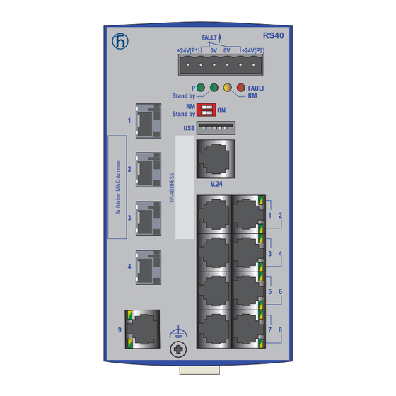
1.1.5 Number of ports and media for RS40-... RS40 FAULT +24V(P1) 0V 0V +24V(P2) FAULT Stand by Stand by V.24 RS40 FAULT +24V(P1) 0V 0V +24V(P2) FAULT Stand by Stand by V.24 RS40-0009CCCCED... RS40-0009CCCCSD... RS40-0009CCCCTD... Figure 10: Device variants with 9 * 1000 Mbit/s ports (RS40-0009...) 1 to 5 and 8 to 9 –... -
Page 26: Device Variants With Poe (Optional)
Device variants with PoE (optional) 1.2.1 Number of ports and media for devices with PoE RS22 FAULT +24V(P1) 0V 0V +24V(P2) FAULT Stand by Stand by V.24 RS22-1700MMM2...P... Figure 11: RS22 device variants with PoE (example: RS22-1700MMM2...P...) 1 to 5 and 7 to 9 – see fig. - Page 27 RS32 FAULT +24V(P1) 0V 0V +24V(P2) FAULT Stand by Stand by V.24 RS32-0802OOZZ...P... Figure 12: RS32 device variants with 4 uplink ports (example: RS32- 0802OOZZ...P...) 1 to 5 and 7 to 9 – see fig. 9 6 – ports in compliance with 10/100BASE-T(X) (RJ45 connections; the PoE-capable ports 7 to 10 are indicated accordingly) Device variants RS22-...
-
Page 28: Poe Power Units
1.2.2 PoE power units The following PoE power units are available for supplying the devices with PoE voltage: RPS90/48V LV: Low-voltage PoE power unit Input voltage range: 24 V DC to 48 V DC Power output at up to +60 °C: 90 W Power output at +60 °C to +70 °C: 60 W RPS90/48V HV: High-voltage PoE power unit Input voltage range:... -
Page 29: Assembly And Start-Up
To attach an SFP module, first remove the protective cap over the socket. Push the SFP module with the lock closed into the socket until it latches audibly in place. Note: Only use Hirschmann SFP modules (see page 55 „Scope of delivery“). -
Page 30: Insert Data In Label Area
2.1.3 Insert data in label area The information field for the IP address on the front of the device helps you to structure your network installation clearly. RS20 FAULT +24V(P1) 0V 0V +24V(P2) FAULT Stand by Stand by V.24 Figure 14: Label area for IP address of device 1 –... -
Page 31: Rs20/Rs30/Rs40: Supply Voltage And Signal Contact
Before starting operation of the device, check whether the default settings of the DIP switch correspond to your requirements. 2.1.5 RS20/RS30/RS40: supply voltage and signal contact The supply voltage and the signal contact are connected via a 6-pin terminal block with a snap lock. Caution! Note the safety instructions (see on page 4 „Notes on safety“) -
Page 32: Rs22/Rs32: Supply Voltage And Signal Contact
Signal contact for RS20/RS30/RS40 The signal contact (“FAULT”, for pin assignment of terminal block, see fig. 16) monitors the functioning of the device, thus enabling remote di- agnostics. You can specify the type of function monitoring in the Man- agement. You can also use the switch Web page to switch the signal contact manually and thus control external devices. - Page 33 Note: The RS22/RS32 devices fulfill the technical data and the certifications when using the RPS90/48V LV and RPS90/48V HV power units from Hirschmann. Only use these power units, to ensure that the specifica- tions are fulfilled. RPS90/48V LV: connecting the input voltage With the RPS90/48V LV low-voltage PoE power unit, you connect a DC supply voltage of 24 V DC to 48 V DC at the input connection.
- Page 34 Figure Assignment Voltage range Protective conductor High-voltage input voltage: 60 V DC to 250 V DC Minus terminal of the supply voltage Plus terminal of the supply voltage = external fuse for supply voltages > 125 V DC Table 9: Connecting the high-voltage supply voltage at PoE power unit RPS90/48V HV (DC voltage) First connect the protective conductor to the protective conductor ter- minal.
-
Page 35: Installing The Device On The Din Rail Hub, Grounding
FAULT +48V(P1) 0V 0V +48V(P2) Figure 17: Connecting the PoE supply voltage at the 6-pin terminal block of device RS22/RS32 RS22/RS32 signal contact The signal contact (“FAULT”, for pin assignment of terminal block, see fig. 17) monitors the functioning of the device, thus enabling remote di- agnostics. - Page 36 Note: The shielding ground of the connectable twisted pair lines is con- nected to the front panel as a conductor. RS20/RS30/RS40 RS22/RS32 Figure 18: Mounting on the DIN rails DIN rail mounting on ships (RS30-0802...) When you are mounting your RS30-0802... Open Rail device on a DIN rail on ships and in similar applications, the Open Rail Mounting Kit available as an accessory can be used to avoid excessive resonance.
- Page 37 Figure 19: Mounting the RS30-0802... on ships with the Open Rail Mounting Kit 1 - Open Rail Mounting Kit 942 007-001 2 - Open Rail Mounting Kit 942 007-101 Mounting on the wall (RS22/RS32) In addition to the option of mounting them on a DIN rail, you can also mount the RS22/RS32 devices on the wall using the wall mounting plate supplied (see on page 55...
-
Page 38: Dimension Drawings
Grounding With the RS20/RS30/RS40, the front panel of the device is grounded via the separate ground screw. With the RS22/RS32, the front panel and the metal housing of the device is grounded via the separate ground screw. 2.1.8 Dimension drawings Dimension drawings for RS20/RS30/RS40 13,73 105,3... - Page 39 105,3 13,73 Figure 22: Dimensions of device variants RS20.../RS30.../RS40... with 8 to max. 10 ports Figure 23: Dimensions of device variants RS20.../RS30.../RS40... with 16 to max. 26 ports RS20/RS22/RS30/RS32/RS40 Release 12 07/09...
- Page 40 Dimension drawings for RS22/RS32 11,56 Figure 24: Dimensions of device variants RS22.../RS32... with 8 to max. 10 ports 11,56 Figure 25: Dimensions of device variants RS22.../RS32... with 16 to max. 26 ports RS20/RS22/RS30/RS32/RS40 Release 12 07/09...
-
Page 41: Installing The Terminal Block, Start-Up Procedure
Dimension drawings for PoE power units 7,05 Figure 26: Dimensions of RPS90/48V LV and RPS90/48V HV PoE power units 2.1.9 Installing the terminal block, start-up procedure Mount the terminal block for the voltage supply and signal contact on the front of the device using the snap lock. Make sure that the snap lock snaps into place. - Page 42 State on delivery: autonegotiation activated. The socket housing is electrically connected to the front panel. Figure Function One line pair One line pair 4,5,7,8 Not used Table 11: Pin assignment of a TP/TX interface in MDI-X mode, RJ45 socket 10/100 Mbit/s twisted-pair connection PoE (RS22-.../RS32-...) These connections are RJ45 sockets.
- Page 43 10/100/1000 Mbit/s twisted pair connection These connections are RJ45 sockets. 10/100/1000 Mbit/s TP ports enable the connection of terminal devices or independent network segments according to the IEEE 802.3 10BASE-T/ 100BASE-TX/1000BASE-T standard. These ports support: Autonegotiation Autopolarity Autocrossing (if autonegotiation is activated) 1000 Mbit/s full duplex 100 Mbit/s half-duplex mode, 100 Mbit/s full duplex mode 10 Mbit/s half-duplex mode, 10 Mbit/s full duplex mode...
-
Page 44: Display Elements
1 Gbit/s F/O connection These ports are SFP slots. 1 Gbit/s F/O ports enable the connection of terminal devices or indepen- dent network segments according to the IEEE 802.3 1000BASE-SX/ 1000BASE-LX standard. These ports support: Autonegotiation Note: Make sure that the LH ports are only connected with LH ports, SX ports are only connected with SX ports, and LX ports only with LX ports. - Page 45 RM - Ring Manager (green/yellow LED) Not glowing RM function not active Flashing green Incorrect configuration of the HIPER-Ring (e.g. the ring is not connected to the ring port). Stand-by Glowing green Stand-by mode enabled Not glowing Stand-by mode not enabled If the manual adjustment is active on the “FAULT”...
-
Page 46: Making Basic Settings
Making basic settings The IP parameters must be entered when the device is installed for the first time. The device provides 6 options for configuring IP addresses: Entry via V.24 connection Entry using the HiDiscovery protocol Configuration via BOOTP Configuration via DHCP Configuration via DHCP Option 82 Auto Configuration Adapter Further information on the basic settings of the device can be found in the... - Page 47 V.24 interface (external management) The V.24 interface is an RJ11 socket. At the V.24 connection, a serial interface is provided for the local connec- tion of an external management station (VT100 terminal or PC with corre- sponding terminal emulation) or an AutoConfiguration Adapter ACA 11. This enables you to set up a connection to the Command Line Interface (CLI) and to the system monitor.
-
Page 48: Disassembly
Disassembly Removing the device from the DIN rail To take the device off the DIN rail, insert a screwdriver horizontally un- der the housing into the locking slide, pull it (without tipping the screw- driver) downwards and lift the device upwards. RS20/RS30/RS40 RS22/RS32 Removing the device from the wall mounting plate... -
Page 49: Technical Data
Technical data General technical data Dimensions RS20-0400... 47 mm x 131 mm x 111 mm W x H x D RS20-08..., RS20-09..., RS30-0802 74 mm x 131 mm x 111 mm RS20-16..., RS20-17..., RS30-1602 110 mm x 131 mm x 111 mm RS20-24..., RS20-25..., RS30-2402 110 mm x 131 mm x 111 mm RS40-0009CCCCS... - Page 50 PoE power unit Nominal voltage AC 110 - 230 V, 50 - 60 Hz RPS90/48V HV Voltage range AC 90 - 265 V, 47 - 63 Hz (incl. max. tol- erances) Power consumption at 110 V AC 1.00 A Power consumption at 230 V AC 0.50 A Nominal voltage DC 60 - 250 V...
- Page 51 Operating tempera- RS20/RS30/RS40 Standard: 0 °C to +60 °C ture Extended: -40 °C to +70 °C RS22-..., RS32-... Standard: 0 °C to +60 °C Extended: -40 °C to +60 °C RS40-...B... (ATEX) Temperature Code T4: Standard (S) 0 °C to +60 °C RS40-...B...
- Page 52 Stability IEC 870-2-2 table 3 normal installation ac- — cording to EN 61850-3 Shock IEC 60068-2-27 Test Ea test level according to IEC 61131-2 IEC 870-2-2 table 3 normal installation ac- — cording to EN 61850-3 a. Product code A: Certification = CE, UL Product code B: Certification = CE, UL, GL, railway (along track), sub station, ATEX Product code H: Certification = CE, UL, GL, railway (along track), sub station page 14 „Combination options for RS20/30“...
- Page 53 Product Wave Fiber System at- Expansion Fiber data code length tenuation M-SFP- -SX/LC... MM 850 nm 50/125 µm 0-7.5 dB 0-550 m 3.0 dB/km, 400 MHz*km -LX/LC... MM 1310 nm 50/125 µm 0-11 dB 0-550 m 1.0 dB/km, 800 MHz*km -SX/LC...
- Page 54 Device name Device model Maximum Power output power con- sumption RS20-0900-... RS22-0900-... 3xFX port 9.6 W 32.8 Btu (IT)/h RS20-1700-... RS22-1700-... 3xFX port 13.7 W 46.7 Btu (IT)/h RS20-2500-... RS22-2500-... 3xFX port 16.4 W 56.0 Btu (IT)/h 4 uplink ports: RS30-0802-...
- Page 55 Scope of delivery Device Scope of delivery RS20-..., RS30-..., RS40-..., Device RS22-... or RS32-... Terminal block for supply voltage and signal contact Installation user manual and CD-ROM Order numbers/product description See table on page 14 „Combination options for RS20/30“ and table on page 17 „Combination options for RS40“.
- Page 56 Underlying norms and standards Norm cUL 508:1998 Safety for Industrial Control Equipment EN 50121-4:2006 Railway applications - EMC - emitted interference and interference immunity for signal and telecommunication systems EN 55022:2006 IT equipment – radio interference characteristics EN 60079-15 Electrical equipment for explosive gas atmospheres – part 15: Construction, testing and marking of protection type "n"...
- Page 57 ATEX RL 94/9 EG pending pending pending pending Table 22: Certifications - for the current status, visit www.hirschmann.com a. A, H and B stand for certification categories which you can learn from the product name. In the product name, the 16th item designates the information on the certification category. See table 14 „Combination options of device variants...
-
Page 58: A Further Support
Further support Technical questions and training courses In the event of technical queries, please contact your local Hirschmann distributor or Hirschmann office. You can find the addresses of our distributors on the Internet: www.hirschmann-ac.com. Our support line is also at your disposal: Tel.
Need help?
Do you have a question about the RS20 Series and is the answer not in the manual?
Questions and answers