Table of Contents
Advertisement
Quick Links
Advertisement
Table of Contents

Related Manuals for Advantech eWorx SE500


Summary of Contents for Advantech eWorx SE500
- Page 1 SE500 Series Switches User Manual...
- Page 2 SE500 Series Switches Advantech B+B SmartWorx Americas 707 Dayton Road Ottawa, IL 61350 USA Phone (815) 433-5100 Fax (815) 433-5105 Advantech B+B SmartWorx European Headquarters Westlink Commercial Park Oranmore, Co. Galway, Ireland Phone +353 91-792444 Fax +353 91-792445 www.advantech-bb.com support@advantech-bb.com...
-
Page 3: Table Of Contents
SE500 Series Switches CONTENTS List of Figures ................................. 8 List of Tables ................................14 Declaration of Conformity ............................20 Product Warranty – Limited Lifetime .......................... 22 1 Product Overview ..............................24 1.1 Supported Models ............................. 24 1.2 Specifications ..............................24 1.3 Hardware Views .............................. - Page 4 SE500 Series Switches 2.4.2 Removing SFP Modules ..........................42 2.5 Connecting the Switch to Ethernet Ports ......................43 2.5.1 RJ45 Ethernet Cable Wiring ........................43 2.6 Connecting the Switch to Console Port ......................44 2.7 Power Supply Installation ..........................46 2.7.1 Overview ..............................
- Page 5 SE500 Series Switches 4.0 Managing the Switch ............................. 58 4.1. Log In ................................58 4.2 Recommended Practices ........................... 58 4.2.1 Changing Default Password ........................59 4.3 Monitoring ................................. 60 4.3.1 Device Information ............................. 60 4.3.2 Logging Message ............................62 4.3.3 Port Monitoring ............................
- Page 6 SE500 Series Switches 4.5.7 802.3az EEE ..............................98 4.5.8 Multicast ..............................100 4.5.9 Jumbo Frame ............................106 4.5.10 Spanning Tree ............................107 4.5.11 X-Ring Elite .............................. 115 4.5.12 X-Ring Pro ............................... 117 4.5.13 Loopback Detection ..........................120 4.6 MAC Address Table ............................123 4.6.1 Static MAC ..............................
- Page 7 4.11.2 Backup Manager ............................. 203 4.11.3 Upgrade Manager ........................... 204 4.11.4 Dual Image .............................. 206 4.11.5 Save Configuration ..........................207 4.11.6 User Account ............................207 4.11.7 Reset System............................208 4.11.8 Reboot Device ............................208 Troubleshooting ................................ 209 Advantech B+B SmartWorx Technical Support ......................209...
-
Page 8: List Of Figures
SE500 Series Switches LIST OF FIGURES Figure 1: Front View ..............................26 Figure 2: System LED Panel ............................28 Figure 3: System LED Panel ............................30 Figure 4: Rear View ..............................32 Figure 5: Top View ............................... 33 Figure 6: Top View ............................... 34 Figure 7: Installing the DIN-Rail Mounting Kit ...................... - Page 9 SE500 Series Switches Figure 24: Terminal Receptor: Relay Contact for PoE models ..................49 Figure 25: Terminal Receptor: Power Input Contacts for Non PoE models ..............49 Figure 26: Terminal Receptor: Power Input Contacts for PoE models ................ 50 Figure 27: Removing a Terminal Block ........................
- Page 10 SE500 Series Switches Figure 49: L2 Switching > 802.1Q VLAN > Port to VLAN ....................90 Figure 50: L2 Switching > Q-in-Q > Global Settings ..................... 92 Figure 51: L2 Switching > Q-in-Q > Port Settings ......................93 Figure 52: L2 Switching > GARP > GARP Settings ......................96 Figure 53: L2 Switching >...
- Page 11 SE500 Series Switches Figure 74: L2 Switching > X-Ring Pro > X-Ring Pro Groups > Couple Setting ............. 119 Figure 75: L2 Switching > Loopback Detection > Global Settings ................121 Figure 76: L2 Switching > Loopback Detection > Port Settings .................. 122 Figure 77: MAC Address Table >...
- Page 12 SE500 Series Switches Figure 99: QoS > General > IP Precedence Mapping ....................152 Figure 100: QoS > QoS Basic Mode > Global Settings ....................154 Figure 101: QoS > QoS Basic Mode > Global Settings ....................154 Figure 102: QoS > QoS Basic Mode > Port Settings ....................154 Figure 103: QoS >...
- Page 13 SE500 Series Switches Figure 124: Management > SMTP Client > Profile Settings > Profile Target Mail Settings ........183 Figure 125: Management > SMTP Client > Sending Message ................... 184 Figure 126: Management > RMON > Rmon Statistics ....................185 Figure 127: Management >...
-
Page 14: List Of Tables
SE500 Series Switches LIST OF TABLES Table 1: Wide Temperature Models ..........................24 Table 2: Specifications ..............................25 Table 3: Front View Table ............................27 Table 4: System LED Panel ............................29 Table 5: System LED Panel ............................31 Table 6: Rear View ............................... - Page 15 SE500 Series Switches Table 24: System > System Time ..........................76 Table 25: System > System Time ..........................77 Table 26: L2 Switching > Port Configuration ........................ 79 Table 27: L2 Switching > Port Mirror ........................... 80 Table 28: L2 Switching > Port Mirror ........................... 80 Table 29: L2 Switching >...
- Page 16 SE500 Series Switches Table 49: L2 Switching > Multicast > MLD Snooping > MLD Querier................. 105 Table 50: L2 Switching > Multicast > MLD Snooping > MLD Static Group ..............106 Table 51: L2 Switching > Jumbo Frame ........................107 Table 52: L2 Switching >...
- Page 17 SE500 Series Switches Table 74: Security > DoS Prevention > DoS Port Settings ..................134 Table 75: Security > Applications > TELNET ....................... 135 Table 76: Security > Applications > SSH ........................136 Table 77: Security > Applications > HTTP........................137 Table 78: Security >...
- Page 18 SE500 Series Switches Table 99: Management > SNMP > SNMP Community ....................166 Table 100: Management > SNMP > SNMP User Settings ..................168 Table 101: Management > SNMP > SNMP Trap ......................169 Table 102: Available POE Switches ..........................170 Table 103: Management >...
- Page 19 SE500 Series Switches Table 124: Diagnostics > DDM ........................... 200 Table 125: Diagnostics > DDM ........................... 201 Table 126: Tools > IXM .............................. 202 Table 127: Tools > Backup Manager .......................... 204 Table 128: Tools > Upgrade Manager ........................206 Table 129: Tools >...
-
Page 20: Declaration Of Conformity
We recommend the use of shielded cables. This kind of cable is available from Advantech. Please contact your local supplier for ordering information. This product has passed the CE test for environmental specifications. Test conditions for passing included the equipment being operated within an industrial enclosure. - Page 21 SE500 Series Switches If one of the following situations arises, get the equipment checked by service personnel: The power cord or plug is damaged. Liquid has penetrated into the equipment. The equipment has been exposed to moisture.
-
Page 22: Product Warranty - Limited Lifetime
SE500 Series Switches PRODUCT WARRANTY – LIMITED LIFETIME Effective for products of Advantech B+B SmartWorx shipped on or after May 1, 2013, Advantech B+B SmartWorx warrants that each such product shall be free from defects in material and workmanship for its lifetime. - Page 23 Eligible items returned within 30 days of purchase qualify for a full refund (less shipping charges). Advantech B+B SmartWorx has the option to accept returns of products 30 days after the date of purchase and such returns are subject to a restocking fee of up to 20%. Software is not returnable if opened.
-
Page 24: Product Overview
SE500 Series Switches 1 PRODUCT OVERVIEW 1.1 SUPPORTED MODELS SUPPORTED MODELS SEC510-2SFP-T SEG510-2SFP-T SECP510-2SFP-T SEGP510-2SFP-T Table 1: Wide Temperature Models 1.2 SPECIFICATIONS Specifications Description Interface I/O Port 8 x RJ45 + 2 x Combo (RJ45/Fiber) Power Connector 6-pin removable screw terminal (power & relay) -
Page 25: Table 2: Specifications
SE500 Series Switches Temperature Ambient Relative 10 ~ 95% (non-condensing) Humidity Switch Properties MAC Address 8K-entry Switching SEC510-2SFP-T: 5.6 Gbps Bandwidth SECP510-2SFP-T: 5.6 Gbps SEG510-2SFP-T: 20 Gbps SEGP510-2SFP-T: 20 Gbps Power Power 12.1 W@48Vdc (System) -
Page 26: Hardware Views
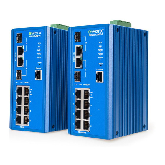
SE500 Series Switches 1.3 HARDWARE VIEWS 1.3.1 FRONT VIEW The following view applies to SEC510-2SFP-T and SEG510-2SFP-T. Figure 1: Front View... -
Page 27: Table 3: Front View Table
SE500 Series Switches Item Description ETH port Fiber ports x 2 ETH port RJ45 ports x 2 ETH port RJ45 ports x 8 LNK/ACT LED Link activity LED Speed LED Orange: 100M Green: 1G System LED panel See System LED Panel for further details. -
Page 28: Figure 2: System Led Panel
SE500 Series Switches System LED Panel Figure 2: System LED Panel... -
Page 29: Table 4: System Led Panel
SE500 Series Switches LED Name LED Color Description Solid green System is operating normally System is powered down / system crash / operation initiating R.M. Solid green Active when determining ring master PWR1 Solid green Powered up Powered down or not installed... -
Page 30: Figure 3: System Led Panel
SE500 Series Switches System LED Panel (only for SECP510-2SFP-T and SEGP510-2SFP-T) Figure 3: System LED Panel... -
Page 31: Table 5: System Led Panel
SE500 Series Switches LED Name LED Color Description Solid green System is operating normally System is powered down / system crash / operation initiating R.M. Solid green Active when determining ring master PWR1 Solid green Powered up Powered down or not installed... -
Page 32: Rear View
SE500 Series Switches 1.3.2 REAR VIEW The following view applies to SEC510-2SFP-T, SEG510-2SFP-T, SECP510-2SFP-T and SEGP510- 2SFP-T. Figure 4: Rear View... -
Page 33: Top View
SE500 Series Switches Item Description Wall mounting holes Screw holes (x6) used in the installation of a wall mounting plate DIN-Rail mounting Mounting plate used for the installation to a standard DIN rail plate Table 6: Rear View 1.3.3 TOP VIEW The following view applies to SEC510-2SFP-T and SEG510-2SFP-T. -
Page 34: Packing List
SE500 Series Switches The following view applies SECP510-2SFP-T and SEGP510-2SFP-T. Figure 6: Top View Item Description Ground terminal Screw terminal used to ground chassis Terminal block Connect cabling for power and alarm wiring Table 8: Top View 1.4 PACKING LIST The product package you have received should contain the following items. -
Page 35: Switch Installation
SE500 Series Switches 2. SWITCH INSTALLATION 2.1 INSTALLATION GUIDELINES The following guidelines are provided to optimize the device performance. Review the guidelines before installing the device. Make sure cabling is away from sources of electrical noise. Radios, power lines, and ... -
Page 36: Installing The Switch
SE500 Series Switches The switch is now ready for installation on its final location. 2.3 INSTALLING THE SWITCH 2.3.1 DIN RAIL MOUNTING The DIN rail mount option is the quickest installation option. Additionally, it optimizes the use of rail space. -
Page 37: Wall-Mounting
SE500 Series Switches Removing the DIN-Rail Mounting Kit Push the switch down to free the bottom of the plate from the DIN rail. Rotate the bottom of the device towards you and away from the DIN rail. Once the bottom is clear of the DIN rail, lift the device straight up to unhook it from the DIN rail. -
Page 38: Figure 9: Installing Wall Mount Plates
SE500 Series Switches Figure 9: Installing Wall Mount Plates Once the wall mounting plates are secure on the device, you will need to attach the wall screws (x6). Locate the installation site and place the switch against the wall, making sure it is the final installation location. -
Page 39: Figure 10: Securing Wall Mounting Screws
SE500 Series Switches Figure 10: Securing Wall Mounting Screws Make sure the screws dimensions are suitable for use with the wall mounting plate. Do not completely tighten the screws into the wall. A final adjustment may be needed before fully securing the wall mounting plates on the wall. -
Page 40: Installing And Removing Sfp Modules
The Gigabit Ethernet ports on the switch are 100/1000Base SFP Fiber ports, which require using the 100M or 1G mini-GBIC fiber transceivers to work properly. Advantech provides completed transceiver models for different distance requirement. The concept behind the LC port and cable is quite straight forward. Suppose that you are connecting devices I and II;... -
Page 41: Figure 13: Installing An Sfp Transceiver
SE500 Series Switches Position the SFP transceiver with the handle on top, see the following figure. Locate the triangular marking in the slot and align it with the bottom of the transceiver. Insert the SFP transceiver into the slot until it clicks into place. -
Page 42: Removing Sfp Modules
SE500 Series Switches Figure 14: Attaching a Fiber Optic Cable to a Transceiver Repeat the previous procedures to install any additional SFP transceivers in the switch. The fiber port is now set up. 2.4.2 REMOVING SFP MODULES To disconnect an LC connector, use the following guidelines: Press down and hold the locking clips on the upper side of the optic cable. -
Page 43: Connecting The Switch To Ethernet Ports
SE500 Series Switches Figure 16: Removing an SFP Transceiver Replace the dust plug on the slot if you are not installing a transceiver. The dust plug protects hardware from dust contamination. 2.5 CONNECTING THE SWITCH TO ETHERNET PORTS 2.5.1 RJ45 ETHERNET CABLE WIRING For RJ45 connectors, data-quality, twisted pair cabling (rated CAT5 or better) is recommended. -
Page 44: Connecting The Switch To Console Port
SE500 Series Switches Figure 17: Ethernet Plug & Connector Pin Position Maximum cable length: 100 meters (328 ft.) for 10/100/1000BaseT. 2.6 CONNECTING THE SWITCH TO CONSOLE PORT The industrial switch supports a secondary means of management. By connecting the RJ45 to RS232 serial cable between a COM port on your PC (9-pin D-sub female) and the switch’s RJ45... -
Page 45: Figure 20: Pin Assignment
SE500 Series Switches RJ45 Connector Connector 1. Orange/White 2. Orange 3. Green/White 4. Blue 5. Blue/White 6. Green 7. Brown/White 8. Brown Table 10: Pin Assignment Figure 20: Pin Assignment... -
Page 46: Power Supply Installation
SE500 Series Switches 2.7 POWER SUPPLY INSTALLATION 2.7.1 OVERVIEW Power down and disconnect the power cord before servicing or wiring the switch Do not disconnect modules or cabling unless the power is first switched off. The device only supports the voltage outlined in the type plate. Do not use any other power components except those specifically designated for the switch device. -
Page 47: Considerations
SE500 Series Switches 2.7.2 CONSIDERATIONS Take into consideration the following guidelines before wiring the device: The Terminal Block (CN1) is suitable for 12-24 AWG (3.31 - 0.205 mm ). Torque value 7 lb- The cross sectional area of the earthing conductors shall be at least 3.31 mm ... -
Page 48: Wiring A Relay Contact
SE500 Series Switches Electromagnetic Interference (EMI) affects the transmission performance of a device. By properly grounding the device to earth ground through a drain wire, you can setup the best possible noise immunity and emissions. Figure 22: Grounding Connection By connecting the ground terminal by drain wire to earth ground the switch and chassis can be ground. -
Page 49: Wiring The Power Inputs
SE500 Series Switches Figure 24: Terminal Receptor: Relay Contact for PoE models The terminal receptor includes a total of six pins: two for PWR1, two for PWR2 and two for a fault circuit. 2.7.5 WIRING THE POWER INPUTS Do not disconnect modules or cabling unless the power is first switched off. -
Page 50: Figure 26: Terminal Receptor: Power Input Contacts For Poe Models
SE500 Series Switches Figure 26: Terminal Receptor: Power Input Contacts for PoE models To wire the power inputs: Make sure the power is not connected to the switch or the power converter before proceeding. Loosen the screws securing terminal block to the terminal block receptor. -
Page 51: Reset Button
SE500 Series Switches Figure 28: Installing DC Wires in a Terminal Block Align the terminal block over the terminal block receptor on the switch. Insert the terminal block and press it in until it is flush with the terminal block receptor. -
Page 52: Configuration Utility
SE500 Series Switches 3. CONFIGURATION UTILITY 3. FIRST TIME SETUP 3.1.1 OVERVIEW The Industrial Ethernet Managed Switch is a configurable device that facilitates the interconnection of Ethernet devices on an Ethernet network. This includes computers, operator interfaces, I/O, controllers, RTUs, PLCs, other switches/hubs or any device that supports the standard IEEE 802.3 Ethernet protocol. -
Page 53: Administrative Interface Access
SE500 Series Switches 3.1.3 ADMINISTRATIVE INTERFACE ACCESS There are several administrative interfaces to the switch: This is the recommended method for managing the switch. A terminal interface via the RS232/USB port or over the network using telnet or Secure Shell (SSH). - Page 54 SE500 Series Switches DHCP Enabled/Disabled: The switch can automatically obtain an IP address from a server using the Dynamic Host Configuration Protocol (DHCP). This can speed up initial set up, as the network administrator does not have to find an open IP address.
-
Page 55: Configuring The Ethernet Ports
SE500 Series Switches 3.1.6 CONFIGURING THE ETHERNET PORTS The switch comes with default port settings that should allow you to connect to the Ethernet Ports without any necessary configuration. Should there be a need to change the name of the ports, negotiation settings or flow control settings, you can do this in the Port Configuration menu. -
Page 56: Command Line Interface Configuration
SE500 Series Switches 3.2 COMMAND LINE INTERFACE CONFIGURATION 3.2.1 INTRODUCTION TO COMMAND-LINE INTERFACE (CLI) The command-line interface (CLI) is constructed with an eye toward automation of CLI-based configuration. The interaction is modeled on that used in many Internet protocols such as Telnet, FTP, and SMTP. -
Page 57: Web Browser Configuration
SE500 Series Switches 3.3 WEB BROWSER CONFIGURATION The switch has an HTML based user interface embedded in the flash memory. The interface offers an easy to use means to manage basic and advanced switch functions. The interface allows for local or remote switch configuration anywhere on the network. -
Page 58: Managing The Switch
SE500 Series Switches 4.0 MANAGING THE SWITCH 4.1. LOG IN To access the login window, connect the device to the network, see “Connecting the Switch to Ethernet Ports” on page 19. Once the switch is installed and connected, power on the switch see the following procedures to log into your switch. -
Page 59: Changing Default Password
SE500 Series Switches 4.2.1 CHANGING DEFAULT PASSWORD In keeping with good management and security practices, it is recommended that you change the default password as soon as the device is functioning and setup correctly. The following details the necessary steps to change the default password. -
Page 60: Monitoring
SE500 Series Switches 4.3 MONITORING 4.3.1 DEVICE INFORMATION The Device Information menu lists information, such as: System Name, System Location, MAC Address, Firmware version, and more, pertaining to the system. The information is for review only. To modify the device information, see the respective item within the user interface. -
Page 61: Table 11: Monitoring > Device Information
SE500 Series Switches The following table describes the items in the previous figure. Item Description System Name Click Switch to enter the system name: up to 128 alphanumeric characters (default is Switch). System Location Click Default to enter the location: up to 256 alphanumeric characters (default is Default). -
Page 62: Logging Message
SE500 Series Switches 4.3.2 LOGGING MESSAGE The Logging Message Filter page allows you to enable the display of logging message filter. To access this page, click Monitoring > Logging Message. Figure 33: Monitoring > Logging Message... -
Page 63: Table 12: Monitoring > Logging Message
SE500 Series Switches The following table describes the items in the previous figure. Item Description Target Click the drop-down menu to select a target to store the log messages. Buffered: Store log messages in RAM. All log messages are cleared after system reboot. -
Page 64: Port Monitoring
SE500 Series Switches 4.3.3 PORT MONITORING Port Network Monitor is a bandwidth and network monitoring tool for the purpose of capturing network traffic and measuring of network throughput. The monitoring functionality includes listing of port statistics as well as port utilization. -
Page 65: Link Aggregation
SE500 Series Switches Figure 35: Monitoring > Port Monitoring > Port Utilization The following table describes the items in the previous figure. Item Description Refresh period Click the drop-down menu to select and designate a period (second intervals) to refresh the information (TX and RX) listings. -
Page 66: Figure 36: Monitoring > Lldp Statistics
SE500 Series Switches Figure 36: Monitoring > LLDP Statistics The following table describes the items in the previous figure. Item Description Clear Click Clear to reset LLDP Statistics of all the interfaces. Refresh Click Refresh to update the data on the screen with the present state of the data in the switch. -
Page 67: Igmp Statistics
SE500 Series Switches 4.3.6 IGMP STATISTICS The IGMP Statistics function displays statistical package information for IP multicasting. To access this page, click Monitoring > IGMP Statistics. Table 16: Monitoring > IGMP Statistics... -
Page 68: System
SE500 Series Switches The following table describes the items in the previous figure. Item Description Clear Click Clear to refresh IGMP Statistics of all the interfaces. Refresh Click Refresh to update the data on the screen with the present state of the data in the switch. -
Page 69: Dhcp Client Option 82
SE500 Series Switches Item Description Mode Click the radio button to select the IP Address Setting mode: Static or DHCP. IP Address Enter a value to specify the IP address of the interface. The default is 192.168.1.1. Subnet Mask Enter a value to specify the IP subnet mask for the interface. -
Page 70: Figure 38: System > Dhcp Client Option 82
SE500 Series Switches Figure 38: System > DHCP Client Option 82... -
Page 71: Dhcp Auto Provision
SE500 Series Switches The following table describes the items in the previous figure. Item Description Mode Click the radio button to enable or disable the DHCP Client Option 82 mode. Circuit ID Format Click the drop-down menu to set the ID format: String, Hex, User Definition. -
Page 72: Figure 39: System > Dhcp Auto Provision
SE500 Series Switches Figure 39: System > DHCP Auto Provision The following table describes the items in the previous figure. Item Description Status Select the radio button to enable or disable the DHCP Auto Provisioning Setting. Apply Click Apply to save the values and update the screen. -
Page 73: Ipv6 Settings
SE500 Series Switches 4.4.4 IPV6 SETTINGS To access this page, click System > IPv6 Settings. Table 21: System > IPv6 Settings... -
Page 74: Management Vlan
SE500 Series Switches The following table describes the items in the previous figure. Item Description Auto Configuration Select the radio button to enable or disable the IPv6. IPv6 Address Enter the IPv6 address for the system. Gateway Enter the gateway address for the system. -
Page 75: Table 23: System > Management Vlan
SE500 Series Switches The following table describes the items in the previous figure. Item Description Management VLAN Click the drop-down menu to select a defined VLAN. Apply Click Apply to save the values and update the screen. Table 23: System > Management VLAN... -
Page 76: System Time
SE500 Series Switches 4.4.6 SYSTEM TIME To access this page, click System > System Time. Table 24: System > System Time... -
Page 77: Table 25: System > System Time
SE500 Series Switches The following table describes the items in the previous figure. Item Description Enable SNTP Click the radio button to enable or disable the SNTP. SNTP/NTP Server Enter the address of the SNTP server. This is a text string of up to 64 characters Address containing the encoded unicast IP address or hostname of a SNTP server. -
Page 78: L2 Switching
SE500 Series Switches 4.5 L2 SWITCHING 4.5.1 PORT CONFIGURATION Port Configuration describes how to use the user interface to configure LAN ports on the switch. To access this page, click L2 Switching > Port Configuration. Figure 41: L2 Switching > Port Configuration... -
Page 79: Port Mirror
SE500 Series Switches The following table describes the items in the previous figure. Item Description Port Click the drop-down menu to select the port for the L2 Switch setting. Enabled Click the radio-button to enable or disable the Port Setting function. -
Page 80: Table 27: L2 Switching > Port Mirror
SE500 Series Switches Table 27: L2 Switching > Port Mirror The following table describes the items in the previous figure. Item Description Session ID Click the drop-down menu to select a port mirroring session from the list. The number of sessions allowed is platform specific. -
Page 81: Link Aggregation
SE500 Series Switches 4.5.3 LINK AGGREGATION Link Aggregation is a method for combining multiple network connections in parallel in order to increase throughput beyond the capability of a single connection, and to provide redundancy in case one of the links should fail. -
Page 82: Figure 43: L2 Switching > Link Aggregation > Lag Management
SE500 Series Switches LAG Management Link aggregation is also known as trunking. It is a feature available on the Ethernet gateway and is used with Layer 2 Bridging. Link aggregation allows for the logical merging of multiple ports into a single link. -
Page 83: Figure 44: L2 Switching > Link Aggregation > Lag Port Settings
SE500 Series Switches The following table describes the items in the previous figure. Item Description Click the drop-down menu to select the designated trunk group: Trunk 1 ~8. Name Enter an entry to specify the LAG name. Type Click the radio button to specify the type mode: Static or LACP. -
Page 84: Figure 45: L2 Switching > Link Aggregation > Lacp Priority Settings
SE500 Series Switches The following table describes the items in the previous figure. Item Description LAG Select Click the drop-down menu to select a predefined LAG trunk definition: LAG 1-8. Enabled Click the radio button to enable or disable the LAG Port. -
Page 85: Figure 46: L2 Switching > Link Aggregation > Lacp Port Settings
SE500 Series Switches The following table describes the items in the previous figure. Item Description System Priority Enter the value (1-65535) to designate the LACP system priority. Apply Click Apply to save the values and update the screen. Table 32: L2 Switching > Link Aggregation > LACP Priority Settings... -
Page 86: Q Vlan
SE500 Series Switches The following table describes the items in the previous figure. Item Description Port Select Select a port for the LACP Port Settings. The listed available settings are: FE1- FE8, GE1-GE2. However, the available settings are dependent on the connected LACP device and may not be listed as displayed in the current figure. -
Page 87: Figure 47: L2 Switching > 802.1Q Vlan > Vlan Management
SE500 Series Switches VLAN Management The management of VLANs is available through the VLAN Settings page. Through this page you can add or delete VLAN listings and add a prefix name to an added entry. To access this page, click L2 Switching > 802.1Q VLAN > VLAN Management. -
Page 88: Figure 48: L2 Switching > 802.1Q Vlan > Pvid Settings
SE500 Series Switches To access this page, click L2 Switching > 802.1Q VLAN > PVID Settings. Figure 48: L2 Switching > 802.1Q VLAN > PVID Settings... -
Page 89: Table 35: L2 Switching > 802.1Q Vlan > Pvid Settings
SE500 Series Switches The following table describes the items in the previous figure. Item Description Port Select Click the drop-down menu to select a port and edit its settings: FE1-FE8, GE1- GE2, or Trunk1 - Trunk8. PVID Enter the VLAN ID you want assigned to untagged or priority tagged frames received on this port. -
Page 90: Figure 49: L2 Switching > 802.1Q Vlan > Port To Vlan
SE500 Series Switches Figure 49: L2 Switching > 802.1Q VLAN > Port to VLAN... -
Page 91: Q-In-Q
SE500 Series Switches The following table describes the items in the previous figure. Item Description Port Displays the assigned port to the entry. Interface VLAN Mode Displays the assigned mode to the listed VLAN port. Hybrid: Port hybrid model. -
Page 92: Figure 50: L2 Switching > Q-In-Q > Global Settings
SE500 Series Switches via a double-tagged (trunk) port, where both inner and outer VLANs are handled by the attached machine (which sees double-tagged 802.1ad VLAN frames). Global Settings The Global Settings page allows you to set the outer VLAN Ethertype setting. -
Page 93: Figure 51: L2 Switching > Q-In-Q > Port Settings
SE500 Series Switches Item Description Outer VLAN Enter the outer VLAN handled by the switch giving the attached machine Ethertype a single-tagged 802.1Q VLAN frame. Apply Click Apply to save the values and update the screen. Table 38. L2 Switching > Q-in-Q > Global Settings Port Settings The Port Settings page allows you to define the outer PVID and outer mode for a selected port. -
Page 94: Table 39: L2 Switching > Q-In-Q > Port Settings
SE500 Series Switches The following table describes the items in the previous figure. Item Description Port Select Enter the switch port (part of VLAN configuration) to configure the selection as a tunnel port. Outer PVID Enter the Port VLAN ID (PVID) to assigned the native VLAN ID. All untagged traffic coming in or out of the 802.1Q port is forwarded based on the PVID value... -
Page 95: Garp
SE500 Series Switches Item Description Port Select Enter the switch port (part of VLAN configuration) to configure the selection as a tunnel port. Outer PVID Enter the Port VLAN ID (PVID) to assigned the native VLAN ID. All untagged traffic coming in or out of the 802.1Q port is forwarded based on... -
Page 96: Figure 52: L2 Switching > Garp > Garp Settings
SE500 Series Switches Figure 52: L2 Switching > GARP > GARP Settings... -
Page 97: Table 41: L2 Switching > Garp > Garp Settings
SE500 Series Switches The following table describes the items in the previous figure. Item Description Join Time Enter a value to specify the time between the transmission of GARP PDUs registering (or re-registering) membership for a VLAN or multicast group in centiseconds. -
Page 98: Az Eee
SE500 Series Switches Figure 53: L2 Switching > GARP > GVRP Settings The following table describes the items in the previous figure. Item Description Status Click to enable or disable the GARP VLAN Registration Protocol administrative mode for the switch. The factory default is Disable. -
Page 99: Figure 54: L2 Switching > 802.3Az Eee
SE500 Series Switches Figure 54: L2 Switching > 802.3az EEE The following table describes the items in the previous figure. Item Description Port Select Enter the port to setup the EEE function. State Click Enabled or Disabled to set the state mode of the port select setting. -
Page 100: Multicast
SE500 Series Switches 4.5.8 MULTICAST Multicast forwarding allows a single packet to be forwarded to multiple destinations. The service is based on L2 switch receiving a single packet addressed to a specific Multicast address. Multicast forwarding creates copies of the packet, and transmits the packets to the relevant ports. -
Page 101: Figure 56: L2 Switching > Multicast > Igmp Snooping > Igmp Settings
SE500 Series Switches multicast streams. Multicasts can be filtered from the links which do not need them in turn controlling which ports receive specific multicast traffic. IGMP Settings To access this page, click L2 Switching > Multicast > IGMP Snooping > IGMP Settings. -
Page 102: Figure 57: L2 Switching > Multicast > Igmp Snooping > Igmp Querier
SE500 Series Switches To access this page, click L2 Switching > Multicast > IGMP Snooping > IGMP Querier. Figure 57: L2 Switching > Multicast > IGMP Snooping > IGMP Querier The following table describes the items in the previous figure. -
Page 103: Figure 58: L2 Switching > Multicast > Igmp Snooping > Igmp Static Groups
SE500 Series Switches Figure 58: L2 Switching > Multicast > IGMP Snooping > IGMP Static Groups The following table describes the items in the previous figure. Item Description VLAN ID Select the VLAN ID to define IGMP static group. -
Page 104: Figure 59: L2 Switching > Multicast > Mld Snooping > Mld Settings
SE500 Series Switches MLD Settings To access this page, click L2 Switching > Multicast > MLD Snooping > MLD Settings. Figure 59: L2 Switching > Multicast > MLD Snooping > MLD Settings The following table describes the items in the previous figure. -
Page 105: Figure 60: L2 Switching > Multicast > Mld Snooping > Mld Querier
SE500 Series Switches Figure 60: L2 Switching > Multicast > MLD Snooping > MLD Querier The following table describes the items in the previous figure. Item Description VLAN ID Enter the VLAN ID to configure. Querier State Select Enable or Disable status on the selected VLAN. -
Page 106: Jumbo Frame
SE500 Series Switches Figure 61: L2 Switching > Multicast > MLD Snooping > MLD Static Group The following table describes the items in the previous figure. Item Description VLAN ID Enter the VLAN ID to define the local MLD Static Group. -
Page 107: Spanning Tree
SE500 Series Switches Figure 62: L2 Switching > Jumbo Frame The following table describes the items in the previous figure. Item Description Jumbo Frame (Bytes) Enter the variable in bytes (1518 to 9216) to define the jumbo frame size. -
Page 108: Figure 63: L2 Switching > Spanning Tree > Stp Global Settings
SE500 Series Switches Figure 63: L2 Switching > Spanning Tree > STP Global Settings The following table describes the items in the previous figure. Item Description Enabled Click the radio-button to enable or disable the STP status. BPDU Forward Select flooding or filtering to designate the type of BPDU packet. -
Page 109: Figure 64: L2 Switching > Spanning Tree > Stp Port Settings
SE500 Series Switches STP Port Settings The STP Port Settings page allows you to configure the ports for the setting, port’s contribution, configure edge port, and set the status of the BPDU filter. To access this page, click L2 Switching > Spanning Tree > STP Port Settings. -
Page 110: Table 53: L2 Switching > Spanning Tree > Stp Port Settings
SE500 Series Switches The following table describes the items in the previous figure. Item Description Port Select Select the port list to specify the ports that apply to this setting. Admin Enable Select Enabled or Disabled to setup the admin profile for the STP port. -
Page 111: Figure 65: L2 Switching > Spanning Tree > Stp Bridge Settings
SE500 Series Switches Figure 65: L2 Switching > Spanning Tree > STP Bridge Settings The following table describes the items in the previous figure. Item Description Priority Click the drop-down menu to select the STP bridge priority. Forward Delay Enter the variable (4 to 30) to set the forward delay for STP bridge settings. -
Page 112: Figure 66: L2 Switching > Spanning Tree > Stp Port Advanced Settings
SE500 Series Switches STP Port Advanced Settings The STP Port Advanced Settings page allows you to select the port list to apply this setting. To access this page, click L2 Switching > Spanning Tree > STP Port Advanced Settings. -
Page 113: Figure 67: L2 Switching > Spanning Tree > Mst Config Identification
SE500 Series Switches Figure 67: L2 Switching > Spanning Tree > MST Config Identification The following table describes the items in the previous figure. Item Description Configuration Name Enter the identifier used to identify the configuration currently being used. It may be up to 32 characters. -
Page 114: Figure 68: L2 Switching > Spanning Tree > Mst Instance Id Settings
SE500 Series Switches Figure 68: L2 Switching > Spanning Tree > MST Instance ID Settings The following table describes the items in the previous figure. Item Description MSTI ID Enter the MST instance ID (0-15). VID List Enter the pre-configured VID list. -
Page 115: X-Ring Elite
SE500 Series Switches Figure 69: L2 Switching > Spanning Tree > MST Instance Priority Settings The following table describes the items in the previous figure. Item Description MSTI ID Click the drop-down menu to specify the MST instance. Priority... -
Page 116: Figure 70: L2 Switching > X-Ring Elite > X-Ring Elite Settings
SE500 Series Switches X-Ring Elite Settings The X-Ring Elite Settings allows you to enable or disable the state of the X-Ring settings. To access this page, click L2 Switching > X-Ring Elite > X-Ring Elite Settings. Figure 70: L2 Switching > X-Ring Elite > X-Ring Elite Settings The following table describes the items in the previous figure. -
Page 117: X-Ring Pro
SE500 Series Switches The following table describes the items in the previous figure. Item Description Ring ID Enter a number to specifies a ranging from 1 to 255 to identify a given X-Ring Elite group. Role Click the drop-down menu to select the ring role. -
Page 118: Figure 73: L2 Switching > X-Ring Pro > X-Ring Pro Groups > X-Ring Pro Groups Settings
SE500 Series Switches The following table describes the items in the previous figure. Item Description State Select Enabled or Disabled to setup the X-Ring Pro mode. Apply Click Apply to save the values and update the screen. Table 61: L2 Switching > X-Ring Pro > X-Ring Pro Settings... -
Page 119: Figure 74: L2 Switching > X-Ring Pro > X-Ring Pro Groups > Couple Setting
SE500 Series Switches The following table describes the items in the previous figure. Item Description Ring ID Enter a number to specifies a ranging from 1 to 255 to identify a given X-Ring Pro group. Port 1 Click the drop-down menu to define the port designation. -
Page 120: Loopback Detection
SE500 Series Switches The following table describes the items in the previous figure. Item Description Couple Ring ID Enter a number to specifies a ranging from 1 to 255 to identify a given X-Ring group. Port Enter the port to assign to define the couple setting. -
Page 121: Figure 75: L2 Switching > Loopback Detection > Global Settings
SE500 Series Switches Figure 75: L2 Switching > Loopback Detection > Global Settings The following table describes the items in the previous figure. Item Description State Select Enabled or Disabled to setup the loopback mode. Interval Enter the variable in seconds (1 to 32767) to set the interval at which frames are transmitted. -
Page 122: Figure 76: L2 Switching > Loopback Detection > Port Settings
SE500 Series Switches Figure 76: L2 Switching > Loopback Detection > Port Settings The following table describes the items in the previous figure. Item Description Port Select Enter the port to define the local loopback detection setting. Enabled Select Enabled or Disabled to setup the Loopback Detection function. -
Page 123: Mac Address Table
SE500 Series Switches 4.6 MAC ADDRESS TABLE The MAC Address Table provides access to the Static MAC Settings, MAC Aging Time, and Dynamic Forwarding. 4.6.1 STATIC MAC The Static MAC page allows you to configure the address for forwarding of packets, the VLAN ID of the listed MAC address and the designated Port. -
Page 124: Mac Aging Time
SE500 Series Switches The following table describes the items in the previous figure. Item Description MAC Address Enter the MAC address to which packets are statically forwarded. VLAN Click the drop-down menu to select the VLAN ID number of the VLAN for which the MAC address is residing. -
Page 125: Dynamic Forwarding Table
SE500 Series Switches The following table describes the items in the previous figure. Item Description Aging Time Enter the variable (10 to 630) to define the time required for aging. Apply Click Apply to save the values and update the screen. -
Page 126: Security
SE500 Series Switches The following table describes the items in the previous figure. Item Description Port Click the drop-down menu to select the port number to show or clear dynamic MAC entries. If a port, VLAN or MAC address is not selected the whole dynamic MAC table is displayed or cleared. -
Page 127: Figure 80: Security > Storm Control > Global Settings
SE500 Series Switches Figure 80: Security > Storm Control > Global Settings The following table describes the items in the previous figure. Item Description Unit Select pps or bps control units for the Storm Control function. Preamble & IFG Select Excluded or Included to setup the Storm Control Global settings. -
Page 128: Figure 81: Security > Storm Control > Port Settings
SE500 Series Switches Figure 81: Security > Storm Control > Port Settings... -
Page 129: Table 70: Security > Storm Control > Port Settings
SE500 Series Switches The following table describes the items in the previous figure. Item Description Port Enter the port number to designate the local port for the Storm Control function. Port State Select Disabled or Enabled to define the port state... -
Page 130: Port Security
SE500 Series Switches 4.7.2 PORT SECURITY The Port Security page allows you to configure port isolation behavior. To access this page, click Security > Port Security Figure 82: Security > Port Security The following table describes the items in the previous figure. -
Page 131: Protected Ports
SE500 Series Switches 4.7.3 PROTECTED PORTS The Protected Port page allows you to configure a single or multiple ports as a protected or unprotected type. To access this page, click Security > Protected Ports. Figure 83: Security > Protected Ports The following table describes the items in the previous figure. -
Page 132: Figure 84: Security > Dos Prevention > Dos Global Settings
SE500 Series Switches To access this page, click Security > DoS Prevention > DoS Global Settings. Figure 84: Security > DoS Prevention > DoS Global Settings... -
Page 133: Table 73: Security > Dos Prevention > Dos Global Settings
SE500 Series Switches Item Description DMAC = SMAC Click Enabled or Disabled to define DMAC-SMAC for the DoS Global settings. LAND Click Enabled or Disabled to define LAND for the DoS Global settings. UDP Blat Click Enabled or Disabled to define UDP Blat for the DoS Global settings. -
Page 134: Figure 85: Security > Dos Prevention > Dos Port Settings
SE500 Series Switches DoS Port Settings The DoS Port Settings page allow you to configure DoS security (enabled or disabled) for the selected port. To access this page, click Security > DoS Prevention > DoS Port Settings. Figure 85: Security > DoS Prevention > DoS Port Settings The following table describes the items in the previous figure. -
Page 135: Applications
SE500 Series Switches 4.7.5 APPLICATIONS The Applications function allows you to configure various types of AAA lists. TELNET The TELNET page allows you to combine all kinds of AAA lists with the Telnet line. To access this page, click Security > Applications > TELNET. -
Page 136: Figure 87: Security > Applications > Ssh
SE500 Series Switches To access this page, click Security > Applications > SSH. Figure 87: Security > Applications > SSH The following table describes the items in the previous figure. Item Description SSH Service Click Enabled or Disabled to set up Ethernet encapsulation (remote access) through the Secure Shell (SSH) function. -
Page 137: Figure 89: Security > Applications > Https
SE500 Series Switches The following table describes the items in the previous figure. Item Description HTTP Service Click Enabled or Disabled to set up Ethernet encapsulation (remote access) through HTTP function. Session Timeout Enter the variable in minutes (0 to 86400) to define the timeout period for the HTTP session. -
Page 138: 138
SE500 Series Switches The following table describes the items in the previous figure. Item Description HTTPS Service Click Enabled or Disabled to set up Ethernet encapsulation over HTTPS. Session Timeout Enter the variable in minutes (0 to 86400) to define the timeout period for the HTTP session. -
Page 139: Figure 90: Security > 802.1X > 802.1X Settings
SE500 Series Switches Figure 90: Security > 802.1x > 802.1x Settings... -
Page 140: Table 79: Security > 802.1X > 802.1X Settings
SE500 Series Switches The following table describes the items in the previous figure. Item Description State Click Enabled or Disabled to set up 802.1x Setting function. Server IP Enter the IP address of the local server providing authentication function. -
Page 141: Ip Security
SE500 Series Switches Figure 91: Security > 802.1x > 802.1x Port Configuration The following table describes the items in the previous figure. Item Description Authentication based Click Port or Mac to designate the type of configuration for the 802.1x Port setting. -
Page 142: Figure 92: Security > Ip Security > Global Settings
SE500 Series Switches Figure 92: Security > IP Security > Global Settings The following table describes the items in the previous figure. Item Description Status Click Enabled or Disabled to define the global setting for the IP security function. -
Page 143: Qos
SE500 Series Switches The following table describes the items in the previous figure. Item Description IP Address Enter the source IP address to apply the IP Security function. IP Mask Enter the IP address for use in masking the previous IP Address. -
Page 144: Figure 94: Qos > General > Qos Properties
SE500 Series Switches Figure 94: QoS > General > QoS Properties The following table describes the items in the previous figure. Item Description QoS Mode Select Disabled or Basic to setup the QoS function. Apply Click Apply to save the values and update the screen. -
Page 145: Figure 95: Qos > General > Qos Settings
SE500 Series Switches Figure 95: QoS > General > QoS Settings The following table describes the items in the previous figure. Item Description Port Enter the port number to associate with the QoS setting. CoS Value Click the drop-down menu to designate the Class of Service (CoS) value (0 to 7) for the Port entry. -
Page 146: Figure 96: Qos > General > Qos Scheduling
SE500 Series Switches Queue Scheduling The switch support eight CoS queues for each egress port. For each of the eight queues, two types of scheduling can be configured: Strict Priority and Weighted Round Robin (WRR). Strict Priority scheduling is based on the priority of queues. Packets in a high-priority queue are always sent first and packets in a low-priority queue are only sent after all the high priority queues are empty. -
Page 147: Table 85: Qos > General > Qos Scheduling
SE500 Series Switches The following table describes the items in the previous figure. Item Description Queue Queue entry for egress port. Strict Select Strict to assign the scheduling designation to the selected queue. Select WRR to assign the scheduling designation to the selected queue. -
Page 148: Figure 97: Qos > General > Cos Mapping
SE500 Series Switches CoS Mapping The CoS Mapping allows you to apply CoS mapping. To access this page, click QoS > General > CoS Mapping. Figure 97: QoS > General > CoS Mapping... -
Page 149: Table 86: Qos > General > Cos Mapping
SE500 Series Switches The following table describes the items in the previous figure. Item Description CoS to Queue Mapping Class of Service Displays the CoS for the queue entry. Queue Click the drop-down menu to select the queue priority for selected CoS... -
Page 150: Figure 98: Qos > General > Dscp Mapping
SE500 Series Switches Figure 98: QoS > General > DSCP Mapping... -
Page 151: Table 87: Qos > General > Dscp Mapping
SE500 Series Switches The following table describes the items in the previous figure. Item Description DSCP to Queue Mapping DSCP Enter the DSCP entry to define the precedence values. Queue Click the drop-down menu to select the queue designation for the DSCP value. -
Page 152: Figure 99: Qos > General > Ip Precedence Mapping
SE500 Series Switches Figure 99: QoS > General > IP Precedence Mapping... -
Page 153: Qos Basic Mode
SE500 Series Switches The following table describes the items in the previous figure. Item Description IP Precedence to Queue Mapping IP Precedence Displays the IP precedence value for the queue map. Queue Click the drop-down menu to map a queue value to the selected IP precedence. -
Page 154: Figure 100: Qos > Qos Basic Mode > Global Settings
SE500 Series Switches The function is only available when QoS Properties is set to Basic. Figure 100: QoS > QoS Basic Mode > Global Settings The following table describes the items in the previous figure. Item Description Trust Mode Click the drop-down menu to select the trust state of the QoS basic mode. -
Page 155: Rate Limit
SE500 Series Switches The following table describes the items in the previous figure. Item Description Port Enter the port number for the QoS basic mode setting. Trust State Select Enabled or Disabled to set the port’s trust state status. -
Page 156: Figure 104: Qos > Rate Limit > Egress Bandwidth Control
SE500 Series Switches The following table describes the items in the previous figure. Item Description Port Enter the port number for the rate limit setup. State Select Disabled or Enabled to set the port’s state status. Rate (Kbps) Enter the value in Kbps (16 to 1000000) to set as the bandwidth rate for the selected port. -
Page 157: Figure 105: Qos > Rate Limit > Egress Queue
SE500 Series Switches The following table describes the items in the previous figure. Item Description Port Enter the port number to set the Egress Bandwidth Control. State Select Disabled or Enabled to set the Egress Bandwidth Control state. Rate (Kbps) Enter the value in Kbps (16 to 1000000) to set the Egress Bandwidth rate. -
Page 158: Management
SE500 Series Switches The following table describes the items in the previous figure. Item Description Port Click the drop-down menu to select the port to define the Egress queue. Queue Click the drop-down menu to set the queue order for the Egress setting. -
Page 159: Figure 106: Management > Lldp > Lldp System Settings
SE500 Series Switches Figure 106: Management > LLDP > LLDP System Settings... -
Page 160: Table 93: Management > Lldp > Lldp System Settings
SE500 Series Switches The following table describes the items in the previous figure. Item Description Enabled Click Enabled or Disabled to set the Global Settings state. LLDP PDU Disable Click to select the LLDP PDU handling action when LLDP is globally disabled. -
Page 161: Figure 107: Management > Lldp > Lldp Port Settings > Lldp Port Configuration
SE500 Series Switches Figure 107: Management > LLDP > LLDP Port Settings > LLDP Port Configuration The following table describes the items in the previous figure. Item Description Port Select Enter the port number associated with the LLDP setting. -
Page 162: Figure 109: Management > Lldp > Lldp Port Settings > Vlan Name Tlv Vlan Selection
SE500 Series Switches The following table describes the items in the previous figure. Item Description Port Select Enter the port number associated with the TLV (optional) selection. Optional TLV Select Click the drop-down menu to select the LLDP optional TLVs to be carried (multiple selections are allowed). -
Page 163: Figure 110: Management > Lldp > Lldp Remote Device Info
SE500 Series Switches The following table describes the items in the previous figure. Item Description Port Select Enter the port number to associated with the TLV selection. VLAN Select Select the VLAN Name ID to be carried out (multiple selection is allowed). -
Page 164: Snmp
SE500 Series Switches Item Description Detail Click to display the device details. Delete Click to delete the selected devices. Refresh Click to refresh the remote device information list. Table 97: Management > LLDP > LLDP Remote Device Info LLDP Overloading To access this page, click Management >... -
Page 165: Figure 112: Management > Snmp > Snmp Community
SE500 Series Switches The following table describes the items in the previous figure. Item Description State Click Enabled or Disabled to define the SNMP daemon. Apply Click Apply to save the values and update the screen. Table 98: Management > SNMP > SNMP Settings SNMP Community The SNMP Community page provides configuration options for the community. -
Page 166: Table 99: Management > Snmp > Snmp Community
SE500 Series Switches The following table describes the items in the previous figure. Item Description Community Name Enter a community name (up to 20 characters). Access Right Click the radio box to specify the access level (read only or read write) Apply Click Apply to save the values and update the screen. -
Page 167: Figure 113: Management > Snmp > Snmp User Settings
SE500 Series Switches SNMP User Settings The SNMP User Settings page allows you to create SNMP groups. The users have the same level of security and access control permissions as defined by the group settings. To access this page, click Management > SNMP > SNMP User Settings. -
Page 168: Table 100: Management > Snmp > Snmp User Settings
SE500 Series Switches The following table describes the items in the previous figure. Item Description User Name Enter a user name (up to 32 characters) to create an SNMP profile. Access Right Click read-only or read-write to define the access right for the profile. -
Page 169: Power Over Ethernet
SE500 Series Switches Figure 114: Management > SNMP > SNMP Trap The following table describes the items in the previous figure Item Description IP Address Enter the IP address to designate the SNMP trap host. Community Name Click the drop-down menu to select a defined community name. -
Page 170: Figure 115: Management > Power Over Ethernet > Poe System Settings
SE500 Series Switches Series Supported Models SE500 SECP510-2SFP-T, SEGP510-2SFP-T Table 102: Available POE Switches PoE System Settings The PoE System Settings page allows you to configure the overload disconnect and the maximum available wattage. To access this page, click Management > Power Over Ethernet > PoE System Settings. -
Page 171: Table 103: Management > Power Over Ethernet > Poe System Settings
SE500 Series Switches The following table describes the items in the previous figure. Item Description Maximum Power Select the value in Watts to set the maximum available power. Available OverLoad Disconnect Click the drop-down menu to designate the overload mode:... -
Page 172: Figure 116: Management > Power Over Ethernet > Poe Port Settings
SE500 Series Switches Figure 116: Management > Power Over Ethernet > PoE Port Settings... -
Page 173: Table 104: Management > Power Over Ethernet > Poe Port Settings
SE500 Series Switches The following table describes the items in the previous figure Item Description Port Click the drop-down menu to select a PoE port. Enabled Select Enabled or Disabled to designate the PoE port function by ports. Power Limit From Select Enabled or Disabled to designate the power limit classification. -
Page 174: Tcp Modbus
SE500 Series Switches 4.9.4 TCP MODBUS The TCP Modbus function allows for client-server communication between a switch module (server) and a device in the networking running MODBUS client software (client). TCP Modbus Settings The TCP Modbus Settings page allows you to configure the Modbus function. -
Page 175: Dhcp Server
SE500 Series Switches 4.9.5 DHCP SERVER The Dynamic Host Configuration Protocol (DHCP) is a network protocol enabling a server to automatically assign an IP address to a computer from a defined range of numbers configured for a given network. -
Page 176: Figure 119: Management > Dhcp Server > Global Settings
SE500 Series Switches Global Settings The Global Settings page allows you to configure the global settings for the DHCP function. To access this page, click Management > DHCP Server > Global Settings. Figure 119: Management > DHCP Server > Global Settings... -
Page 177: Table 107: Management > Dhcp Server > Global Settings
SE500 Series Switches The following table describes the items in the previous figure. Item Description Lease Time Type in the value designating the lease time (60 - 864000) in seconds for each setting lease. Low IP Address Type in the value designating the lowest range in the IP address pool. -
Page 178: Figure 120: Management > Dhcp Server > Port Settings
SE500 Series Switches Figure 120: Management > DHCP Server > Port Settings The following table describes the items in the previous figure. Item Description Port Select Click the drop-down menu to select a pre-defined port to configure. The suboptions are designated for the selected port. -
Page 179: Figure 121: Management > Dhcp Server > Option 82 Settings
SE500 Series Switches Option 82 Settings The Option 82 Settings, also known as the DHCP relay agent information option, provide information about the network location of a DHCP client. In turn, the DHCP server uses the information to implement IP addresses or other parameters for the client. -
Page 180: Table 109: Management > Dhcp Server > Option 82 Settings
SE500 Series Switches The following table describes the items in the previous figure. Item Description Entry Click the drop-down menu to select an entry for the Option 82 setting. Circuit ID Format Click the drop-down menu to select the format of the circuit ID: string or hex. -
Page 181: Smtp Client
SE500 Series Switches 4.9.6 SMTP CLIENT Simple Mail Transfer Protocol (SMTP) is a protocol to send e-mail messages between servers. SMTP is used to send messages from a mail client to a mail server. SMTP by default uses TCP port 25. -
Page 182: Figure 123: Management > Smtp Client > Profile Settings > Profile Settings
SE500 Series Switches Figure 123: Management > SMTP Client > Profile Settings > Profile Settings The following table describes the items in the previous figure. Item Description Profile ID Click the drop-down menu to select the identification type for the profile (1 or 2). -
Page 183: Figure 124: Management > Smtp Client > Profile Settings > Profile Target Mail Settings
SE500 Series Switches Figure 124: Management > SMTP Client > Profile Settings > Profile Target Mail Settings The following table describes the items in the previous figure. Item Description Profile ID Click the drop-down menu to select the identification type for the profile (1 or Target Mail Enter the email address of the target client. -
Page 184: Figure 125: Management > Smtp Client > Sending Message
SE500 Series Switches Figure 125: Management > SMTP Client > Sending Message The following table describes the items in the previous figure. Item Description Title Assign the title of the email. The maximum length is 20 characters (alphanumeric, symbols (. (dot), _ (underline), - (dash line) and space). -
Page 185: Rmon
SE500 Series Switches 4.9.7 RMON Remote monitoring (RMON) uses a client-server model to monitor/manage remote devices on a network. RMON Statistics The RMON Statistics page allows you to view information regarding packet sizes and information for physical layer errors. The information displayed is according to the RMON standard. -
Page 186: Figure 127: Management > Rmon > Rmon History
SE500 Series Switches The following table describes the items in the previous figure. Item Description Index Enter an entry selection (1 to 65535) to display its statistical information. Port Enter the respective port number for the selected entry. Owner Enter the name of the owner of the RMON group. -
Page 187: Table 115: Management > Rmon > Rmon History
SE500 Series Switches The following table describes the items in the previous figure. Item Description Index Enter the index entry (1 to 65535) to select the number of new history table entries. Port Select the specific port switch. Buckets Requested Enter the specific (1-50) number of samples to store. -
Page 188: Figure 128: Management > Rmon > Rmon Alarm
SE500 Series Switches Figure 128: Management > RMON > Rmon Alarm... -
Page 189: Table 116: Management > Rmon > Rmon Alarm
SE500 Series Switches The following table describes the items in the previous figure. Item Description Index Enter the index entry (1 to 65535) to define a specific Alarm Collection history entry. Interval Enter a value (1 to 2147483647) to define the interval value for the Alarm Collection history. -
Page 190: Figure 129: Management > Rmon > Rmon Event
SE500 Series Switches Figure 129: Management > RMON > RMON Event The following table describes the items in the previous figure. Item Description Index Enter the index entry (1 to 65535) to define a specific RMON event. Description Enter a value (1 to 2147483647) to define the interval value for the Alarm Collection history. -
Page 191: Diagnostics
SE500 Series Switches 4.10 DIAGNOSTICS Through the Diagnostics function configuration of settings for the switch diagnostics is available. 4.10.1 CABLE DIAGNOSTICS The Cable Diagnostics page allows you to select the port for applying a copper test. To access this page, click Diagnostics > Cable Diagnostics. -
Page 192: Figure 131: Diagnostics > Ping Test
SE500 Series Switches Figure 131: Diagnostics > Ping Test... -
Page 193: Table 119: Diagnostics > Ping Test
SE500 Series Switches The following table describes the items in the previous figure Item Description IP Address Enter the IP address or host name of the station to ping. The initial value is blank. The IP Address or host name you enter is not retained across a power cycle. -
Page 194: Ipv6 Ping Test
SE500 Series Switches 4.10.3 IPV6 PING TEST The IPv6 Ping Test page allows you to configure the Ping Test for IPv6. To access this page, click Diagnostics > IPv6 Ping Test. Figure 132: Diagnostics > IPv6 Ping Test... -
Page 195: Table 120: Diagnostics > Ipv6 Ping Test
SE500 Series Switches The following table describes the items in the previous figure. Item Description IPv6 Address Enter the IP address or host name of the station you want the switch to ping. The initial value is blank. The IP Address or host name you enter is not retained across a power cycle. -
Page 196: System Log
SE500 Series Switches 4.10.4 SYSTEM LOG Logging Service The Logging Service page allows you to setup the logging services feature for the system log. To access this page, click Diagnostics > System Log > Logging Service. Figure 133: Diagnostics > System Log > Logging Service The following table describes the items in the previous figure. -
Page 197: Figure 134: Diagnostics > System Log > Local Logging
SE500 Series Switches Figure 134: Diagnostics > System Log > Local Logging The following table describes the items in the previous figure. Item Description Target Enter the local logging target. Severity Click the drop-down menu to select the severity level for local log messages. -
Page 198: Figure 135: Diagnostics > System Log > System Log Server
SE500 Series Switches System Log Server The System Log Server page allows you to configure the log server. To access this page, click Diagnostics > System Log > System Log Server. Figure 135: Diagnostics > System Log > System Log Server... -
Page 199: Ddm
SE500 Series Switches The following table describes the items in the previous figure. Item Description Server Address Enter the IP address of the log server. Server Port Enter the Udp port number of the log server. Severity Click the drop-down menu to select the severity level for local log messages. The default is emerg. -
Page 200: Figure 136: Diagnostics > Ddm
SE500 Series Switches Figure 136: Diagnostics > DDM The following table describes the items in the previous figure. Item Description Diagnostic Alarm Click the drop-down menu to designate the announcement method: Disabled, SysLog, E-mail, or SNMP. Apply Click Apply to save the values and update the screen. -
Page 201: Tools
SE500 Series Switches The following table describes the items in the previous figure. Item Description High Alarm Click Enabled or Disabled to set the alarm state. High Warning Click Enabled or Disabled to set the alarm state. Low Alarm Click Enabled or Disabled to set the alarm state. -
Page 202: Table 126: Tools > Ixm
SE500 Series Switches The following table describes the items in the previous figure Item Description Search Field Enter criteria to search the IXM information. Displays the reference to the device number. Device Name Displays the device name. Device Model Displays the device model type. -
Page 203: Backup Manager
SE500 Series Switches 4.11.2 BACKUP MANAGER The Backup Manager page allows you to configure a remote TFTP sever or host file system in order to back up the firmware image or configuration file. To access this page, click Tools > Backup Manager. -
Page 204: Upgrade Manager
SE500 Series Switches The following table describes the items in the previous figure. Item Description Backup Method Click the drop-down menu to select the backup method: TFTP or HTTP. Server IP Enter the IP address of the backup server. -
Page 205: Figure 140: Tools > Upgrade Manager
SE500 Series Switches Figure 140: Tools > Upgrade Manager... -
Page 206: Dual Image
SE500 Series Switches The following table describes the items in the previous figure. Item Description Upgrade Method Click the drop-down menu to select the upgrade method: TFTP or HTTP. Server IP Enter the IP address of the upgrade server. -
Page 207: Save Configuration
SE500 Series Switches The following table describes the items in the previous figure. Item Description Active Image Click the format for the image type: Partition0 (Active) or Partition1 (backup). Save Click Save to save and keep the new settings. -
Page 208: Reset System
SE500 Series Switches The following table describes the items in the previous figure. Item Description User Name Enter the name of the new user entry. Password Type Click the drop-down menu to define the type of password: Clear Text, Encrypted or No Password. -
Page 209: Troubleshooting
SE500 Series Switches TROUBLESHOOTING Verify that you are using the right power cord/adapter (DC 12-48V), please don't use the power adapter with DC output higher than 48V, or it may damage this device. Select the proper UTP/STP cable to construct the user network. Use unshielded twisted-pair (UTP) or...
Need help?
Do you have a question about the eWorx SE500 and is the answer not in the manual?
Questions and answers