Sign In
Upload
Manuals
Brands
Advantech Manuals
Switch
eWorx SE500
Advantech eWorx SE500 Manuals
Manuals and User Guides for Advantech eWorx SE500. We have
1
Advantech eWorx SE500 manual available for free PDF download: User Manual
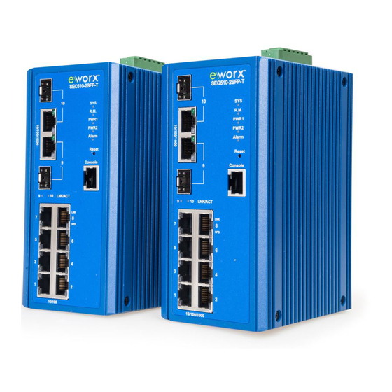
Advantech eWorx SE500 User Manual (209 pages)
Brand:
Advantech
| Category:
Switch
| Size: 8.5 MB
Table of Contents
Table of Contents
3
List of Figures
8
List of Tables
14
Declaration of Conformity
20
Product Warranty - Limited Lifetime
22
Product Overview
24
Supported Models
24
Specifications
24
Table 1: Wide Temperature Models
24
Table 2: Specifications
25
Hardware Views
26
Front View
26
Figure 1: Front View
26
Table 3: Front View Table
27
Figure 2: System LED Panel
28
Table 4: System LED Panel
29
Figure 3: System LED Panel
30
Table 5: System LED Panel
31
Rear View
32
Figure 4: Rear View
32
Top View
33
Figure 5: Top View
33
Table 6: Rear View
33
Table 7: Top View
33
Packing List
34
Figure 6: Top View
34
Table 8: Top View
34
2 Switch Installation
35
Installation Guidelines
35
Connecting Hardware
35
Verifying Switch Operation
35
Installing the Switch
36
DIN Rail Mounting
36
Figure 7: Installing the DIN-Rail Mounting Kit
36
Wall-Mounting
37
Figure 8: Removing the DIN-Rail
37
Figure 9: Installing Wall Mount Plates
38
Figure 10: Securing Wall Mounting Screws
39
Figure 11: Wall Mount Installation
39
Installing and Removing SFP Modules
40
Installing SFP Modules
40
Figure 12: Removing the Dust Plug from an SFP Slot
40
Figure 13: Installing an SFP Transceiver
41
Removing SFP Modules
42
Figure 14: Attaching a Fiber Optic Cable to a Transceiver
42
Figure 15: Removing a Fiber Optic Cable to a Transceiver
42
Connecting the Switch to Ethernet Ports
43
RJ45 Ethernet Cable Wiring
43
Figure 16: Removing an SFP Transceiver
43
Table 9: RJ45 Ethernet Wiring for Reference
43
Connecting the Switch to Console Port
44
Figure 17: Ethernet Plug & Connector Pin Position
44
Figure 18: Serial Console Cable
44
Figure 19: DB 9 Pin Position
44
Figure 20: Pin Assignment
45
Table 10: Pin Assignment
45
Power Supply Installation
46
Overview
46
Figure 21: Power Wiring for SE500 Series
46
Considerations
47
Grounding the Device
47
Wiring a Relay Contact
48
Figure 22: Grounding Connection
48
Figure 23: Terminal Receptor for Non-Poe Models
48
Wiring the Power Inputs
49
Figure 24: Terminal Receptor: Relay Contact for Poe Models
49
Figure 25: Terminal Receptor: Power Input Contacts for Non Poe Models
49
Figure 26: Terminal Receptor: Power Input Contacts for Poe Models
50
Figure 27: Removing a Terminal Block
50
Reset Button
51
Figure 28: Installing DC Wires in a Terminal Block
51
Figure 29: Securing a Terminal Block to a Receptor
51
3 Configuration Utility
52
First Time Setup
52
Overview
52
Introduction
52
Administrative Interface Access
53
Using the Graphical (Web) Interface
53
Configuring the Switch for Network Access
53
Configuring the Ethernet Ports
55
Command Line Interface Configuration
56
Introduction to Command-Line Interface (CLI)
56
Accessing the CLI
56
Web Browser Configuration
57
Preparing for Web Configuration
57
System Login
57
4 Managing the Switch
58
Log in
58
Recommended Practices
58
Figure 30: Login Screen
58
Changing Default Password
59
Figure 31: Changing a Default Password
59
Monitoring
60
Device Information
60
Figure 32: Monitoring > Device Information
60
Table 11: Monitoring > Device Information
61
Logging Message
62
Figure 33: Monitoring > Logging Message
62
Table 12: Monitoring > Logging Message
63
Port Monitoring
64
Figure 34: Monitoring > Port Monitoring > Port Statistics
64
Table 13: Monitoring > Port Monitoring > Port Statistics
64
Link Aggregation
65
LLDP Statistics
65
Figure 35: Monitoring > Port Monitoring > Port Utilization
65
Table 14: Monitoring > Port Monitoring > Port Utilization
65
Figure 36: Monitoring > LLDP Statistics
66
Table 15: Monitoring > LLDP Statistics
66
IGMP Statistics
67
Table 16: Monitoring > IGMP Statistics
67
System
68
IP Settings
68
Figure 37: System > IP Settings
68
Table 17: Monitoring > IGMP Statistics
68
DHCP Client Option 82
69
Table 18: System > IP Setting
69
Figure 38: System > DHCP Client Option 82
70
DHCP Auto Provision
71
Table 19: System > DHCP Client Option 82
71
Figure 39: System > DHCP Auto Provision
72
Table 20: System > DHCP Auto Provision
72
Ipv6 Settings
73
Table 21: System > Ipv6 Settings
73
Management VLAN
74
Figure 40: System > Management VLAN
74
Table 22: System > Ipv6 Settings
74
Table 23: System > Management VLAN
75
System Time
76
Table 24: System > System Time
76
Table 25: System > System Time
77
L2 Switching
78
Port Configuration
78
Figure 41: L2 Switching > Port Configuration
78
Port Mirror
79
Table 26: L2 Switching > Port Configuration
79
Table 27: L2 Switching > Port Mirror
80
Table 28: L2 Switching > Port Mirror
80
Link Aggregation
81
Figure 42: L2 Switching > Link Aggregation > Load Balance
81
Table 29: L2 Switching > Link Aggregation > Load Balance
81
Figure 43: L2 Switching > Link Aggregation > LAG Management
82
Figure 44: L2 Switching > Link Aggregation > LAG Port Settings
83
Table 30: L2 Switching > Link Aggregation > LAG Management
83
Figure 45: L2 Switching > Link Aggregation > LACP Priority Settings
84
Table 31: L2 Switching > Link Aggregation > LAG Port Settings
84
Figure 46: L2 Switching > Link Aggregation > LACP Port Settings
85
Table 32: L2 Switching > Link Aggregation > LACP Priority Settings
85
Q Vlan
86
Table 33: L2 Switching > Link Aggregation > LACP Port Settings
86
Figure 47: L2 Switching > 802.1Q VLAN > VLAN Management
87
Table 34: L2 Switching > 802.1Q VLAN > VLAN Management
87
Figure 48: L2 Switching > 802.1Q VLAN > PVID Settings
88
Table 35: L2 Switching > 802.1Q VLAN > PVID Settings
89
Figure 49: L2 Switching > 802.1Q VLAN > Port to VLAN
90
Q-In-Q
91
Table 36: L2 Switching > 802.1Q VLAN > Port to VLAN
91
Figure 50: L2 Switching > Q-In-Q > Global Settings
92
Table 37: L2 Switching > Q-In-Q > Global Settings
92
Figure 51: L2 Switching > Q-In-Q > Port Settings
93
Table 38. L2 Switching > Q-In-Q > Global Settings
93
Table 39: L2 Switching > Q-In-Q > Port Settings
94
Garp
95
Table 40. L2 Switching > Q-In-Q > Port Settings
95
Figure 52: L2 Switching > GARP > GARP Settings
96
Table 41: L2 Switching > GARP > GARP Settings
97
Az EEE
98
Figure 53: L2 Switching > GARP > GVRP Settings
98
Table 42: L2 Switching > GARP > GVRP Settings
98
Figure 54: L2 Switching > 802.3Az EEE
99
Table 43: L2 Switching > 802.3Az EEE
99
Multicast
100
Figure 55: L2 Switching > Multicast > Multicast Filtering
100
Table 44: L2 Switching > Multicast > Multicast Filtering
100
Figure 56: L2 Switching > Multicast > IGMP Snooping > IGMP Settings
101
Table 45: L2 Switching > Multicast > IGMP Snooping > IGMP Settings
101
Figure 57: L2 Switching > Multicast > IGMP Snooping > IGMP Querier
102
Table 46: L2 Switching > Multicast > IGMP Snooping > IGMP Querier
102
Figure 58: L2 Switching > Multicast > IGMP Snooping > IGMP Static Groups
103
Table 47: L2 Switching > Multicast > IGMP Snooping > IGMP Static Groups
103
Figure 59: L2 Switching > Multicast > MLD Snooping > MLD Settings
104
Table 48: L2 Switching > Multicast > MLD Snooping > MLD Settings
104
Figure 60: L2 Switching > Multicast > MLD Snooping > MLD Querier
105
Table 49: L2 Switching > Multicast > MLD Snooping > MLD Querier
105
Jumbo Frame
106
Figure 61: L2 Switching > Multicast > MLD Snooping > MLD Static Group
106
Table 50: L2 Switching > Multicast > MLD Snooping > MLD Static Group
106
Spanning Tree
107
Figure 62: L2 Switching > Jumbo Frame
107
Table 51: L2 Switching > Jumbo Frame
107
Figure 63: L2 Switching > Spanning Tree > STP Global Settings
108
Table 52: L2 Switching > Spanning Tree > STP Global Settings
108
Figure 64: L2 Switching > Spanning Tree > STP Port Settings
109
Table 53: L2 Switching > Spanning Tree > STP Port Settings
110
Figure 65: L2 Switching > Spanning Tree > STP Bridge Settings
111
Table 54: L2 Switching > Spanning Tree > STP Bridge Settings
111
Figure 66: L2 Switching > Spanning Tree > STP Port Advanced Settings
112
Table 55: L2 Switching > Spanning Tree > STP Port Advanced Settings
112
Figure 67: L2 Switching > Spanning Tree > MST Config Identification
113
Table 56: L2 Switching > Spanning Tree > MST Config Identification
113
Figure 68: L2 Switching > Spanning Tree > MST Instance ID Settings
114
Table 57: L2 Switching > Spanning Tree > MST Instance ID Settings
114
X-Ring Elite
115
Figure 69: L2 Switching > Spanning Tree > MST Instance Priority Settings
115
Table 58: L2 Switching > Spanning Tree > MST Instance Priority Settings
115
Figure 70: L2 Switching > X-Ring Elite > X-Ring Elite Settings
116
Figure 71: L2 Switching > X-Ring Elite > X-Ring Elite Groups
116
Table 59: L2 Switching > X-Ring Elite > X-Ring Elite Settings
116
X-Ring Pro
117
Figure 72: L2 Switching > X-Ring Pro > X-Ring Pro Settings
117
Table 60: L2 Switching > X-Ring Elite > X-Ring Elite Groups
117
Figure 73: L2 Switching > X-Ring Pro > X-Ring Pro Groups > X-Ring Pro Groups Settings
118
Table 61: L2 Switching > X-Ring Pro > X-Ring Pro Settings
118
Figure 74: L2 Switching > X-Ring Pro > X-Ring Pro Groups > Couple Setting
119
Table 62: L2 Switching > X-Ring Pro > X-Ring Pro Groups > X-Ring Pro Groups Settings
119
Loopback Detection
120
Table 63: L2 Switching > X-Ring Pro > X-Ring Pro Groups > Couple Setting
120
Figure 75: L2 Switching > Loopback Detection > Global Settings
121
Table 64: L2 Switching > Loopback Detection > Global Settings
121
Figure 76: L2 Switching > Loopback Detection > Port Settings
122
Table 65: L2 Switching > Loopback Detection > Port Settings
122
MAC Address Table
123
Static MAC
123
Figure 77: MAC Address Table > Static MAC
123
MAC Aging Time
124
Figure 78: MAC Address Table > MAC Aging Time
124
Table 66: MAC Address Table > Static MAC
124
Dynamic Forwarding Table
125
Figure 79: MAC Address Table > Dynamic Forwarding Table
125
Table 67: MAC Address Table > MAC Aging Time
125
Security
126
Storm Control
126
Table 68: MAC Address Table > Dynamic Forwarding Table
126
Figure 80: Security > Storm Control > Global Settings
127
Table 69: Security > Storm Control > Global Settings
127
Figure 81: Security > Storm Control > Port Settings
128
Table 70: Security > Storm Control > Port Settings
129
Port Security
130
Figure 82: Security > Port Security
130
Table 71: Security > Port Security
130
Protected Ports
131
Dos Prevention
131
Figure 83: Security > Protected Ports
131
Table 72: Security > Protected Ports
131
Figure 84: Security > Dos Prevention > Dos Global Settings
132
Table 73: Security > Dos Prevention > Dos Global Settings
133
Figure 85: Security > Dos Prevention > Dos Port Settings
134
Table 74: Security > Dos Prevention > Dos Port Settings
134
Applications
135
Figure 86: Security > Applications > TELNET
135
Table 75: Security > Applications > TELNET
135
Figure 87: Security > Applications > SSH
136
Figure 88: Security > Applications > HTTP
136
Table 76: Security > Applications > SSH
136
Figure 89: Security > Applications > HTTPS
137
Table 77: Security > Applications > HTTP
137
138
138
Table 78: Security > Applications > HTTPS
138
Figure 90: Security > 802.1X > 802.1X Settings
139
Table 79: Security > 802.1X > 802.1X Settings
140
IP Security
141
Figure 91: Security > 802.1X > 802.1X Port Configuration
141
Table 80: Security > 802.1X > 802.1X Port Configuration
141
Figure 92: Security > IP Security > Global Settings
142
Figure 93: Security > IP Security > Entry Settings
142
Table 81: Security > IP Security > Global Settings
142
Qos
143
General
143
Table 82: Security > IP Security > Entry Settings
143
Figure 94: Qos > General > Qos Properties
144
Table 83: Qos > General > Qos Properties
144
Figure 95: Qos > General > Qos Settings
145
Table 84: Qos > General > Qos Settings
145
Figure 96: Qos > General > Qos Scheduling
146
Table 85: Qos > General > Qos Scheduling
147
Figure 97: Qos > General > Cos Mapping
148
Table 86: Qos > General > Cos Mapping
149
Figure 98: Qos > General > DSCP Mapping
150
Table 87: Qos > General > DSCP Mapping
151
Figure 99: Qos > General > IP Precedence Mapping
152
Qos Basic Mode
153
Table 88: Qos > General > IP Precedence Mapping
153
Figure 100: Qos > Qos Basic Mode > Global Settings
154
Figure 101: Qos > Qos Basic Mode > Global Settings
154
Figure 102: Qos > Qos Basic Mode > Port Settings
154
Rate Limit
155
Figure 103: Qos > Rate Limit > Ingress Bandwidth Control
155
Table 89: Qos > Qos Basic Mode > Port Settings
155
Figure 104: Qos > Rate Limit > Egress Bandwidth Control
156
Table 90: Qos > Rate Limit > Ingress Bandwidth Control
156
Figure 105: Qos > Rate Limit > Egress Queue
157
Table 91: Qos > Rate Limit > Egress Bandwidth Control
157
Management
158
Lldp
158
Table 92: Qos > Rate Limit > Egress Queue
158
Figure 106: Management > LLDP > LLDP System Settings
159
Table 93: Management > LLDP > LLDP System Settings
160
Figure 107: Management > LLDP > LLDP Port Settings > LLDP Port Configuration
161
Figure 108: Management > LLDP > LLDP Port Settings > Optional Tlvs Selection
161
Table 94: Management > LLDP > LLDP Port Settings > LLDP Port Configuration
161
Figure 109: Management > LLDP > LLDP Port Settings > VLAN Name TLV VLAN Selection
162
Table 95: Management > LLDP > LLDP Port Settings > Optional Tlvs Selection
162
Figure 110: Management > LLDP > LLDP Remote Device Info
163
Table 96: Management > LLDP > LLDP Port Settings > VLAN Name TLV VLAN Selection
163
Snmp
164
Figure 111: Management > SNMP > SNMP Settings
164
Table 97: Management > LLDP > LLDP Remote Device Info
164
Figure 112: Management > SNMP > SNMP Community
165
Table 98: Management > SNMP > SNMP Settings
165
Table 99: Management > SNMP > SNMP Community
166
Figure 113: Management > SNMP > SNMP User Settings
167
Table 100: Management > SNMP > SNMP User Settings
168
Power over Ethernet
169
Figure 114: Management > SNMP > SNMP Trap
169
Table 101: Management > SNMP > SNMP Trap
169
Figure 115: Management > Power over Ethernet > Poe System Settings
170
Table 102: Available POE Switches
170
Table 103: Management > Power over Ethernet > Poe System Settings
171
Figure 116: Management > Power over Ethernet > Poe Port Settings
172
Table 104: Management > Power over Ethernet > Poe Port Settings
173
TCP Modbus
174
Figure 117: Management > TCP Modbus > TCP Modbus Settings
174
Table 105: Management > TCP Modbus > TCP Modbus Settings
174
DHCP Server
175
Figure 118: Management > DHCP Server > Status Settings
175
Table 106: Management > DHCP Server > Status Settings
175
Figure 119: Management > DHCP Server > Global Settings
176
Table 107: Management > DHCP Server > Global Settings
177
Figure 120: Management > DHCP Server > Port Settings
178
Table 108: Management > DHCP Server > Port Settings
178
Figure 121: Management > DHCP Server > Option 82 Settings
179
Table 109: Management > DHCP Server > Option 82 Settings
180
SMTP Client
181
Figure 122: Management > SMTP Client > Global Settings
181
Table 110: Management > SMTP Client > Global Settings
181
Figure 123: Management > SMTP Client > Profile Settings > Profile Settings
182
Table 111: Management > SMTP Client > Profile Settings > Profile Settings
182
Figure 124: Management > SMTP Client > Profile Settings > Profile Target Mail Settings
183
Table 112: Management > SMTP Client > Profile Settings > Profile Target Mail Settings
183
Figure 125: Management > SMTP Client > Sending Message
184
Table 113: Management > SMTP Client > Sending Message
184
Rmon
185
Figure 126: Management > RMON > Rmon Statistics
185
Figure 127: Management > RMON > RMON History
186
Table 114: Management > RMON > Rmon Statistics
186
Table 115: Management > RMON > RMON History
187
Figure 128: Management > RMON > Rmon Alarm
188
Table 116: Management > RMON > RMON Alarm
189
Figure 129: Management > RMON > RMON Event
190
Table 117: Management > RMON > RMON Event
190
Diagnostics
191
Cable Diagnostics
191
Ping Test
191
Figure 130: Diagnostics > Cable Diagnostics
191
Table 118: Diagnostics > Cable Diagnostics
191
Figure 131: Diagnostics > Ping Test
192
Table 119: Diagnostics > Ping Test
193
Ipv6 Ping Test
194
Figure 132: Diagnostics > Ipv6 Ping Test
194
Table 120: Diagnostics > Ipv6 Ping Test
195
System Log
196
Figure 133: Diagnostics > System Log > Logging Service
196
Table 121: Diagnostics > System Log > Logging Service
196
Figure 134: Diagnostics > System Log > Local Logging
197
Table 122: Diagnostics > System Log > Local Logging
197
Figure 135: Diagnostics > System Log > System Log Server
198
DDM
199
Table 123: Diagnostics > System Log > System Log Server
199
Figure 136: Diagnostics > DDM
200
Figure 137: Diagnostics > DDM
200
Table 124: Diagnostics > DDM
200
Tools
201
IXM
201
Figure 138: Tools > IXM
201
Table 125: Diagnostics > DDM
201
Table 126: Tools > IXM
202
Backup Manager
203
Figure 139: Tools > Backup Manager
203
Upgrade Manager
204
Table 127: Tools > Backup Manager
204
Figure 140: Tools > Upgrade Manager
205
Dual Image
206
Figure 141: Tools > Dual Image
206
Table 128: Tools > Upgrade Manager
206
Save Configuration
207
User Account
207
Figure 142: Tools > User Account
207
Table 129: Tools > Dual Image
207
Reset System
208
Reboot Device
208
Table 130: Tools > User Account
208
Troubleshooting
209
Advantech B+B Smartworx Technical Support
209
Advertisement
Advertisement
Related Products
Advantech B+B SmartWorx SEC410-2SFP
Advantech B+B SmartWorx SEC418-2SFP
Advantech B+B SmartWorx SE408-EI-T
Advantech B+B SmartWorx SE408-PN-T
Advantech B+B SmartWorx SEC410-2SFP-EI-T
Advantech B+B SmartWorx SEC418-2SFP-EI-T
Advantech B+B SmartWorx SEC418-2SFP-PN-T
Advantech B+B SmartWorx SEC418-2SFP-T
Advantech B+B SmartWorx SEC410-2SFP-T
Advantech B+B SmartWorx SEC410-2SFP-PN-T
Advantech Categories
Motherboard
Computer Hardware
Desktop
Touch Panel
Network Router
More Advantech Manuals
Login
Sign In
OR
Sign in with Facebook
Sign in with Google
Upload manual
Upload from disk
Upload from URL