Sign In
Upload
Download
Table of Contents
Contents
Add to my manuals
Delete from my manuals
Share
URL of this page:
HTML Link:
Bookmark this page
Add
Manual will be automatically added to "My Manuals"
Print this page
×
Bookmark added
×
Added to my manuals
Manuals
Brands
Advantech Manuals
Switch
EKI-7710E-2C
User manual
Advantech EKI-7710E-2C User Manual
Eki-7710 series 8fe+2g/8ge+2g combo port l2 managed switch
Hide thumbs
1
2
3
4
5
6
7
Table Of Contents
8
9
10
11
12
13
14
15
16
17
18
19
20
21
22
23
24
25
26
27
28
29
30
31
32
33
34
35
36
37
38
39
40
41
42
43
44
45
46
47
48
49
50
51
52
53
54
55
56
57
58
59
60
61
62
63
64
65
66
67
68
69
70
71
72
73
74
75
76
77
78
79
80
81
82
83
84
85
86
87
88
89
90
91
92
93
94
95
96
97
98
99
100
101
102
103
104
105
106
107
108
109
110
111
112
113
114
115
116
117
118
119
120
121
122
123
124
125
126
127
128
129
130
131
132
133
134
135
136
137
138
139
140
141
142
143
144
145
146
147
148
149
150
151
152
153
154
155
156
page
of
156
Go
/
156
Contents
Table of Contents
Troubleshooting
Bookmarks
Table of Contents
Declaration of Conformity
Document Feedback
Packing List
Safety Instructions
Table of Contents
Product Overview
Chapter 1 Product Overview
Supported Models
Specifications
Hardware Views
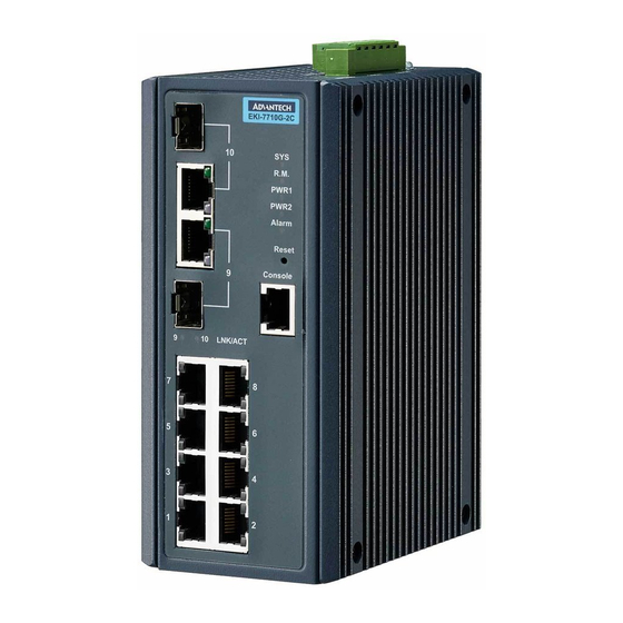
Front View
Figure 1.1 Front View
Figure 1.2 Front View
Figure 1.3 System LED Panel
Figure 1.4 System LED Panel
Rear View
Figure 1.5 Rear View
Top View
Figure 1.6 Top View
Figure 1.7 Top View
Switch Installation
Chapter 2 Switch Installation
Installation Guidelines
Connecting Hardware
Verifying Switch Operation
Installing the Switch
DIN Rail Mounting
Figure 2.1 Installing the DIN-Rail Mounting Kit
Wall-Mounting
Figure 2.2 Removing the DIN-Rail
Figure 2.3 Installing Wall Mount Plates
Figure 2.4 Securing Wall Mounting Screws
Figure 2.5 Wall Mount Installation
Installing and Removing SFP Modules
Installing SFP Modules
Figure 2.6 Removing the Dust Plug from an SFP Slot
Figure 2.7 Installing an SFP Transceiver
Figure 2.8 Attaching a Fiber Optic Cable to a Transceiver
Removing SFP Modules
Figure 2.9 Removing a Fiber Optic Cable to a Transceiver
Figure 2.10 Removing an SFP Transceiver
Connecting the Switch to Ethernet Ports
RJ45 Ethernet Cable Wiring
Figure 2.11 Ethernet Plug & Connector Pin Position
Connecting the Switch to Console Port
Figure 2.12 Serial Console Cable
Figure 2.13 DB 9 Pin Position
Figure 2.14 Pin Assignment
Power Supply Installation
Overview
Considerations
Figure 2.15 Power Wiring for EKI-7710 Series
Grounding the Device
Wiring a Relay Contact
Figure 2.16 Grounding Connection
Figure 2.17 Terminal Receptor: Relay Contact for Non Poe Models
Figure 2.18 Terminal Receptor: Relay Contact for Poe Models
Wiring the Power Inputs
Figure 2.19 Terminal Receptor: Power Input Contacts for Non Poe Models
Figure 2.20 Terminal Receptor: Power Input Contacts for Poe Models
Figure 2.21 Removing a Terminal Block
Figure 2.22 Installing DC Wires in a Terminal Block
Figure 2.23 Securing a Terminal Block to a Receptor
Reset Button
Configuration Utility
Chapter 3 Configuration Utility
First Time Setup
Overview
Introduction
Administrative Interface Access
Using the Graphical (Web) Interface
Configuring the Switch for Network Access
Configuring the Ethernet Ports
Command Line Interface Configuration
Introduction to Command-Line Interface (CLI)
Accessing the CLI
Web Browser Configuration
Preparing for Web Configuration
System Login
Managing Switch
Chapter 4 Managing Switch
Log in
Recommended Practices
Changing Default Password
Figure 4.1 Login Screen
Monitoring
Device Information
Figure 4.2 Changing a Default Password
Figure 4.3 Monitoring > Device Information
Logging Message
Figure 4.4 Monitoring > Logging Message
Port Monitoring
Figure 4.5 Monitoring > Port Monitoring > Port Statistics
Link Aggregation
LLDP Statistics
Figure 4.6 Monitoring > Port Monitoring > Port Utilization
IGMP Statistics
Figure 4.7 Monitoring > LLDP Statistics
Figure 4.8 Monitoring > IGMP Statistics
System
IP Settings
Figure 4.9 System > IP Settings
DHCP Client Option 82
Figure 4.10 System > DHCP Client Option 82
DHCP Auto Provision
Ipv6 Settings
Figure 4.11 System > DHCP Auto Provision
Figure 4.12 System > Ipv6 Settings
Management VLAN
Figure 4.13 System > Management VLAN
System Time
Figure 4.14 System > System Time
L2 Switching
Port Configuration
Figure 4.15 L2 Switching > Port Configuration
Port Mirror
Link Aggregation
Figure 4.16 L2 Switching > Port Mirror
Figure 4.17 L2 Switching > Link Aggregation > Load Balance
Figure 4.18 L2 Switching > Link Aggregation > LAG Management
Figure 4.19 L2 Switching > Link Aggregation > LAG Port Settings
Figure 4.20 L2 Switching > Link Aggregation > LACP Priority Settings
Q Vlan
Figure 4.21 L2 Switching > Link Aggregation > LACP Port Settings
Figure 4.22 L2 Switching > 802.1Q VLAN > VLAN Management
Figure 4.23 L2 Switching > 802.1Q VLAN > PVID Settings
Figure 4.24 L2 Switching > 802.1Q VLAN > Port to VLAN
Q-In-Q
Figure 4.25 L2 Switching > Q-In-Q > Global Settings
Figure 4.26 L2 Switching > Q-In-Q > Port Settings
Garp
Figure 4.27 L2 Switching > GARP > GARP Settings
Az EEE
Figure 4.28 L2 Switching > GARP > GVRP Settings
Figure 4.29 L2 Switching > 802.3Az EEE
Multicast
Figure 4.30 L2 Switching > Multicast > Multicast Filtering
Figure 4.31 L2 Switching > Multicast > IGMP Snooping > IGMP Settings
Figure 4.32 L2 Switching > Multicast > IGMP Snooping > IGMP Querier
Figure 4.33 L2 Switching > Multicast > IGMP Snooping > IGMP Static Groups
Figure 4.34 L2 Switching > Multicast > MLD Snooping > MLD Settings
Figure 4.35 L2 Switching > Multicast > MLD Snooping > MLD Querier
Figure 4.36 L2 Switching > Multicast > MLD Snooping > MLD Static Group
Jumbo Frame
Spanning Tree
Figure 4.37 L2 Switching > Jumbo Frame
Figure 4.38 L2 Switching > Spanning Tree > STP Global Settings
Figure 4.39 L2 Switching > Spanning Tree > STP Port Settings
Figure 4.40 L2 Switching > Spanning Tree > STP Bridge Settings
Figure 4.41 L2 Switching > Spanning Tree > STP Port Advanced Settings
Figure 4.42 L2 Switching > Spanning Tree > MST Config Identification
Figure 4.43 L2 Switching > Spanning Tree > MST Instance ID Settings
Figure 4.44 L2 Switching > Spanning Tree > MST Instance Priority Settings
X-Ring Elite
Figure 4.45 L2 Switching > X-Ring Elite > X-Ring Elite Settings
Figure 4.46 L2 Switching > X-Ring Elite > X-Ring Elite Groups
X-Ring Pro
Figure 4.47 L2 Switching > X-Ring Pro > X-Ring Pro Settings
Figure 4.48 L2 Switching > X-Ring Pro > X-Ring Pro Groups > X-Ring Pro Groups Settings
Loopback Detection
Figure 4.49 L2 Switching > X-Ring Pro > X-Ring Pro Groups > Couple Setting
Figure 4.50 L2 Switching > Loopback Detection > Global Settings
MAC Address Table
Static MAC
Figure 4.51 L2 Switching > Loopback Detection > Port Settings
MAC Aging Time
Figure 4.52 MAC Address Table > Static MAC
Figure 4.53 MAC Address Table > MAC Aging Time
Dynamic Forwarding Table
Security
Storm Control
Figure 4.54 MAC Address Table > Dynamic Forwarding Table
Figure 4.55 Security > Storm Control > Global Settings
Figure 4.56 Security > Storm Control > Port Settings
Port Security
Figure 4.57 Security > Port Security
Protected Ports
Dos Prevention
Figure 4.58 Security > Protected Ports
Figure 4.59 Security > Dos Prevention > Dos Global Settings
Figure 4.60 Security > Dos Prevention > Dos Port Settings
Applications
Figure 4.61 Security > Applications > TELNET
Figure 4.62 Security > Applications > SSH
Figure 4.63 Security > Applications > HTTP
Figure 4.64 Security > Applications > HTTPS
Figure 4.65 Security > 802.1X > 802.1X Settings
IP Security
Figure 4.66 Security > 802.1X > 802.1X Port Configuration
Figure 4.67 Security > IP Security > Global Settings
Qos
General
Figure 4.68 Security > IP Security > Entry Settings
Figure 4.69 Qos > General > Qos Properties
Figure 4.70 Qos > General > Qos Settings
Figure 4.71 Qos > General > Qos Scheduling
Figure 4.72 Qos > General > Cos Mapping
Figure 4.73 Qos > General > DSCP Mapping
Qos Basic Mode
Figure 4.74 Qos > General > IP Precedence Mapping
Rate Limit
Figure 4.75 Qos > Qos Basic Mode > Global Settings
Figure 4.76 Qos > Qos Basic Mode > Port Settings
Figure 4.77 Qos > Rate Limit > Ingress Bandwidth Control
Figure 4.78 Qos > Rate Limit > Egress Bandwidth Control
Management
Lldp
Figure 4.79 Qos > Rate Limit > Egress Queue
Figure 4.80 Management > LLDP > LLDP System Settings
Figure 4.81 Management > LLDP > LLDP Port Settings > LLDP Port Configuration
Figure 4.82 Management > LLDP > LLDP Port Settings > Optional Tlvs Selection
Figure 4.83 Management > LLDP > LLDP Port Settings > VLAN Name TLV VLAN Selection
Figure 4.84 Management > LLDP > LLDP Local Device Info
Figure 4.85 Management > LLDP > LLDP Remote Device Info
Snmp
Figure 4.86 Management > LLDP > LLDP Overloading
Figure 4.87 Management > SNMP > SNMP Settings
Figure 4.88 Management > SNMP > SNMP Community
Figure 4.89 Management > SNMP > SNMP User Settings
Figure 4.90 Management > SNMP > SNMP Trap
Power over Ethernet
Figure 4.91 Management > Power over Ethernet > Poe System Settings
TCP Modbus
Figure 4.92 Management > Power over Ethernet > Poe Port Settings
DHCP Server
Figure 4.93 Management > TCP Modbus > TCP Modbus Settings
Figure 4.94 Management > DHCP Server > Status Settings
Figure 4.95 Management > DHCP Server > Global Settings
Figure 4.96 Management > DHCP Server > Port Settings
Figure 4.97 Management > DHCP Server > Option 82 Settings
SMTP Client
Figure 4.98 Management > DHCP Server > Lease Entry
Figure 4.99 Management > SMTP Client > Global Settings
Figure 4.100 Management > SMTP Client > Profile Settings > Profile Settings
Figure 4.101 Management > SMTP Client > Profile Settings > Profile Target Mail Settings
Rmon
Figure 4.102 Management > SMTP Client > Sending Message
Figure 4.103 Management > RMON > Rmon Statistics
Figure 4.104 Management > RMON > RMON History
Figure 4.105 Management > RMON > Rmon Alarm
Diagnostics
Cable Diagnostics
Figure 4.106 Management > RMON > RMON Event
Figure 4.107 Diagnostics > Cable Diagnostics
Ping Test
Figure 4.108 Diagnostics > Ping Test
Ipv6 Ping Test
Figure 4.109 Diagnostics > Ipv6 Ping Test
System Log
Figure 4.110 Diagnostics > System Log > Logging Service
Figure 4.111 Diagnostics > System Log > Local Logging
DDM
Figure 4.112 Diagnostics > System Log > System Log Server
Figure 4.113 Diagnostics > DDM
Tools
IXM
Figure 4.114 Diagnostics > DDM
Backup Manager
Figure 4.115 Tools > IXM
Figure 4.116 Tools > Backup Manager
Upgrade Manager
Dual Image
Figure 4.117 Tools > Upgrade Manager
Save Configuration
User Account
Figure 4.118 Tools > Dual Image
Figure 4.119 Tools > User Account
Reset System
Reboot Device
Modbus/Tcp Mapping
Modbus/Tcp Mapping Table
Chapter 5 Troubleshooting
Troubleshooting
Advertisement
Quick Links
Download this manual
User Manual
EKI-7710 Series
8FE+2G/8GE+2G Combo port L2
Managed Switch
Table of
Contents
Previous
Page
Next
Page
1
2
3
4
5
Advertisement
Table of Contents
Need help?
Do you have a question about the EKI-7710E-2C and is the answer not in the manual?
Ask a question
Questions and answers
Related Manuals for Advantech EKI-7710E-2C
Switch Advantech EKI-7710G-2C User Manual
Eki-7710 series 8fe+2g/8ge+2g combo port l2 managed switch (156 pages)
Switch Advantech EKI-7710G-2CP User Manual
Eki-7710 series 8fe+2g/8ge+2g combo port l2 managed switch (156 pages)
Switch Advantech EKI-7710G-2CPI User Manual
Eki-7710 series 8fe+2g/8ge+2g combo port l2 managed switch (156 pages)
Switch Advantech EKI-7716 Series User Manual
8ge+4sfp+4g combo port managed redundant industrial switch (154 pages)
Switch Advantech EKI-7712 Series User Manual
8fe+4g/8ge+4g sfp port l2 managed switch (177 pages)
Switch Advantech EKI-7712G-4F User Manual
8fe+4g/8ge+4g sfp port l2 managed switch (177 pages)
Switch Advantech EKI-7712G-4FP User Manual
8fe+4g/8ge+4g sfp port l2 managed switch (177 pages)
Switch Advantech EKI-7712G-4FPI User Manual
8fe+4g/8ge+4g sfp port l2 managed switch (177 pages)
Switch Advantech EKI-7712G-4FMPI User Manual
8ge + 4g sfp port managed redundant high poe industrial switch (169 pages)
Switch Advantech EKI-7758F User Manual
8g ports industrial managed redundant gigabit ethernet switch, 4 gigabit copper and 4 gigabit sfp (149 pages)
Switch Advantech EKI-7706 Series User Manual
4fe+2g sfp/4ge+2g sfp l2 managed switch (165 pages)
Switch Advantech EKI-7706G User Manual
4fe+2g sfp/4ge+2g sfp l2 managed switch (165 pages)
Switch Advantech EKI-7706E-2F User Manual
4fe+2g sfp/4ge+2g sfp l2 managed switch (165 pages)
Switch Advantech EKI-7720 Series User Manual
(175 pages)
Switch Advantech EKI-7708 Series User Manual
4fe/4ge + 4g sfp port gigabit managed redundant industrial switch 4fe/4ge poe + 4g sfp port gigabit managed redundant industrial poe switch (163 pages)
Switch Advantech EKI-7708G-2SI-AE User Manual
4fe/4ge + 4g sfp port gigabit managed redundant industrial switch, 4fe/4ge poe + 4g sfp port gigabit managed redundant industrial poe switch (157 pages)
This manual is also suitable for:
Eki-7710g-2cp
Eki-7710g-2ci
Eki-7710g-2c
Eki-7710g-2cpi
Eki-7710e-2cpi
Eki-7710e-2cp
...
Show all
Eki-7710e-2ci
Eki-7710 series
Table of Contents
Print
Rename the bookmark
Delete bookmark?
Delete from my manuals?
Login
Sign In
OR
Sign in with Facebook
Sign in with Google
Upload manual
Upload from disk
Upload from URL


Need help?
Do you have a question about the EKI-7710E-2C and is the answer not in the manual?
Questions and answers