Advertisement
Quick Links
Advertisement

Related Manuals for Advantech EKI-8528 Series


Summary of Contents for Advantech EKI-8528 Series
- Page 1 User Manual EKI-8528 Series IEC 61850-3 Managed TSN Switch...
- Page 2 No part of this manual may be reproduced, copied, translated or transmitted in any form or by any means without the prior written permission of Advantech Co., Ltd. Information provided in this manual is intended to be accurate and reliable. How- ever, Advantech Co., Ltd.
- Page 3 Technical Support and Assistance Visit the Advantech web site at www.advantech.com/support where you can find the latest information about the product. Contact your distributor, sales representative, or Advantech's customer service center for technical support if you need additional assistance.
- Page 4 Before setting up the system, check that the items listed below are included and in good condition. If any item does not accord with the table, please contact your dealer immediately. 1 x IEC 61850-3 Managed TSN Switch 2 x Wall-mounting Bracket and Screws EKI-8528 Series User Manual...
- Page 5 The sound pressure level at the operator's position according to IEC 704-1:1982 is no more than 70 dB (A). DISCLAIMER: This set of instructions is given according to IEC 704-1. Advantech disclaims all responsibility for the accuracy of any statements contained herein.
- Page 6 Der arbeitsplatzbezogene Schalldruckpegel nach DIN 45 635 Teil 1000 beträgt 70dB(A) oder weiger. Haftungsausschluss: Die Bedienungsanleitungen wurden entsprechend der IEC- 704-1 erstellt. Advantech lehnt jegliche Verantwortung für die Richtigkeit der in die- sem Zusammenhang getätigten Aussagen ab. EKI-8528 Series User Manual...
- Page 7 Always disconnect the power from the device before servicing it. Before plugging a cable into any port, discharge the voltage stored on the cable by touching the electrical contacts to the ground surface. EKI-8528 Series User Manual...
- Page 8 Contents Chapter Product Overview ........Introduction ......................2 Specifications ...................... 2 Hardware Views ....................5 1.3.1 Front View ....................5 1.3.2 Rear View ....................7 1.3.3 Dimension ....................7 Chapter Switch Installation ........Installation Guidelines ..................9 2.1.1 Connecting Hardware ................9 Verifying Switch Operation ................
- Page 9 PTP......................71 4.4.3 VLANs ....................73 4.4.4 TSN ....................... 75 Maintenance ...................... 81 4.5.1 Restart Device ..................81 4.5.2 Factory Defaults .................. 81 4.5.3 Software ....................81 4.5.4 Configuration ..................82 Chapter Troubleshooting ........Troubleshooting ....................86 EKI-8528 Series User Manual...
- Page 10 Serial Console Cable ......................18 Figure 2.9 DB 9 Pin Position ........................18 Figure 2.10 Pin Assignment ........................18 Figure 2.11 Power Wiring for EKI-8528 Series ..................20 Figure 2.12 Grounding Connection ......................21 Figure 2.13 Terminal Receptor: Relay Contact ..................21 Figure 2.14 Terminal Receptor: Power Input Contacts ................
- Page 11 Firmware Selection ......................... 82 Figure 4.63 Save Running Configuration to Startup-config..............83 Figure 4.64 Download Configuration ......................83 Figure 4.65 Upload Configuration ......................84 Figure 4.66 Activate Configuration ......................84 Figure 4.67 Delete Configuration File ......................84 EKI-8528 Series User Manual...
- Page 12 Chapter Product Overview...
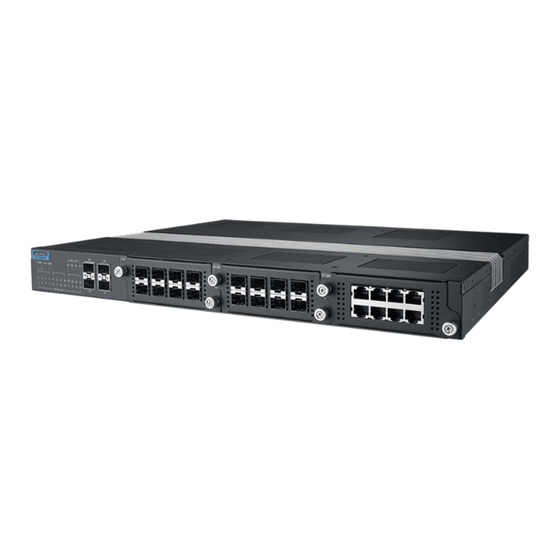
- Page 13 Introduction The EKI-8528 series is a modular, managed Layer 3 and Layer 2 switch designed for standard 19" rackmount installations. It offers up to 24 Gigabit ports and 4x10 Gigabit uplink capabilities, making it ideal for medium to large industrial networking environments.
- Page 14 DHCP DHCP Client / Server DHCP Relay Option 82 Access SNMP v1/v2c/v3 HTTP HTTPS Telnet Standard Configuration HTTP Upload / Down- TFTP load SFTP EKI-8528 Series User Manual...
- Page 15 EN 55032 Class A, EN 61000-6-4, FCC Part 15 Sub- part B Class A EN 61000-4-2 EN 61000-4-3 EN 61000-4-4 EN 61000-4-5 EN 61000-4-6 EN 61000-4-8 Shock IEC 60068-2-27 Freefall IEC 60068-2-32 Vibration IEC 60068-2-6 EN 50121-4 Railway Track Side Substation IEC61850-3, IEEE1613 EKI-8528 Series User Manual...
- Page 16 Front View Figure 1.1 Front View Item Description System LED panel See “System LED Panel” on page 6 for further details. ETH port 4 x 10G SFP+ ports Ethernet Modular Optional 8-port copper or fiber modular Slot EKI-8528 Series User Manual...
- Page 17 Powered down or not installed PWR2 Solid green Powered up Power down or not installed Solid green System is operating normally System is powered down / system crash / operation initiating Alarm Active when power failure is detected EKI-8528 Series User Manual...
- Page 18 Console cable port to COM port (DB9 male) on computer to RS232 managed switch (RJ45 female). Allows configuration backup and restore IIoT Modular Slot Optional for HSR/PRP modular Power Modular Slot Optional AC or DC power modular EKI-8528 Series User Manual...
- Page 19 1.3.3 Dimension EKI-8528 Series User Manual...
- Page 20 Chapter Switch Installation EKI-8528 Series User Manual...
- Page 21 The other LEDs turn off and return to their operating status. If the switch fails POST, the System LED switches to an amber state. After a successful self-test, power down the switch and disconnect the power cabling. The switch is now ready for installation on its final location. EKI-8528 Series User Manual...
- Page 22 2. Secure the rack mount brackets with the provided screws. Figure 2.1 Installing the Rack Mount Brackets 3. Align the switch with the posts on the rack cabinet. 4. Secure the switch with the provided screws. Figure 2.2 Installing the Switch EKI-8528 Series User Manual...
- Page 23 Position the SFP transceiver with the handle on top, see the following figure. Locate the triangular marking in the slot and align it with the bottom of the trans- ceiver. Insert the SFP transceiver into the slot until it clicks into place. EKI-8528 Series User Manual...
- Page 24 Repeat the previous procedures to install any additional SFP transceivers in the switch. The fiber port is now setup. 2.4.2 Removing SFP Modules To disconnect an LC connector, use the following guidelines: Press down and hold the locking clips on the upper side of the optic cable. EKI-8528 Series User Manual...
- Page 25 Pin 2 Pin 6 Pin 3 Pin 3 Pin 3 Pin 1 Pin 6 Pin 6 Pin 6 Pin 2 Figure 2.7 Ethernet Plug & Connector Pin Position Maximum cable length: 100 meters (328 ft.) for 10/100/1000BaseT. EKI-8528 Series User Manual...
- Page 26 4 Blue 5 Blue/White 6 Green 7 Brown/White 8 Brown RJ45 Female Male Figure 2.10 Pin Assignment Power Supply Installation 2.7.1 Overview Warning! Power down and disconnect the power cord before servicing or wiring the switch. EKI-8528 Series User Manual...
- Page 27 Dual power inputs are supported and allow you to connect a backup power source. Figure 2.11 Power Wiring for EKI-8528 Series EKI-8528 Series User Manual...
- Page 28 Caution! Do not service equipment or cables during periods of lightning activity. Caution! Do not service any components unless qualified and authorized to do EKI-8528 Series User Manual...
- Page 29 Wiring a Relay Contact The following section details the wiring of the relay output. The terminal block on the EKI-8528 Series is wired and then installed onto the terminal receptor located on the EKI-8528 Series. Figure 2.13 Terminal Receptor: Relay Contact...
- Page 30 Insert the positive and negative DC wires into the V+ and V-terminals of PW1. If setting up power redundancy, connect PW2 in the same manner. Figure 2.15 Removing a Terminal Block Tighten the wire-clamp screws to secure the DC wires in place. EKI-8528 Series User Manual...
- Page 31 Figure 2.16 Securing DC Wires in a Terminal Block EKI-8528 Series User Manual...
- Page 32 Reset Button Reset configuration to factory default: Press and hold Reset button for 5 seconds. System reboot: Press and hold Reset button for 2 seconds. Note! Do NOT power off the Ethernet switch when loading default settings. EKI-8528 Series User Manual...
- Page 33 Chapter Configuration Utility...
- Page 34 Secure Shell (SSH). An SNMP interface can be used to read/write many settings. Command Line Interface (CLI) can be used to read/write most settings. Initial setup must be done using an Ethernet connection (recommended) or the serial port. EKI-8528 Series User Manual...
- Page 35 NTP Server: The IP address or domain name of an NTP (Network Time Proto- col) server from which the switch may retrieve the current time at startup. Please note that using a domain name requires that at least one domain name server be configured. EKI-8528 Series User Manual...
- Page 36 The general format of commands is: section parameter [value] where: – section is used to group parameters. EKI-8528 Series User Manual...
- Page 37 A PC also connected to the network is required to connect to the switch and access the interface through a web browser. The required networking information is provided as follows: IP address: 192.168.1.1 Subnet mask: 255.255.255.0 Default gateway: 192.168.1.254 User name: admin Password: admin EKI-8528 Series User Manual...
- Page 38 In the browser’s address bar, type the switch’s default IP address (192.168.1.1). The login screen displays. Enter the user default name and password (admin / admin). Click OK on the login screen to log in. The main interface displays. EKI-8528 Series User Manual...
- Page 39 Chapter Managing Switch...
- Page 40 The Edit User screen displays, click the Change Password drop-down menu and select Yes. In the Password field (maximum length: 32 characters), type in the new pass- word. Re-type the same password in the Password (again) field. EKI-8528 Series User Manual...
- Page 41 Enter a description to identify the physical location of this node. The allowed string length is 0 to 255. Only ASCII characters from 32 to 126 are supported. Click Save to store the settings. Save Reset Click Reset to clear the settings. EKI-8528 Series User Manual...
- Page 42 DNS server, and replies as a DNS resolver to the network client devices. Save Click Save to store the settings. Reset Click Reset to clear the settings. To configure the IP interfaces: Figure 4.5 Configuring IP Interfaces EKI-8528 Series User Manual...
- Page 43 Enter a string to identify the length of a network address must match for qualification in the route (values: 0 to 32 bits respectively 128 for IPv6 routes). Add Interface Click to add a new IP interface entry. To add an IP route: Figure 4.6 Configuring IP Routes EKI-8528 Series User Manual...
- Page 44 Save Click Save to store the settings. Reset Click Reset to clear the settings. 4.3.1.4 Time Zone Configuration To configure Time Zone Configuration, access the page as follows: Navigate to Configuration > System and click Time. EKI-8528 Series User Manual...
- Page 45 The Daylight Saving Time Configuration page is used to set the clock forward or backward according to the configurations set below for a defined Daylight Saving Time duration. To configure the daylight saving time: Figure 4.9 Daylight Saving Time Configuration EKI-8528 Series User Manual...
- Page 46 equal than Notice (5). Informational: Send a specific message(s) if the severity code is less or equal than Informational (6). Save Click Save to store the settings. Reset Click Reset to clear the settings. EKI-8528 Series User Manual...
- Page 47 If speed is set as auto negotiation, the port only advertises the specified speeds (10M 100M 1G 2.5G 5G 10G) to the link partner. By default port will advertise all the supported speeds if speed is set as Auto. EKI-8528 Series User Manual...
- Page 48 Click Save to store the settings. Reset Click Reset to clear the settings. 4.3.3 VLANs 4.3.3.1 Global VLAN Configuration The function allows you to configure VLAN control settings. Navigate to Configuration > VLANs and click Configuration. EKI-8528 Series User Manual...
- Page 49 Enter the string to indicate the ethertype/TPID used for custom s- S-ports ports. The setting is in force for all ports whose Port Type is set to S- Custom-Port. Port VLAN Configuration Port Displays the logical port number for the entry. EKI-8528 Series User Manual...
- Page 50 S-custom-tag aware Ingress filtering can be controlled Ingress acceptance of frames and configuration of egress tagging can be configured independently Port VLAN Enter the string to indicate the port’s VLAD ID (range: 1 to 4095, default 1). EKI-8528 Series User Manual...
- Page 51 This option is only available for ports in Hybrid mode. Allowed VLANs Enter the string to indicate the bound VLAN membership. By default, a Trunk or Hybrid port becomes member of all VLANs, and is therefore set to 1 to 4095. EKI-8528 Series User Manual...
- Page 52 Click Save to create a new user account. Reset Click Reset to clear the settings. 4.3.4 4.3.4.1 Port Classification This function allows you to configure the basic QoS Classification settings for all switch ports. Navigate to Configuration > QoS and click Port Classification. EKI-8528 Series User Manual...
- Page 53 Note: This setting has no effect if the port is VLAN unaware. Tagged frames received on VLAN unaware ports are always classified to the default CoS and DPL. DSCP Based Click to enable or disable (default) the DSCP Based QoS Ingress Port classification. EKI-8528 Series User Manual...
- Page 54 Click Save to create a new user account. Reset Click Reset to clear the settings. 4.3.4.3 Queue Policing This function allows you to configure the Queue Policer settings for all switch ports. Navigate to Configuration > QoS and click Quene Policing. EKI-8528 Series User Manual...
- Page 55 This function provides an overview of QoS Egress Port Schedulers for all switch ports. Navigate to Configuration > QoS and click Port Scheduler. The QoS Egress Port Schedulers page displays. Figure 4.17 QoS Egress Port Schedulers EKI-8528 Series User Manual...
- Page 56 Queue Shaper Rate- Click the drop-down menu to indicate the rate type of the queue type shaper. Options: Line: Specify that this shaper operates on line rate. Data: Specify that this shaper operates on data rate. EKI-8528 Series User Manual...
- Page 57 Displays the shaper rate status: disabled or actual port shaper rate. 4.3.4.6 Port Tag Remarking This function provides an overview of QoS Egress Port Tag Remarking for all switch ports. Navigate to Configuration > QoS and click Port Tag Remarking. EKI-8528 Series User Manual...
- Page 58 Click Cancel to return to the previous menu without saving settings. 4.3.4.7 Port DSCP This function allows you to configure the basic QoS Port DSCP Configuration settings for all switch ports. Navigate to Configuration > QoS and click Port DSCP. EKI-8528 Series User Manual...
- Page 59 Click Reset to undo any changes made locally and revert to previously saved values. 4.3.4.8 DSCP-Based QoS This function allows you to configure the basic QoS DSCP based QoS Ingress Classification settings for all switches. Navigate to Configuration > QoS and click DSCP-Based QoS. EKI-8528 Series User Manual...
- Page 60 4.3.4.9 DSCP Translation This function allows you to configure the basic QoS DSCP Translation settings for all switches. DSCP translation can be done in Ingress or Egress. Navigate to Configuration > QoS and click DSCP Translation. EKI-8528 Series User Manual...
- Page 61 Click Reset to undo any changes made locally and revert to Reset previously saved values. 4.3.4.10 DSCP Classification This function allows you to configure the mapping of CoS and DPL to DSCP value. Navigate to Configuration > QoS and click DSCP Classification. EKI-8528 Series User Manual...
- Page 62 The QoS Ingress Map Configuration page displays. Figure 4.26 QoS Ingress Map Configuration The following table describes the items in the previous figure. Item Description Map ID Displays the map ID for the entry. Click the ID to edit the Ingress map. EKI-8528 Series User Manual...
- Page 63 The QoS Egress Map Configuration page displays. Figure 4.27 QoS Egress Map Configuration The following table describes the items in the previous figure. Item Description Map ID Indicates the Map (unique) ID. Range is 0 to 511. EKI-8528 Series User Manual...
- Page 64 Tag Type Indicates tag type. Possible values are: Any (default): Match tagged and untagged frames. Untagged: Match untagged frames. Tagged: Match tagged frames. C-Tagged: Match C-tagged frames. S-Tagged: Match S-tagged frames. EKI-8528 Series User Manual...
- Page 65 The Storm Policer Configuration page displays. Figure 4.29 Storm Policer Configuration The following table describes the items in the Global Storm Policer Configuration figure. Item Description Frame Type Display the frame type for which the configuration below applies. EKI-8528 Series User Manual...
- Page 66 PTP. When booting the device, it will take some time for a configured PTP application to get locked to the common time reference. It may cause malfunctioning of TAS and PSFP if config-change is issued EKI-8528 Series User Manual...
- Page 67 4.3.5.2 Frame Preemption This function provides an overview of TSN Egress Port Frame Preemption Configuration. Navigate to Configuration > TSN and click Frame Preemption. The Frame Preemption Configuration page displays. Figure 4.32 Frame Preemption Configuration EKI-8528 Series User Manual...
- Page 68 This function allows the user to inspect the current TAS configurations, and possibly change them as well. Navigate to Configuration > TSN > TAS and click Ports. The TAS Configuration Parameters page displays. Figure 4.33 TAS Configuration Parameters EKI-8528 Series User Manual...
- Page 69 Click Reset to undo any changes made locally and revert to previously saved values. 4.3.5.3.2 Max SDU This function allows you to inspect the current TAS configurations, and possibly change them as well. Navigate to Configuration > TSN > TAS and click Max SDU. EKI-8528 Series User Manual...
- Page 70 Flow Meter This function allows you to inspect the current PSFP configurations. Navigate to Configuration > TSN > PSFP and click Flow Meter. The PSFP Flow Meter Configuration page displays. Figure 4.35 PSFP Flow Meter Configuration EKI-8528 Series User Manual...
- Page 71 Stream Enable Click to enable or disable (default) the stream function. Priority Spec Click the drop-down menu to specify a priority value (value: -1 denotes the wild card value; zero or positive values denote priority). EKI-8528 Series User Manual...
- Page 72 Enter an string to indicate the unit used for specifying the administrative cycle time (values: ns, us or ms). Cycle Time Enter an string to indicate the administrative value of the Extension CycleTimeExtension parameter for the gate (value: unsigned integer number of nanoseconds). EKI-8528 Series User Manual...
- Page 73 Displays the individual recovery status. Terminate Strip R-Tag from a frame before presenting it on egress. Enable Enable/disable Latent error detection. Error Diff Displays the latent error detection error difference. Period Displays the latent error detection period. EKI-8528 Series User Manual...
- Page 74 HW Common: Select second DPLL for PTP, Both DPLL have the same (SyncE recovered) clock. Auto: AUTO Select clock control, based on PTP profile and available HW resources. EKI-8528 Series User Manual...
- Page 75 Displays the number of received and transmitted packets per port. Bytes Displays the number of received and transmitted bytes per port. Errors Displays the number of frames received in error and the number of incomplete transmissions per port. EKI-8528 Series User Manual...
- Page 76 Navigate to Monitor > Ports and click QCL Status. The QCL Status page displays. Figure 4.42 QCL Status The following table describes the items in the QCL Status page. Item Description User Displays the QCL user entry. EKI-8528 Series User Manual...
- Page 77 The displayed counters are the totals for receive and transmit, the size counters for receive and transmit, and the error counters for receive and transmit. Navigate to Monitor > Ports and click Detailed Statistics. EKI-8528 Series User Manual...
- Page 78 Figure 4.44 Receive and Transmit Error Counters Table Item Description Rx Drops Displays the number of frames dropped due to lack of receive buffers or egress congestion. Rx CRC/Alignment Displays the number of frames received with CRC or alignment errors. EKI-8528 Series User Manual...
- Page 79 Many Web pages use a port number to express an interface, whereas CLI uses interface names. The table on this page provides a means to convert from one to the other. Navigate to Monitor > Ports and click Name Map. EKI-8528 Series User Manual...
- Page 80 Figure 4.47 PTP External Clock Mode The following table describes the items in the PTP External Clock Mode page. Item Description One_PPS_Mode Displays the name of the interface entry. External Enable Displays the number identifying the port corresponding to the interface. EKI-8528 Series User Manual...
- Page 81 Figure 4.48 802.1AS Clock Instance Specific Statistics Note! The previous figure was distorted to accommodate the current layout. The following table describes the items in the 802.1AS Clock Instance Specific Statistics page. Item Description Clock Click to display the configured values. EKI-8528 Series User Manual...
- Page 82 Click the drop-down menu to select the VLAN users. Options: Admin GVRP RMirror Auto-refresh Check this box to refresh the page automatically. Automatic refresh occurs every 3 seconds. Refresh Click Refresh to refresh the page immediately. EKI-8528 Series User Manual...
- Page 83 Untag UVID Untagged VLAN ID Displays whether Tx Tag is overridden and set to Tag or Untag UVID. The field is empty if not overridden by the selected user. Conflicts Displays whether a port conflict exists (Yes). EKI-8528 Series User Manual...
- Page 84 (FALSE) when the sequence of gate operations has executed a Set-And-Release-MAC operation. Status Verify Displays the status of the MAC Merge sublayer verification for the given device. LocPreemptsupport Displays the value is TRUE when preemption is supported on the port, and FALSE otherwise. EKI-8528 Series User Manual...
- Page 85 Tick Granularity Displays the granularity of the cycle time clock, represented as an unsigned number of tenths of nanoseconds. EKI-8528 Series User Manual...
- Page 86 Figure 4.54 PSFP Stream Filter Status The following table describes the items in the PSFP Stream Filter Status page. Item Description Clear Click to clear the entry for the next Clear operation. SFI ID Displays the stream filter instance ID. EKI-8528 Series User Manual...
- Page 87 Stream Gate Status The function provides an overview of the current PSFP configurations. Navigate to Monitor > TSN > PSFP and click Stream Gate Status. The PSFP SGI Status page displays. Figure 4.56 PSFP SGI Status EKI-8528 Series User Manual...
- Page 88 Figure 4.57 FRER Status The following table describes the items in the FRER Status page. Item Description Instance Displays the FRER instance. Oper Displays the operational state. Green: active Red: disabled or internal error detected. EKI-8528 Series User Manual...
- Page 89 Displays the generation reset counters. Auto-refresh Check this box to refresh the page automatically. Automatic refresh occurs every 3 seconds. Click Refresh to refresh the page immediately. Refresh Click Clear to clear the counters for the selected port. Clear EKI-8528 Series User Manual...
- Page 90 The function allows for the updating of the firmware controlling the switch. Navigate to Maintenance > Software and click Upload. The Software Upload page displays. Click Select File... to browse for a software image and select it. EKI-8528 Series User Manual...
- Page 91 Click Cancel to discontinue activating the backup image. Returns to the previous page. 4.5.4 Configuration 4.5.4.1 Save startup-config The generation of the configuration file may be time consuming, Note! depending on the amount of non-default configuration. EKI-8528 Series User Manual...
- Page 92 If the destination is the running-config, the upload applies to the configuration in one of two methods: – Replace mode: The current configuration is fully replaced with the configura- tion in the uploaded file. – Merge mode: The uploaded file is merged into running-config. EKI-8528 Series User Manual...
- Page 93 Navigate to Maintenance > Configuration and click Delete. The Delete Configuration File page displays. Click a file from the File Name table to select and delete. Click Delete Configuration file to start the process. Figure 4.67 Delete Configuration File EKI-8528 Series User Manual...
- Page 94 Chapter Troubleshooting...
- Page 95 If the LED indicators are normal and the connected cables are correct but pack- ets still cannot be transmitted, please check the user system's Ethernet device configuration or status. EKI-8528 Series User Manual...
- Page 96 No part of this publication may be reproduced in any form or by any means, electronic, photocopying, recording or otherwise, without prior written permis- sion of the publisher. All brand and product names are trademarks or registered trademarks of their respective companies. © Advantech Co., Ltd. 2024...
Need help?
Do you have a question about the EKI-8528 Series and is the answer not in the manual?
Questions and answers