Sign In
Upload
Manuals
Brands
Tektronix Manuals
Portable Generator
DG2040
Tektronix DG2040 Manuals
Manuals and User Guides for Tektronix DG2040. We have
2
Tektronix DG2040 manuals available for free PDF download: User Manual
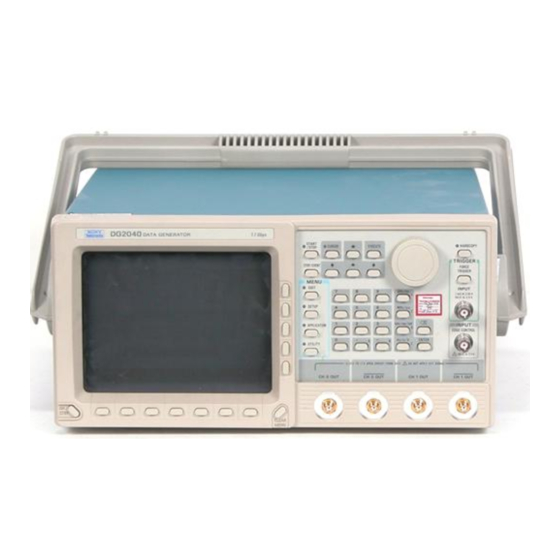
Tektronix DG2040 User Manual (262 pages)
Data Generator
Brand:
Tektronix
| Category:
Portable Generator
| Size: 4 MB
Table of Contents
Table of Contents
6
List of Tables
14
General Safety Summary
16
Service Safety Summary
18
Preface
20
Getting Started
24
Product Description
24
Initial Inspection
25
Options
26
Accessories
27
Power Cord Options
27
Table 1-1: Power Cord Options
27
Table 1-2: Standard Accessories
27
Table 1-3: Optional Accessories
28
Installation
29
Table 1-4: Power Cord Identification
31
Figure 1-1: Rear Panel Power Switch, Fuse Holder, and Connector
32
Power on
32
Standby Power
32
Figure 1-2: Location of the ON/STBY Switch
33
Start-Up Diagnostics
33
Power off
34
Functional Overview
36
Operating Basics
36
Figure 2-1: Front Panel Overview
37
Figure 2-2: Front Panel Controls
38
Figure 2-3: Rear Panel Connectors
39
Figure 2-4: Floppy Disk Drive
40
Figure 2-5: Display Elements
41
Table 2-1: DG2030 Display Elements
42
Figure 2-6: Hardware Block Diagram
43
Theory of Operation
43
Data Structure Overview
45
Figure 2-7: Inhibit Operation Timing
45
Figure 2-8: Data Structures
46
Table 2-2: Data Structure Terms
46
Operating Modes Overview
48
Table 2-3: Run Modes
48
Table 2-4: Update Modes
49
Basic Menu Operation
50
Figure 2-9: Menu and Bezel Buttons
50
Menu Operations
50
Menu Notation
51
Menu Item Display
52
Table 2-5: Bottom Menu Elements
52
Table 2-6: Side and Sub Menu Elements
52
Figure 2-10: DG2030 Front-Panel Keypad
53
Numeric Input
53
Figure 2-11: Numeric Entry in a Menu Item Field
54
Table 2-7: Numeric Input Example
54
Figure 2-12: General Purpose Knob and Arrow Buttons
55
Figure 2-13: Menu Element Knob Icon and Underscore
55
Figure 2-14: Timing Display Format
56
Pattern Data Display Format
56
Figure 2-15: Table Display Format
57
Figure 2-16: Binary Display Format
57
Edit Operations
58
Area and Point Cursors
59
Figure 2-17: Pattern Data Editing Procedure
59
Figure 2-18: Area and Point Cursors
60
Figure 2-19: Text Input Menu
61
Figure 2-20: Popup Message Box
61
Popup Message Box
61
Text Input
61
Menu Trees
62
Operating Examples
66
Required Equipment
66
Before Starting Examples
67
Figure 2-21: Operating Buttons
67
Operating Procedure Sequences
67
Example 1: Creating a Pattern and Storing into a File
68
Figure 2-22: Binary Pattern Creation
70
Example 2: Loading and Editing a Pattern Stored in a File
71
Figure 2 23: Pattern Edited in Example 2
74
Example 3: Signal Output
75
Figure 2-24: Group Data
77
Figure 2-25: Output Assign List and Channel Assignment
79
Figure 2-26: Output Channel Data Bit Allocation
79
Figure 2-27: Rise /Fall Time Settings
81
Figure 2-28: Output Parameter Settings
82
Figure 2-29: DG2030 and Oscilloscope Connection
83
Example 4: Creating a Sequence
84
Figure 2-30: Example 4 Block Sequence
84
Figure 2-31: Block Separation
86
Figure 2-32: Creating a Binary Up-Counter for Block BK1
88
Reference
98
Operation Outlines
99
Creating Pattern Data and Sequences
100
Advanced Control for Sequence
101
Edit Menu
102
Table 3-1: EDIT Menu Functions
102
Edit Display
104
Table 3-2: Edit Menu Display
105
File Menu
106
Load Data & Setup
106
Save Data & Setup
106
Import
107
Table 3-3: Import Parameters
108
CSV Data Format
113
Export
113
Table 3-4: Export Parameters
114
New
115
Place Mark here
116
Settings Menu
116
Select Memory Size
117
Select Arrow Key Function
118
Table 3-5: Arrow Button Functions
119
Table 3-6: Pattern Data Display Format
120
Block Menu
122
Table 3-7: Block Relative Cursor Movement
122
Add Block Delimiter here
123
Delete Current Block Delimiter
124
Rename Current Block
125
Resize Current Block
125
Execute Action Menu
126
Set Scope
128
Copy
129
Cut
129
Paste-Insert
129
Paste-Replace
130
Magnify
133
Numeric Input
134
Table 3-8: Numeric Input Differences
134
Shifting
135
Rotating
137
Creating Standard Pattern Data
138
Table 3-9: Standard Pattern Data Descriptions
138
Clock Pattern
140
Enhanced Action Menu
140
Table 3-10: Parameter Items
141
Shift Register Generator
142
Table 3-11: Shift Register Generator Parameters
143
Logical Operation
145
Table 3-12: Logical Operation Parameters
146
Bit Operation
147
Table 3-13: Bit Operation Parameters
147
Serial Code Converter
148
Table 3-14: Serial Code Converter Parameters
149
Table 3-15: Edit Code Table Parameters
150
Table 3-16: Numeric Key Description
151
Make Sequence Menu
152
Insert
153
Delete
154
Repeat Count
154
Set Enhanced Control
154
Creating and Editing Subsequences
155
Special
155
Limitations on Using Subsequences
156
About Event Jump
157
Undo
158
Setup Menu
160
Table 3-17: SETUP Menu Functions
160
Setup Display
161
Table 3-18: Setup Menu Display
162
Group Assign Menu
163
Add Group
164
Delete Group
164
Group Bit(S) Config
165
Output Condition Menu
165
Rename
165
Reset All Bits Assign
165
Assign Condition
167
Control Condition
167
Table 3-19: Impedance State Contol Methods
168
High
169
Level Condition Menu
169
Low
169
Timing Condition Menu
170
Z on Stop
170
Fall
171
Rise
171
Delay
172
Run Mode Menu
172
Enhanced
174
Repeat
174
Step
174
Update
175
Level
176
Slope
176
Trigger Menu
176
Impedance
177
Interval
177
Source
177
Clock Menu
178
Ext FREQ
178
Int FREQ
178
Source
178
Pll
179
Application Menu
180
Table 3-20: SETUP Menu Functions
182
Utility Menu
182
Change Directory
183
Copy or Delete
183
Make Directory
183
Mass Memory Menu
183
Rename
183
Special
185
Cal Menu
186
Table 3-21: Error Code
186
Display/Hardcopy Menu
187
Display
188
Hardcopy
189
Clear Message Area
190
Remote Port
191
System Menu
191
Gpib
192
Power up Pause
193
Serial
193
Date/Time
194
Reset to Factory
194
Security Immediate
194
Skew Menu
195
Diag Menu
196
Status Display
196
Table 3-22: Error Code
197
Appendix A: Specifications
198
Warranted Characteristics
198
Typical Characteristics
204
Nominal Traits
206
Certification and Compliances
210
Appendix B: Performance Verification
212
Before Running the Operation Tests
213
Test Procedure Notes
215
Self Tests
216
Internal Clock Frequency
218
Performance Tests
218
External Clock Input
221
Sequence & Digital Output
223
Inhibit Function
236
Delay Time Accuracy
244
Appendix C: Miscellaneous
248
Repackaging for Shipment
248
Inspection and Cleaning Procedures
249
Factory Settings
251
Conversion Table Examples
253
Advertisement
Tektronix DG2040 User Manual (256 pages)
Data Generator
Brand:
Tektronix
| Category:
Portable Generator
| Size: 4 MB
Table of Contents
Table of Contents
8
Figure 2-31: Sample Sequence
9
DG2040 Data Generator
21
Table 1-1: Power Cord Options
22
Table 1-2: Power Cord Identification
23
Table 1-3: Standard Accessories
24
Table 1-4: Optional Accessories
25
Table 1-5: Fuse and Fuse Cap Part Numbers
27
Table 1-6: AC Line Power Requirements
27
Figure 1-1: Rear Panel Power Switch, Fuse Holder, and Connector
28
Figure 1-2: Location of the ON/STBY Switch
29
Figure 2-1: Front Panel Controls
33
Figure 2-2: Rear Panel Connectors
35
Figure 2-3: Floppy Disk Drive
36
Figure 2-4: Display Elements
37
Table 2-1: DG2040 Display Elements
38
Figure 2-5: Hardware Block Diagram
39
Figure 2-6: Data Structures
41
Table 2-2: Data Structure Terms
41
Table 2-3: Run Modes
43
Table 2-4: Update Modes
44
Figure 2-7: Menu and Bezel Buttons
45
Table 2-5: Bottom Menu Elements
46
Figure 2-8: DG2040 Front-Panel Keypad
47
Table 2-6: Side and Submenu Elements
47
Figure 2-9: Numeric Entry in a Menu Item Field
48
Table 2-7: Numeric Input Example
48
Figure 2-10: General-Purpose Knob and Arrow Buttons
49
Figure 2-11: Menu Element Knob Icon and Underscore
49
Figure 2-12: Timing Display Format
50
Figure 2-13: Table Display Format
51
Figure 2-14: Binary Display Format
51
Figure 2-15: Numeric Display Format
52
Figure 2-16: Pattern Data Editing Procedure
53
Figure 2-17: Serial/Parallel Editing Mechanism
53
Figure 2-18: Area and Point Cursors
54
Figure 2-19: Text Input Menu
55
Figure 2-20: Pop-Up Message Box
56
Figure 2-21: Operating Buttons
58
Figure 2-22: Binary Pattern Creation
61
Figure 2 23: Pattern Edited in Tutorial 2
64
Figure 2-24: Output Parameter Settings
66
Figure 2-25: DG2040 Data Generator and Oscilloscope Connection
67
Figure 2-26: Tutorial 4 Block Sequence
68
Figure 2-27: Block Separation
70
Figure 2-28: Creating a Binary Up-Counter for Block BK1
72
Figure 2-29: Creating a Binary Down-Counter for Block BK3
73
Figure 2-30: Sample Subsequence
74
Table 3-1: Edit Menu Display
85
Table 3-2: EDIT Menu Functions
90
Table 3-3: Import Parameters
94
Table 3-4: Export Parameters
99
Table 3-5: Arrow Button Functions
104
Table 3-6: Pattern Data Display Format
105
Table 3-7: Block Cursor Movement
111
Table 3-8: Numeric Input Differences
123
Table 3-9: Standard Pattern Data Descriptions
127
Table 3-10: Parameter Items
129
Table 3-11: Shift Register Generator Parameters
131
Table 3-12: Logical Operation Parameters
134
Table 3-13: Bit Operation Parameters
135
Table 3-14: Serial Code Converter Parameters
137
Table 3-15: Edit Code Table Parameters
138
Table 3-16: Numeric Key Description
139
Table 3-17: SETUP Menu Functions
148
Table 3-18: Setup Menu Display
149
Table 3-19: APPLICATION Menu Functions
163
Table 3-20: UTILITY Menu Functions
167
Table 3-21: Error Code
180
Advertisement
Related Products
Tektronix DG2030
Tektronix DG2020A
Tektronix DPO4000B Series
Tektronix DPO72304DX
Tektronix DSA71604C
Tektronix DPO5204
Tektronix DAS9100
Tektronix TEKTOOLS DMM157
Tektronix DTM510
Tektronix DSA71254/B
Tektronix Categories
Test Equipment
Measuring Instruments
Amplifier
Portable Generator
Printer
More Tektronix Manuals
Login
Sign In
OR
Sign in with Facebook
Sign in with Google
Upload manual
Upload from disk
Upload from URL