Sign In
Upload
Manuals
Brands
Tektronix Manuals
Inverter
DG2020A
Tektronix DG2020A Pattern Generator Manuals
Manuals and User Guides for Tektronix DG2020A Pattern Generator. We have
3
Tektronix DG2020A Pattern Generator manuals available for free PDF download: User Manual, Programmer's Manual, Service Manual
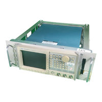
Tektronix DG2020A User Manual (258 pages)
Data Generator
Brand:
Tektronix
| Category:
Laboratory Equipment
| Size: 4 MB
Table of Contents
Table of Contents
6
Figure 1-1: Pod Connection
12
Figure 2-23: Operating Buttons and Menu Layout
12
Figure 2-24: Pod Connection
12
List of Tables
13
General Safety Summary
16
Service Safety Summary
18
Preface
20
Getting Started
22
Product Description
22
Initial Inspection
23
Options
24
Power Cord Options
24
Accessories
25
Table 1-1: Power Cord Options
25
Table 1-2: Standard Accessories
25
Table 1-3: Standard Accessories for Pods
25
Table 1-4: Optional Accessories
26
Table 1-5: Maintenance Kit Contents
27
Installation
28
Figure 1-2: Yellow Index Mark and Yellow Line for Cable Connection
31
Table 1-6: Power Cord Identification
32
Power on
33
Figure 1-3: Rear Panel Controls Used in Start up
33
Figure 1-4: ON/STBY Switch
34
Start-Up Diagnostics
35
Power off
35
Operating Basics
36
Functional Overview
36
Figure 2-1: Front Panel Overall View
37
Figure 2-2: Front Panel Button Detail
38
Figure 2-3: Rear Panel
39
Figure 2-4: Floppy Disk Drive
40
Figure 2-5: Display Elements
41
Table 2-1: DG2030 Display Elements
42
Figure 2-6: P3410 Front Panel and Rear Panel
43
Figure 2-7: P3420 Front Panel and Rear Panel
44
Internal Structure and Operating Principles
45
Figure 2-8: Hardware Block Diagram
45
Figure 2-9: Inhibit Operation Timing
47
Data Structure Basics
48
Table 2-2: Data Structure Terms
49
Figure 2-10: Data Structure Image
50
Operating Modes Overview
51
Table 2-3: Run Modes
51
Table 2-4: Update Modes
51
Figure 2-11: Menu Buttons and Bezel Buttons
52
Menu Notation
53
Menu Item Display
54
Table 2-5: Bottom Menu Item Display
54
Table 2-6: Side and Sub Menu Item Display
54
Numeric Input
55
Basic Menu Operation
52
Menu Operations
52
Figure 2-12: Numeric Keys, Units Button, Delete Key, and Enter Key
55
Figure 2-13: Numeric Input Using the Numeric Keys
56
Table 2-7: Numeric Input Example
56
Figure 2-15: Knob Icon and Underscore
57
Pattern Data Display Format
58
Figure 2-14: General Purpose Knob and Arrow Buttons
57
Figure 2-16: Timing Display Format
58
Figure 2-18: Binary Display Format
59
Edit Operations
60
Area and Point Cursors
61
Figure 2-17: Table Display Format
59
Figure 2-19: Pattern Data Editing Procedure
61
Figure 2-20: Cursor Display in Editing Operations
62
Text Input
63
Pop up Confirmation Windows
63
Figure 2-21: Character Input Menu
63
Figure 2-22: Popup Confirmation Window
64
Menu Trees
65
Basic Operation Examples
70
Required Equipment
70
Before Starting Examples
71
Operating Procedure Sequences
71
Equipment Connections
72
Figure 2-25: Yellow Index Mark and Yellow Line for Cable Connection
73
Example 1: Creating a Pattern and Storing It in a File
74
Figure 2-26: Binary Pattern Creation
76
Example 2: Loading and Editing a Pattern Stored in a File
77
Figure 2 27: Pattern Edited in Example 2
80
Example 3: Signal Output
81
Figure 2-28: Pod Channel Data Bit Allocation
84
Figure 2-29: Output Voltage Level and Delay Time Display for the P3420 Pod
86
Example 4: Creating a Sequence
89
Reference
102
Operation Outlines
103
Outlines for Pattern Data and Sequence Creations
104
Advanced Control for Sequence
105
Edit Menu
106
Table 3-1: Menu Functions
106
CRT Display
108
Table 3-2: Edit Menu Crt Display
109
File Menu
110
Table 3-3: Import Parameters
112
Table 3-4: Export Parameters
117
Settings Menu
118
Table 3-5: Arrow Button Functions
122
Table 3-6: Pattern Data Display Format
124
Block Menu
125
Table 3-7: Block Relative Cursor Movement
125
Execute Action Menu
129
Table 3-8: Numeric Input Differences
137
Table 3-9: Standard Pattern Data Descriptions
141
Enhanced Action Menu
143
Table 3-10: Parameter Items
144
Table 3-11: Shift Register Generator Parameters
146
Table 3-12: Logical Operation Parameters
149
Table 3-13: Bit Operation Parameters
150
Table 3-14: Serial Code Converter Parameters
152
Table 3-15: Edit Code Table Parameters
153
Table 3-16: Numeric Key Description
154
Make Sequence Menu
155
Undo
161
SETUP Menu
162
Table 3-17: Setup Menu Functions
162
CRT Display
164
Table 3-18: Setup Menu CRT Display
165
Group Assign Menu
166
Pod Assign Menu
169
Table 3-19: Impedance State Contol Methods
170
Level/Delay Menu
171
Pod Control Menu
172
Run Mode Menu
174
Trigger Menu
177
Oscillator Menu
178
APPLICATION Menu
180
UTILITY Menu
182
Table 3-20: Menu Functions
183
Mass Memory Menu
184
Display/Hardcopy Menu
187
System Menu
190
Status Menu
194
Diag Menu
194
Table 3-21: Error Code
195
Appendix A: Performance Characteristics
196
Warranted Characteristics
197
Typical Characteristics
202
Nominal Traits
204
Certification and Compliances
209
Appendix B: Performance Verification
212
Before Running the Operation Tests
213
Test Procedure Notes
215
Self Tests
216
Performance Tests for the Dg2020A/Pod Combination
217
P3410 Pod Performance Test
228
P3420 Pod Performance Test
235
Appendix C: Miscellaneous
244
Repackaging for Shipment
244
Inspection and Cleaning Procedures
245
Factory Settings
247
Conversion Table Examples
249
Index
254
Advertisement
Tektronix DG2020A Service Manual (186 pages)
Data Generator
Brand:
Tektronix
| Category:
Inverter
| Size: 2 MB
Table of Contents
Table of Contents
5
General Safety Summary
11
Electrical Parts List
15
Diagrams
15
Manual Conventions
16
Product Description
19
Features
19
Performance Characteristics
21
Warranted Characteristics
22
Table 1-1: Warranted Electrical Characteristics
22
Figure 1-1: Trigger Delay
25
Table 1-2: Warranted Environmental Characteristics
26
Typical Characteristics
27
Table 1-3: Electrical Characteristics (Typical)
27
Nominal Traits
29
Table 1-6: Certifications and Compliances
34
Certification and Compliances
34
Preparation for Use
37
Supplying Power
37
Power Cord Information
38
Table 2-1: Power-Cord Conductor Identification
38
Table 2-2: Power Cord Identification
38
Operating Environment
39
Rear Panel Controls
39
Figure 2-1: Rear Panel Controls
40
Table 2-3: Fuse Type and Rating
40
Applying and Interrupting Power
41
Repackaging Instructions
42
Installed Options
42
Operating Instructions
43
How to Make Connection to Pods
43
Figure 2-2: Pod Connection
43
Figure 2-3: Yellow Index Mark and Yellow Wire for Cable Connection
44
Internal Diagnostics Routines
45
User Interface
45
Figure 2-4: CRT Display
47
Table 2-4: DG2030 Display Elements
48
Menus
49
Pattern Storage and I/O
49
Loading Files
50
Figure 2-5: Load Data & Setup Menu
50
Signal Output
51
Figure 2-6: Operating Buttons and Menu Layout
51
Figure 2-7: Pod Channel Data Bit Allocation
55
Figure 2-8: Output Voltage Level and Delay Time Display for the P3420 Pod
57
Adjustment Procedures
15
Theory of Operation
59
Module Overview
59
Options
61
Performance Verification
63
Introduction
63
Before Running the Operation Tests
64
Table 4-1: Performance Check Disk's File List
64
Table 4-2: Required Equipment
65
Test Procedure Notes
66
Figure 4-1: Operating Buttons and Menu Layout
66
Self Tests
67
Figure 4-2: Diagnostics Menu
67
Table 4-3: Error Codes
67
Performance Tests for the Dg2020A/Pod Combination
68
Figure 4-3: Frequency Measurement Connections
68
Figure 4-4: External Clock Input Connection
70
Table 4-4: Internal Clock Frequency Precision (PLL Off)
70
Figure 4-5: Pod Connection
72
Figure 4-6: P3410 Data Output Connectors
73
Figure 4-7: P3420 Data Output Connectors
73
Figure 4-8: External Trigger Operation Connections
75
Figure 4-9: P3410 Event Input Connections
77
Figure 4-10: P3420 Event Input Connections
77
Figure 4-11: DG2020A Event Output Connections
78
P3410 Pod Performance Test
79
Figure 4-12: Pod Connection
79
Figure 4-13: P3410 Voltage Level Display
80
Figure 4-14: P3410 Output Pins
80
Figure 4-15: Pin Header Cable Types
80
Figure 4-16: Output Voltage Test Connections
81
Figure 4-17: Variable Delay Test Connections
82
Table 4-5: Delay Precision
83
Figure 4-18: Event Input Operation Confirmation Connections
84
Figure 4-19: Inhibit Operation Confirmation Connections
85
P3420 Pod Performance Test
86
Figure 4-20: Pod Connection
86
Figure 4-21: P3420 Voltage Level Display
87
Figure 4-22: P3420 Output Connectors
87
Figure 4-23: Output Voltage Level Measurement Connections
88
Figure 4-24: Variable Delay Precision Check
91
Table 4-8: Delay Precision
92
Figure 4-25: Event Input Operation Confirmation Connections
93
Figure 4-26: Inhibit Input Operation Confirmation Connections
94
Adjustment Procedures
95
Adjustmentprocedure
97
Maintenance
97
Preparation
97
Table 6-1: Relative Susceptibility to Static-Discharge Damage
99
Inspection and Cleaning
100
Table 6-2: External Inspection Check List
101
Table 6-3: Internal Inspection Check List
102
Removal and Installation Procedures
105
Preparation
105
Table 6-4: Equipment Required
106
Figure 6-1: DG2020A Orientation
107
Access Procedure
108
Figure 6-2: Guide to Removal Procedures
108
Figure 6-3: External Modules
109
Figure 6-4: Internal Modules
110
Procedures for External Modules
111
Figure 6-5: Front-Panel Knob Removal
112
Figure 6-6: Line Fuse and Line Cord Removal
113
Figure 6-7: Rear Cover and Cabinet Removal
115
Figure 6-9: Front-Panel Module Removal
119
Figure 6-10: A12 Keyboard Removal
120
Figure 6-11: Disassembly of Front-Panel Module
121
Procedures for Internal Modules
122
Figure 6-12: Connector Module Removal
124
Figure 6-13: Fan and Fan Frame Removal
125
Figure 6-14: Rear Shield Cover Removal
126
Figure 6-15: Power Supply Module Removal
127
Figure 6-16: AUX Power Board and AC Inlet Removal
129
Figure 6-17: Monitor Module Removal
131
Figure 6-18: CRT Frame Removal
132
Figure 6-19: Circuit Boards Removal
135
Figure 6-20: A17 Backplane Board Removal
137
Figure 6-21: Battery Location on the A17 Backplane Board
139
Figure 6-22: Floppy-Disk Drive Module Removal
140
Repackaging
141
Repackaging Instructions
141
Troubleshooting
143
Troubleshooting Procedures
143
DG2020A Diagnostics
143
Figure 6-23: A6 CPU Board
144
Figure 6-24: Primary Troubleshooting Procedure- -(1)
145
Figure 6-25: Primary Troubleshooting Procedure- -(2)
146
Figure 6-26: POD Connector Troubleshooting Procedure
147
Figure 6-27: Troubleshooting Procedure 1 — Power Supply Module
148
Figure 6-28: AUX Power Board
149
Figure 6-29: Power Supply Module
149
Figure 6-30: Troubleshooting Procedure 2 A6 CPU Board or Front-Panel Module
150
Figure 6-31: Key Board
151
Figure 6-32: Troubleshooting Procedure 3 — Monitor Module
152
Figure 6-33: Monitor Module
153
Figure 6-34: Horizontal and Vertical Sync Signals
153
Figure 6-35: a Video Signal with White and Black Levels
154
Figure 6-36: Troubleshooting Procedure 4 — Module Isolation
155
Options and Accessories
157
Options A1- - A5
157
Table 7-1: International Power Cords
157
Option 01 Description
158
Option 02 Description
158
Option 1R Description
158
Option 95 Description
158
P3410 Option 95 Description
159
P3420 Option 95 Description
159
Table 7-2: Standard Accessories
160
Table 7-3: Standard Accessories for Pods
160
Table 7-4: Optional Accessories
161
Table 7-5: Maintenance Kit Contents
162
Electrical Parts List
163
Replaceable Mechanical Parts
169
Parts Ordering Information
169
Using the Replaceable Parts List
170
Beaverton, or
171
Replaceable Parts List
172
Figure 10-7: Option
183
Tektronix DG2020A Programmer's Manual (194 pages)
Data
Brand:
Tektronix
| Category:
Inverter
| Size: 0 MB
Table of Contents
Table of Contents
3
Related Manuals
7
Figure 1-1: Functional Layers in Gpib System
11
Getting Started
11
Table 1-1: GPIB and RS-232-C Comparison
12
Choosing an Interface
12
Figure 1-2: GPIB Connector
13
Installing for GPIB Communication
13
Figure 1-3: GPIB System Configurations
14
Figure 1-4: GPIB Parameter Settings
15
Installing for RS-232-C Communication
16
Figure 1-5: RS-232-C Point-To-Point Connection
16
Figure 1-6: RS-232-C Port
17
Figure 1-7: Pin Assignments of 9-Pin and 25-Pin D-Type Shell Connector
18
Figure 1-8: Typical RS-232-C Cable Wiring Requirements
18
Figure 1-9: RS-232-C Parameter Settings
19
Table 2-1: BNF Symbols and Meanings
23
Command Syntax
23
Figure 2-1: Command and Query Structure Flowchart
24
Syntactic Delimiters
25
Table 2-2: Decimal Numeric Notation
26
Arguments
26
Header
28
Concatenating Commands
30
Table 2-3: Header in Query Responses
31
Other General Command Conventions
32
Table 2-4: DATA Commands
33
Command Groups
33
Table 2-5: DIAGNOSTIC Commands
34
Table 2-6: DISPLAY Commands
35
Table 2-7: HARDCOPY Commands
35
Table 2-8: MEMORY Commands
36
Table 2-9: MODE Commands
36
Table 2-10: OUTPUT Commands
37
Table 2-11: SOURCE Commands
38
Table 2-12: STATUS & EVENT Commands
38
Table 2-13: SYNCHRONIZATION Commands
39
Table 2-14: SYSTEM Commands
39
Command Descriptions
41
Figure 2-2: Abstouch Arguments and Associated Controls
42
Figure 2-3: GPIB: Retrieving Response Messages
135
Figure 2-4: RS-232-C: Retrieving Response Messages
135
Status and Event Reporting
139
Figure 3-1: Standard Event Status (SESR)
140
Table 3-1: SESR Bit Functions
140
Figure 3-2: Status Byte Register (SBR)
141
Table 3-2: SBR Bit Functions
141
Figure 3-3: Device Event Status Enable Register (DESER)
142
Figure 3-4: Event Status Enable Register (ESER)
142
Queues
143
Figure 3-5: Service Request Enable Register (SRER)
143
Processing Sequence
144
Figure 3-6: Status and Event Handling Process Overview
145
Messages
147
Table 3-3: Definition of Event Codes
147
Table 3-4: Normal Condition
148
Table 3-5: Command Errors (CME Bit:5)
148
Table 3-6: Execution Errors (EXE Bit:4)
150
Table 3-7: Internal Device Errors (DDE Bit:3)
152
Table 3-8: System Event and Query Errors
152
Table 3-9: Warnings (EXE Bit:4)
153
Table 3-10: Device-Dependent Command Execution Errors
153
Table 3-11: Extended Device Specific Errors
155
Programming Examples
159
Required Execution Environment
160
Installing and Compiling the Programs
162
Sample Program Functions and Usage
164
Appendix A: Character Charts
173
Table A-1: DG2020A Character Set
173
Table A-2: ASCII & GPIB Code Chart
174
Appendix B: Reserved Words
175
Appendix C: Interface Specification
177
Table C-1: GPIB Interface Function Implementation
177
Table C-2: GPIB Interface Messages
178
Appendix D: Factory Initialization Settings
181
Table D-1: Factory Initialized Settings
181
Advertisement
Advertisement
Related Products
Tektronix DTG5078
Tektronix DTG5274
Tektronix DTG5334
Tektronix DG2030
Tektronix DG2040
Tektronix DPO7354C
Tektronix DAS 9221 Option 04
Tektronix DAS9119
Tektronix DPO72004SX
Tektronix DSA 601A
Tektronix Categories
Test Equipment
Measuring Instruments
Amplifier
Portable Generator
Printer
More Tektronix Manuals
Login
Sign In
OR
Sign in with Facebook
Sign in with Google
Upload manual
Upload from disk
Upload from URL