ProMinent DULCOMETER D1Cb Series Instructions For Assembly And Use
Hide thumbs
Also See for DULCOMETER D1Cb
Series:
- Assembly and operating instructions manual (155 pages)
Table of Contents
Advertisement
Quick Links
Advertisement
Table of Contents

Related Manuals for ProMinent DULCOMETER D1Cb Series


Summary of Contents for ProMinent DULCOMETER D1Cb Series
- Page 1 Instructions for assembly and use DULCOMETER D1Cb ® Please carefully read these operating instructions before use! · Do not discard! The operator shall be liable for any damage caused by installation or operating errors! Technical changes reserved. Part no. 986362 BA DM 176 07/09 EN...
- Page 2 ProMinent Dosiertechnik GmbH Im Schuhmachergewann 5-11 69123 Heidelberg Telephone: +49 6221 842-0 Fax: +49 6221 842-419 email: info@prominent.com Internet: www.prominent.com 986362, 2, en_GB © 2009...
-
Page 3: Table Of Contents
Table of contents Table of contents Introduction ..........................6 Explanation of the Safety Information................6 Users' Qualifications....................... 7 General Safety Information.................... 8 Correct and Proper Use ....................10 ID Code ........................11 Functional Description ......................14 Wall Mounted/Control Panel Mounted ................. 15 Electrical Design ...................... - Page 4 Table of contents Permanent Display 2....................45 Permanent Display 3....................45 Operating Schematics ....................46 Reduced / Complete Operating Menu ................. 48 Fault Messages......................48 5.8.1 Fault display......................49 General settings......................50 5.9.1 Access code......................50 Measured Variables and Operating Menus for Amperometric Sensors ....... 51 Reduced / Complete Operating Menu .................
- Page 5 Table of contents Reduced / Complete Operating Menu ................. 83 Setting the Reading ..................... 84 Description of All Standard Signal Measured Values/Measured Variables ....85 Reduced Operating Menu ................... 86 Complete Operating Menu / Description of All Measured Variables ......88 Calibrating the Standard Signal ...................
-
Page 6: Introduction
Introduction 1 Introduction This operating manual provides information on the technical data and functions of the DULC‐ WARNING! OMETER. ® control series D1Cb. Nature and source of the danger Possible consequence: Fatal or very 1.1 Explanation of the Safety serious injuries. Information Measure to be taken to avoid this danger. -
Page 7: Users' Qualifications
Introduction 1.2 Users' Qualifications NOTICE! Nature and source of the danger WARNING! Damage to the product or its surroundings. Danger of injury with inadequately qualified Measure to be taken to avoid this danger. personnel! If inadequately qualified personnel work on Note! the unit or loiter in the hazard zone of the –... -
Page 8: General Safety Information
Possible consequence: Fatal or very proven training and have been authorised serious injuries by ProMinent to work on the system. – The unit should only be operated by adequately qualified and technically Note for the system operator expert personnel –... - Page 9 Introduction CAUTION! NOTICE! Electronic malfunctions Correct sensor operation / Run-in time Possible consequence: Material damage to Damage to the product or its surroundings destruction of the unit – Correct measuring and dosing is only – The mains connection cable and data possible if the sensor is working cable should not be laid together with perfectly...
-
Page 10: Correct And Proper Use
Introduction 1.4 Correct and Proper Use NOTICE! Compensation for control deviations Damage to the product or its surroundings – The controller can be used in processes, which require compensa‐ tion of > 30 seconds NOTICE! Correct and Proper Use The unit is intended to measure and regu‐ late liquid media. -
Page 11: Id Code
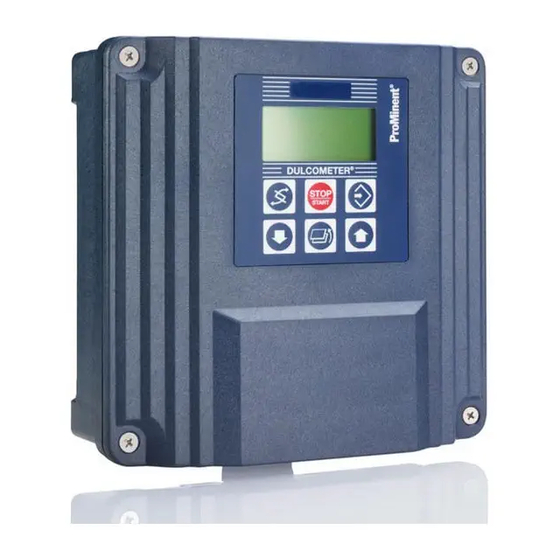
D1Cb ® D1Cb Type of assembly Wall mounted (IP 65) Version 00 with LCD and keypad / with ProMinent logo Operating voltage 90...253 V, 50/60 Hz (wide voltage power unit) Certification 01 CE mark Hardware extension I none... - Page 12 Introduction DULCOMETER control series D1Cb ® Chlorine 0/4...20 mA standard signal general Chlorine dioxide Dissolved oxygen Fluoride Ozone Hydrogen Conductivity peroxide Connection of measured variable mA input (standard signal 0/4-20 mA, all meas‐ ured variables) mV input (pH/redox) Correction variable none Temperature Pt 100/PT1000 (for pH, conductivity, fluoride, CIO...
- Page 13 Introduction DULCOMETER control series D1Cb ® Pump activation none 2 pumps via pulse frequency Control behaviour none Proportional control PID control...
-
Page 14: Functional Description
Functional Description 2 Functional Description Brief functional description The DULCOMETER D1Cb 4-wire measuring transducer/control is a device designed to measure/ ® control a measured variable. In the mA measuring version, the measured variable can be changed without restrictions in the menu of the device. -
Page 15: Wall Mounted/Control Panel Mounted
Functional Description Connection of the measured variable Character Measured variable mV input mA input (Hydrogen peroxide) Chlorite Redox 0/4...20 mA standard signal general Conductivity *with reading transducer Description of the terminal connections for mA and mV: refer to Fig. 11 and Fig. 12 Ä... -
Page 16: Electrical Design
Functional Description 2.2 Electrical Design The device does not have a mains power switch. It is therefore immediately ready for operation once connected to the power supply. The device processes an input signal whilst taking into consideration operator inputs. The result is displayed and made available to other devices via a standard signal. -
Page 17: Block Circuit Diagram
Functional Description 2.2.1 Block circuit diagram NOTICE! Connection of mV or mA sensors The DULCOMETER ® D1Cb is suitable for the connection of mV or mA sensors. It is not possible to connect mV and mA sensors simultaneously. - Page 18 Functional Description Fig. 1: Block circuit diagram...
-
Page 19: Galvanic Isolation
Functional Description 2.2.2 Galvanic Isolation WARNING! Protective low voltage/Mains voltage Possible consequence: Fatal or very serious injuries If relay 1 or 2 is operated with protective low voltage, no mains voltage may be connected to the other relay. 500 Vpp Kontaktausgang 2 / contact output 2 500 Vpp... -
Page 20: Assembly
Assembly 3 Assembly Description Number NOTICE! Half screw connection, complete (set) Installation position and conditions – Ensure that there is unimpeded access M12 x 1.5 screw connection, for operation complete (set) – Secure, low-vibration fixing Assembly material, complete, 3P – Avoid direct sunlight Universal (set) –... -
Page 21: Installation (Wall Mounted)
Assembly 3.2 Installation (Wall Mounted) The device can be installed directly on the wall with the aid of the wall bracket. 8 x 50 mm A0011 Fig. 3: Fixing material for wall mounting 1. 3 x Round head screws 5x45 2. -
Page 22: Installation - Control Panel Mounted (Optional)
Assembly 3.3 Installation - Control Panel Mounted (Optional) CAUTION! Dimensional variations Possible consequence: material damage – Photocopying the punched template can result in dimensional deviations – Use the dimensions shown in Fig. 4 and mark on the control panel ±0.5 3140-3 Fig. - Page 23 Assembly Fig. 5: The material thickness of the control panel must be at least 2 mm to ensure secure fixing 1. 1 x Foam rubber caulk strip d3 2. 6 x Galvanised steel retaining brackets 3. 6 x Galvanised PT cutting screws 4.
-
Page 24: Wall Mounted Installation Of D1Cb (Electrical)
Assembly 3.4 Wall Mounted Installation of D1Cb (Electrical) WARNING! Electrical voltage Possible consequence: Fatal or very serious injuries – The electrical connection to the device should only be made once it has been fitted to the wall or control panel –... -
Page 25: Opening The Device
Assembly 3.4.1 Opening the device A0013 Fig. 6: Opening the device Loosen the 4 captive screws (1). Lift the upper section of the device from the lower section (2). A wide flathead screwdriver may be of assistance. Insert the upper section with both guide rails into the lower section (3 and 4) (parked position) 3.4.2 Electrical Installation (Wall Mounted) - Page 26 Assembly Remove cable sheathing over a sufficient Using a suitable tool, punch out the length threaded holes according to the number of cables ( Æ approx. 4 mm). Fit screw connection (1), pressure ring (2) and seal (3) onto cable –...
-
Page 27: Electrical Installation (Control Panel Mounted)
Assembly Fit lock nut M12x1.5 (6) on the inside Fit screw connection M12x1.5 (5) from the outside and tighten firmly 3.4.3 Electrical Installation (Control Panel Mounted) Proceed as described under "Electrical Installa‐ Ä Chapter 3.4.2 tion (Wall Mounted)". Refer to “... -
Page 28: Installation Of Coaxial Cable To Guard Terminal Xe1
Assembly 3.4.4 Installation of Coaxial Cable to Guard Terminal XE1 CAUTION! Maximum length of the coaxial cable 10 m Incorrect reading due to too long a coaxial cable Possible consequence: Slight or minor injuries, material damage The maximum length of the coaxial cable may not exceed 10 m when using redox or pH sensors. -
Page 29: Cable Cross-Sections And Cable End Sleeves
Assembly optional RC-Schutzbeschaltung D1Cb Programmierschnittstelle RC-protection D1Cb Programming interface Schirmklemme Sicherung 5x20 Ground terminal fuse 5x20 Klemmenanordnung Ausführung Wandgerät Detail Anschluss Koaxialkabel D1Cb Terminal order type wall mounting Detail connection coaxial wire D1Cb Manufacturing coaxial cable for the connection at D1Cb or prefabricates in the variants Konfektionierung Koaxialkabel zum Anschluss an D1Cb oder vorkonfektioniert in den Varianten... -
Page 30: Protective Rc Circuit (Optional)
Assembly 3.4.6 Protective RC Circuit (Optional) A protective RC circuit is recommended for operation with consumers, which present an inductive load (e.g. motor metering pumps or solenoid metering pumps). In these applications a protective RC circuit prevents wear and tear of Ä... -
Page 31: Terminal Wiring Diagram
Assembly 3.4.7 Terminal Wiring Diagram Fig. 10: Terminal layout... - Page 32 Assembly Fig. 11: Terminal diagram with assignment options 1...
- Page 33 Assembly Fig. 12: Terminal diagram with assignment options 2...
- Page 34 Assembly Fig. 13: Protective RC circuit terminal diagram...
-
Page 35: Commissioning
Commissioning 4 Commissioning Start menu during initial commis‐ WARNING! sioning Run-in time of sensors The "Language setting during initial This can result is hazardous incorrect commissioning" menu appears only once. metering Later changes to the operating language Take into consideration run-in times when can then be made via the "General commissioning Settings/Information"... - Page 36 Commissioning NOTICE! Resetting the operating language In the event that a foreign and thus incom‐ prehensible operating language has been set, the DULCOMETER ® D1Cb can be reset to its default setting of "English". If you find yourself in the permanent display 1, then by simultaneously pressing the keys the DULCOMETER ®...
-
Page 37: Selection Of The Measured Variable And Measuring Range
Commissioning 4.1.2 Selection of the Measured Variable and Measuring Range WARNING! Incorrect metering due to incorrect metering range Possible consequence: Fatal or serious injuries – The measuring range of the sensor is essential for the measuring range! – If the assignment of the measuring range is modified, the settings must be checked in all menus –... -
Page 38: Activation Code For Extended Functions
4.2.1 Extended Functions Obtain‐ able with the Activation Code D1Cb software upgrade Extended functions To provide an activation code, ProMinent requires the 10-digit serial number (Srnr) The DULCOMETER D1Cb control unit can be ® and the required software upgrade ident‐... - Page 39 Commissioning NOTICE! Activation code When ordering the activation code, it is imperative that you ensure that the serial number (Srnr) corresponds exactly to that of the DULCOMETER ® D1Cb to be extended. Otherwise a chargeable activa‐ tion code will be provided, which will not work.
- Page 40 Commissioning DULCOMETER D1Cb software upgrade ® D1Ub Software default setting Software preset Default setting - measured variable Universal Peracetic acid Bromine Chlorine Chlorine dioxide Fluoride Hydrogen peroxide Chlorite Redox 0/4-20 mA standard signal general Oxygen Ozone Conductivity Connection of the measured variable Standard signal 0/4-20 mA, all measured variables mV input for pH/redox via guard terminal Correction variable...
- Page 41 Commissioning DULCOMETER D1Cb software upgrade ® Control input none Pause Pause or interference variable flow via frequency Signal output none Analogue signal output 0/4-20 mA Power activation Alarm and 2 limit relays Alarm and 2 solenoid valve relays Pump activation none 2 pumps via pulse frequency Control behaviour...
-
Page 42: Operating Schematics / Display Symbols
Operating Schematics / Display Symbols 5 Operating Schematics / Display Symbols 5.1 Overview of device /Operating elements XXXXX DULCOMETER ® STOP START A0008 Fig. 17: Overview of device /Operating elements Function Description 1. Measured variable Affix the measured variable label here 2. -
Page 43: Display Symbols
Operating Schematics / Display Symbols Function Description 5. UP key To increase a displayed numerical value and to change the variables (flashing display) and to move up in the operating menu 6. DOWN key To lower a displayed numerical value and to change the variables (flashing display) and to move down in the oper‐... -
Page 44: Permanent Display 1
Operating Schematics / Display Symbols Meaning Comment Symbol Solenoid valve 1 activation on Symbol left Solenoid valve 2 activation off Symbol right Solenoid valve 2 activation on Symbol right Stop key pressed Manual metering Fault Reading rises very quickly Trend of reading display Reading rises quickly Trend of reading display Reading rises slowly... -
Page 45: Permanent Display 2
Operating Schematics / Display Symbols 5.4 Permanent Display 2 To set the lower and upper value (3) press The left-hand value will flash and can be set using the keys. Confirm the entry with . Switch between the left-hand and right-hand mea. -
Page 46: Operating Schematics
Operating Schematics / Display Symbols 5.6 Operating Schematics Access code – Access to the setting menu can be blocked with an access code – If the access code has been correctly selected for a setting menu, then all of the other setting menus are also accessible Fundamentally the permanent displays 1 - 3 and the calibration menu are freely acces‐... - Page 47 Operating Schematics / Display Symbols Permanent display 1 Permanent display 2 Permanent display 3 Calibration Calibration notes menu Various Access code, correct Setting menus Parameter Access code setting A0001_GB Fig. 21: Access code The number and scope of the setting menus depends on the design of the device.
-
Page 48: Reduced / Complete Operating Menu
Operating Schematics / Display Symbols T ext 1 Selection 1 T ext 2 Selection 2 T ext 1 Selection 1 T ext 2 Selection 2 A0007_GB Fig. 22: Settable values flash on and off 1. Settable values flash on and off Switch to other settable values by pressing the key. -
Page 49: Fault Messages
Operating Schematics / Display Symbols 5.8 Fault Messages Any fault messages and notes which arise are shown in the bottom line of the permanent display 1. Faults which have to be acknowledged (acknowledging them switches the alarm relay off) are shown by the symbol. -
Page 50: General Settings
Operating Schematics / Display Symbols 5.9 General settings 5.9.1 Access code Access to the setting menu can be prevented by an access code. The DULCOMETER D1Cb is deliv‐ ® ered with the access code "5000". Even if disabled by the access code, the calibration menu remains freely accessible. -
Page 51: Measured Variables And Operating Menus For Amperometric Sensors
Measured Variables and Operating Menus for Amperometric Sensors 6 Measured Variables and Operating Menus for Amperometric Sensors 6.1 Reduced / Complete Operating Menu The DULCOMETER D1Cb allows settings to be made in two different comprehensive menus ® (reduced / complete). All of the parameters of the control unit are preset and can be changed in the complete operating menu. -
Page 52: Reduced Operating Menu
Measured Variables and Operating Menus for Amperometric Sensors Measured variable Default measuring range Hydrogen peroxide 200 ppm Chlorite 0.5 ppm The measuring ranges can be selected in the following ppm increments: 0.5, 2, 5, 10, 20, 50, 100, 200, 1000, 2000, 5000, 10000, 20000. 6.3 Reduced Operating Menu The reduced operating menu allows the key parameters to be set. - Page 53 Measured Variables and Operating Menus for Amperometric Sensors Permanent display 1 0.60 auto.: 30.0 °C mea. val 0.60 ppm Permanent display 2 feed fwd: 70 % only with control ctrlout: 59 % (w = setpoint ) w= 0.60 ppm Permanent display 3 0.60 ppm Positive values of setting variable: Measured value lift Negative values of setting variable: Measured value lower...
-
Page 54: Complete Operating Menu / Description Of All Measured Variables
Measured Variables and Operating Menus for Amperometric Sensors 6.4 Complete Operating Menu / Description of All Measured Variables The complete operating menu allows all controller parameters to be set. The following overview shows the settings that can be selected:... - Page 55 Measured Variables and Operating Menus for Amperometric Sensors Permanent display 1 0.60 auto.: 30.0°C Permanent display 2 mea. val 0.60 ppm feed fwd: 70 % only with control ctrlout: 59 % w= 0.60 ppm (w = setpoint) Permanent display 3 0.60 ppm 10.0 calibration...
-
Page 56: Calibration Of All Amperometric Measured Variables
Measured Variables and Operating Menus for Amperometric Sensors 6.5 Calibration of All Amperometric Measured Variables WARNING! Danger of incorrect metering This can result in hazardous incorrect metering During initial commissioning, the measured variable and the measuring range of the sensor must Ä... -
Page 57: Calibration Of The Sensor For Amperometric Measured Variables
Measured Variables and Operating Menus for Amperometric Sensors Error message Condition Remarks * Zero point low (only with 4 - 20 mA sensors) Repeat calibration in water without metering medium Calibration not possible! > 5 mA Check sensor/cable Zero point high >... -
Page 58: Calibration Of Zero Point And Gradient
Measured Variables and Operating Menus for Amperometric Sensors Calibration of amperometric sensors: gradient (in the reduced and complete operating menu) Necessity of calibrating the zero point The sensor is fitted, flushed with sample water Calibration of the zero point is not generally and connected electrically to the necessary. - Page 59 Measured Variables and Operating Menus for Amperometric Sensors Necessity of calibrating the zero point NOTICE! Calibration of the zero point is not generally Then definitively calibrate the gradient with necessary. Calibration of the zero point is a suitable reference method (e.g. DPD. titra‐ only necessary if the sensor is operated at tion etc.).
-
Page 60: Setting The Reading
Sensors provided by third party providers may have measuring ranges, which deviate from the DULCOMETER D1Cb standard specification. ® In order to adapt a ProMinent sensor to the DULCOMETER ® D1Cb only use the menu to be found Ä Chapter 4.1.2 “Selection of the Measured Variable and Measuring in "General Settings", see... - Page 61 Measured Variables and Operating Menus for Amperometric Sensors The correction variable compensates for the effect of the temperature of the medium on the reading. The correction variable is the tempera‐ ture of the medium to be measured. The temperature of the medium affects the value to be measured.
-
Page 62: Measured Variables And Operating Menus For Potentiometric Sensors
Measured Variables and Operating Menus for Potentiometric Sensors 7 Measured Variables and Operating Menus for Potentiometric Sensors Measured variables: pH, redox, fluoride CAUTION! Influence of temperature on the pH or fluo‐ ride measurement Possible consequence: Slight or minor inju‐ ries, material damage Temperature changes in the sample water lead to a change in the gradient of the cali‐... -
Page 63: Reduced / Complete Operating Menu
Measured Variables and Operating Menus for Potentiometric Sensors 7.1 Reduced / Complete Operating Menu The DULCOMETER ® D1Cb allows settings to be made in two different comprehensive menus (reduced / complete). All of the parameters of the control unit are preset and can be changed in the complete operating menu. -
Page 64: Reduced Ph / Redox / Fluoride Operating Menu
Measured Variables and Operating Menus for Potentiometric Sensors Redox measured variable Typical measuring range Measuring range -1000 mV … + 1000 mV Resolution 1 mV Fluoride measured variable Measuring range Measuring range 0..10 ppm 0..99.99 ppm Resolution 0.01 ppm 7.3 Reduced pH / Redox / Fluoride Operating Menu The reduced operating menu allows the key parameters to be operated. - Page 65 Measured Variables and Operating Menus for Potentiometric Sensors Permanent display 1 7.20 temp.: 33.2 °C Temperature specification only with correction variabl e Permanent display 2 mea. val 7.20 pH feedfwd: 70 % only with control ctrlout: -59 % (w = setpoint ) 7.00 pH Positive values of setting variable: Measured value lift...
-
Page 66: Complete Operating Menu/Description Of Ph / Redox / Fluoride
Measured Variables and Operating Menus for Potentiometric Sensors Fig. 33: Reduced pH / redox / fluoride operating menu (shown with the example of pH) 7.4 Complete Operating Menu/Description of pH / Redox / Fluoride The complete operating menu enables the setting of all parameters of the DULCOMETER ®... - Page 67 Measured Variables and Operating Menus for Potentiometric Sensors Permanent display 1 7.20 temp.: 33.2 °C T emperature indication only with correction variable Permanent display 2 mea. val 7.20 pH feedfwd: 70 % only with control -59 % ctrlout: (w = setpoint) 7.00 pH Permanent display 3 7.20 pH...
-
Page 68: Calibration Of Ph, Redox And Fluoride Sensors
Measured Variables and Operating Menus for Potentiometric Sensors 7.5 Calibration of pH, Redox and When calibration/testing has been completed successfully, all of the error checks relating to the Fluoride Sensors reading are restarted. The DULCOMETER ® D1Cb stores the recorded zero point and gradient data. -
Page 69: Description Of The Calibration Of Ph Sensors
Measured Variables and Operating Menus for Potentiometric Sensors 7.5.1 Description of the Calibration of pH Sensors 7.5.1.1 2-Point Calibration 2-Point Calibration Recommended as the standard method Calibration of pH sensors with temperature as the correction variable When calibrating with temperature as the correction variable, the temperature of the buffer solution must be set in "manual"... - Page 70 Measured Variables and Operating Menus for Potentiometric Sensors Two test containers with a buffer solution are required for calibration. The pH value of the buffer solu‐ tions should be at least 2 ph values apart. The sensor should be rinsed thoroughly with water when changing the buffer solution.
- Page 71 Measured Variables and Operating Menus for Potentiometric Sensors 7.5.1.2 1-Point Calibration One test container with a buffer solution is required for calibration. Select Calibration menu 1-Point Calibration Immerse the sensor in the test container Recommended only for special applications with buffer solution (e.g. pH 7) e.g swimming pool water Move the sensor gently until the pH value displayed no longer changes...
-
Page 72: Calibration Of Ph Sensors. Description Of The Setting Ranges
Measured Variables and Operating Menus for Potentiometric Sensors 7.5.2 Calibration of pH Sensors. Description of the Setting Ranges Setting Possible values Starting value Increment Lower value Upper value Remarks Calibration Reading 0.1 ℃ 0 °C 100 ℃ temperature Buffer values Reading 0.01 pH -1.45 pH... -
Page 73: Testing The Redox Sensor
Measured Variables and Operating Menus for Potentiometric Sensors 7.5.4 Testing the Redox Sensor CAUTION! Correct sensor operation / Run-in time Damage to the product or its surroundings – Correct measuring and metering is only possible if the sensor is working perfectly –... - Page 74 Measured Variables and Operating Menus for Potentiometric Sensors Start test with Test is running. ð A buffer value is suggested once the waiting time has expired. Adjust displayed value of "buffer" (flashing) using to the mV value of the redox buffer solu‐ tion in the test container and confirm the value with The D1Cb displays the status...
-
Page 75: Description Of The Calibration Of Fluoride Sensors
Measured Variables and Operating Menus for Potentiometric Sensors 7.5.4.2 Testing Redox Sensors Buffer Values Tables Table: Possible buffer values Possible values Setting Starting value Increment Lower value Upper value Remarks Buffer values Reading 1 mV -1,500 mV +1,500 mV 185-265 mV 220 mV 425-505 mV 465 mV... - Page 76 Measured Variables and Operating Menus for Potentiometric Sensors 7.5.5.1 Description of the Calibration 7.5.5.1.1 Description of 2-Point Cali‐ of Fluoride Sensors bration for Fluoride Sensors Material required for calibration of fluoride sensors Calibration with temperature as the Two test containers with calibrating solution correction variable A thermometer for measuring in fluids (in When calibrating with temperature as the...
- Page 77 Measured Variables and Operating Menus for Potentiometric Sensors Start the calibration process by pressing Start the calibration process by pressing Calibration is running Calibration is running ð ð Enter the concentration of the calibrating Enter the concentration of the calibrating solution determined using the keys solution determined using the keys into the...
- Page 78 Measured Variables and Operating Menus for Potentiometric Sensors 7.5.5.1.2 1-Point Calibration of the Enter the concentration of the calibrating Fluoride Sensor solution determined using the keys into the Calibration of fluoride. Description of 1-point cali‐ bration DULCOMETER ® D1Cb in ppm One container with a calibrating solution is Confirm the ppm value using required for calibration.
-
Page 79: Temperature Correction Value For Ph And Fluoride Sensors
Measured Variables and Operating Menus for Potentiometric Sensors 7.6 Temperature Correction Value for pH and Fluoride Sensors CAUTION! Influence of temperature on the pH or fluoride measurement Possible consequence: Slight or minor injuries, material damage Temperature changes in the sample water lead to a change in the gradient of the calibration lines (pH, fluoride) and to a displacement of the zero point with pH sensors or the standard potential E with fluoride sensors. - Page 80 Measured Variables and Operating Menus for Potentiometric Sensors Temperature correction value for pH and fluoride sensors Possible values Factory setting Increment Lower value Upper value Manual temperature 25 ℃ 0.1 ℃ 0 ℃ 100 ℃ compensation...
-
Page 81: Measured Variables And Operating Menus For The Standard Signal General
Measured Variables and Operating Menus for the Standard Signal General 8 Measured Variables and Operating Menus for the Standard Signal General 8.1 Explanation of the Standard Adjusting the sensor output signal Signal General The following steps must be taken in order to adapt the DULCOMETER ®... - Page 82 DULCOMETER D1Cb. ® NOTICE! Calibration ProMinent also offers the possibility of one- point or two-point calibration of the "standard signal general" measured vari‐ able. This calibration option should only be used if the manufacturer of the sensor or measuring equipment describes or permits this in the operating manual for the sensor or measuring equipment.
-
Page 83: Changing The Measured Variable
Measured Variables and Operating Menus for the Standard Signal General 8.2 Changing the Measured Variable WARNING! Incorrect metering due to incorrect measured variable Possible consequence: Fatal or serious injuries – The measured variable/measuring range of the sensor is essential for the measured vari‐ able/measuring range! –... -
Page 84: Setting The Reading
Measured Variables and Operating Menus for the Standard Signal General general setting Identcode: alarm relay operating menu operating menu information D1CB xxxxxxxxxx reduced Vxxxxxxxxxx Calib timer english Srnr: xxxxxxxxxxx wash timer 5000 access c.: A0088_GB Fig. 40: Reduced / complete changeover 8.4 Setting the Reading WARNING! Incorrect metering due to incorrect measured variable... -
Page 85: Description Of All Standard Signal Measured Values/Measured Variables
Measured Variables and Operating Menus for the Standard Signal General Range assignment table Possible values Starting value Increment Lower value Upper value Lower signal limit 4 mA 0 mA 4 mA Assigned 0 - 100.0 % 0.1 % -5 % 105 % measuring range* 0 - 20.00 mA... -
Page 86: Reduced Operating Menu
Measured Variables and Operating Menus for the Standard Signal General Possible values Measured vari‐ Increment Lower value Upper value Measuring range* able Flow rate 0.001 m 0.000 m 10.00 m 9.999 m 0.1 m 0.0 m 105.0 m 100 m 1,050 m 1,000 m 0.1 gal/h... - Page 87 Measured Variables and Operating Menus for the Standard Signal General Permanent display 1 0.60 auto.: 30.0 °C mea. val Permanent display 2 0.60 feed fwd: 70 % only with control ctrlout: 59 % (w = setpoint ) w= 0.60 ppm Permanent display 3 0.60 % Positive values of setting variable: Measured value lift...
-
Page 88: Complete Operating Menu / Description Of All Measured Variables
Measured Variables and Operating Menus for the Standard Signal General 8.7 Complete Operating Menu / Description of All Measured Variables The complete operating menu allows all control unit parameters to be set. The following overview shows the settings that can be selected:... - Page 89 Measured Variables and Operating Menus for the Standard Signal General Permanent display 1 auto.: 30.0°C Permanent display 2 mea. val feed fwd: 70 % only with control ctrlout: 59 % w= 0.60 % (w = setpoint) Permanent display 3 65 % calibration zero p.: 4.0 mA...
-
Page 90: Calibrating The Standard Signal
Measured Variables and Operating Menus for the Standard Signal General 8.8 Calibrating the Standard Signal In the reduced operating menu the DULCOMETER ® D1Cb calibrates the zero point. In the complete operating menu the DULCOMETER D1Cb performs a two-point calibration. ®... -
Page 91: Calibration Of The Zero Point Of The Standard Signal General
Measured Variables and Operating Menus for the Standard Signal General During calibration, the DULCOMETER D1Cb sets the actuating outputs to "0". The exception to ® this is if a basic load or a manual actuating variable has been set. This remains active. The mA standard signal outputs are frozen. -
Page 92: Two-Point Calibration Of The Standard Signal General
Measured Variables and Operating Menus for the Standard Signal General Calibration in the reduced operating menu Select the calibration menu. Then press Enter the actual value suitable for the respective measured variable determined using the measuring method with the keys into the DULCOMETER ®... - Page 93 Measured Variables and Operating Menus for the Standard Signal General Calibration in the complete operating menu Select the calibration menu. Then press Confirm prompt with Enter the actual value 1 suitable for the respective measured variable determined using the measuring method with the keys into the DULCOMETER D1Cb.
-
Page 94: Operating Menus Independent Of Measured Variables
Operating Menus Independent of Measured Variables 9 Operating Menus Independent of Measured Variables Operating Menus Independent of Measured Variables This section of the DULCOMETER D1Cb ® describes the operating menus, which are independent of the measured variable. -
Page 95: Pumps
Operating Menus Independent of Measured Variables 9.1 Pumps CAUTION! Observe the operating manual for the pump Possibility of damage to the pump. Faults in the process. – The pump must be set to "External Control" operating mode – Observe the maximum stroke rate for the pump –... -
Page 96: Setting The Relays
Operating Menus Independent of Measured Variables 9.2 Setting the Relays Relay combination Relay 1 and relay 2 can be configured independently of each other. Thus any combination of "Off / Limit / Actuator / MV / Timer" is possible. Possible values Factory setting Increment Lower value... -
Page 97: Setting And Functional Description Of The Relays
Operating Menus Independent of Measured Variables 9.2.1 Setting and Functional Description of the Relays 9.2.1.1 Setting and Functional Description of "Relay Off" only with realy „off“ relay relay adjustment relay1 setting ? relay2 A0224_GB Fig. 47: Relay off The functionality of the relays is switched off. 9.2.1.2 Setting and Functional Description of "Relay Used as a Limit Relay"... - Page 98 Operating Menus Independent of Measured Variables Limit relay used as an actuator Extended functions – The limit relays can also be defined in such a way that they react like an actuator. If, for example, a limit relay is activated, then it is deactivated if the pause contact is closed and for a subsequent time delay t (if t >...
- Page 99 Operating Menus Independent of Measured Variables 9.2.1.5 Setting and Functional Description of "Relay Used as a Solenoid Valve" Only with limit value relay or solenoid valve relay relays relay adjustment solenoid valve 1 solenoid valve 2 ↑ ↓ setting ? relay1: period 10 s...
- Page 100 Operating Menus Independent of Measured Variables 1. Theoretical switching time < min. time Cycle Cycle Cycle min. time theoretical Cycle Cycle Cycle min. time actual A0026_GB Fig. 54: Theoretical switching time < min. time The DULCOMETER ® D1Cb does not switch on for a certain number of cycles until the sum of the theoretical switching times exceeds the "min.
-
Page 101: Setting The Limit Values
Operating Menus Independent of Measured Variables 9.3 Setting the Limit Values limits fault limit 2 upper limits hyst.: 4.0 ppm 150.0 ppm setting ? ∆t on: limit 1 lower control: 10.0 ppm relay 1 relay 2 - active closed - active closed ∆... - Page 102 Operating Menus Independent of Measured Variables Possible values Factory setting Increment Lower value Upper value Remarks Control time 9999 s Results in limits ∆ t on message and alarm, Off = 0 s, function switched off message, no alarm Control Limit value 1 Active closed Active closed /...
- Page 103 Operating Menus Independent of Measured Variables Measured value Upper limit value "Hysteresis“ "Hysteresis" Lower limit value Limit value transgression A0009_GB Fig. 57: Hysteresis If the relays are defined as limit relays, they will also switch to the alarm relay when a limit is trans‐ gressed and the direction of the limit transgression will be shown on the display by the symbols Different on-delays (∆t On) and fall-delays (∆t Off) can be set for the limit relays for limit 1 and limit 2.
-
Page 104: Setting The Control
Operating Menus Independent of Measured Variables 9.4 Setting the Control manuel dosing control control 10 % setting ? regulated value regulated positiv ↑ negativ ↓ set point 0.60 ppm PID-control ctrl parameter normal 10 % xp = control value Ti = set point 2 upper Td = 0.60 ppm... - Page 105 Operating Menus Independent of Measured Variables Possible values Factory Increment Lower value Upper value Remarks setting as the actuating vari‐ able for read‐ ings within the dead zone. Set point 0.5 * meas‐ depending on lower limit of upper limit of Set points are uring range the measured...
-
Page 106: Setting The Interference Variable
Operating Menus Independent of Measured Variables 9.5 Setting the Interference Variable pause / feedfwd: pause / feedfwd: feedforward ctrl feedforward ctrl setting function rated value: disturb. variable additive 10.00 Hz feedforward ctrl feedforward ctrl max. additive pause / feedfwd: multiplicative regulated value function 100 %... -
Page 107: Setting The Standard Signal Output
Operating Menus Independent of Measured Variables Possible values Factory setting Increment Lower value Upper value Remarks Maximum limit of range used Interference additive multiplica‐ variable: tive / additive interference effect Max. addi‐ 100 % -100 % +100 % Only with additive tive actuating variable actuating... - Page 108 Operating Menus Independent of Measured Variables Setting values of the standard signal output Possible values Factory setting Increment Lower value Upper value Remarks Assignment Reading Reading of variable Actuating Possible if variable control unit present Correction Only available value with correction variable Range 0 –...
-
Page 109: General Settings
Operating Menus Independent of Measured Variables 9.7 General Settings general setting identcode alarm relay operating menu information D1CBxxxxxxxxxx pause reduced Vxxxxxxxxxxx operating menu English Srnr: xxxxxxxxxx Calib timer access c.: 5000 A0016_GB Fig. 61: General Settings The functions described below can be selected in this menu. 9.7.1 Setting the Measured Variable/Measuring Range WARNING! -
Page 110: Sub-Functions Of The "General Settings" Menu
Operating Menus Independent of Measured Variables In the "Change measured variable" setting range, it is possible to select the measured variable required for the respective process and suitable for the sensor or measuring device. Depending on the meas‐ ured variable, different setting windows have to be completed, which are provided by the DULCOMETER D1Cb software. - Page 111 Operating Menus Independent of Measured Variables 9.7.2.7 Calibration Logbook "Snooze" mode: if the washing timer has expired, the message on the display can be The data on the successfully completed sensor acknowledged for a period of 15 minutes by calibrations are stored in the internal calibration pressing the button.
- Page 112 Operating Menus Independent of Measured Variables Overload/short circuit at mA sensor input If alarm relay "active" has been selected in the "Pause" menu item and pause is active 9.7.2.10 Sensor Monitoring (pH Sensor mV Only) With configured pH measured variables, it is possible to monitor a sensor connected to the potentiometric input for fault statuses.
-
Page 113: Maintenance
Maintenance 10 Maintenance The DULCOMETER ® D1Cb is maintenance free. NOTICE! Use only 5 x 20 mm micro-fuses 10.1 Fuse Change on DULCOM‐ Possible consequence: Damage to the ETER D1Cb ® product or its surroundings – Ä Table on page 123 100 –... -
Page 114: Summary Of Error Texts
Maintenance 10.2 Summary of Error Texts Error Error text Symbol Effect on Effect on Alarm with Remarks actuating control acknowl‐ variable edgement Actuating Check Basic load Stop Function variable sensor can be exceeds switched off control time of reading Upper and Input Basic load Stop... - Page 115 Maintenance Operating Message Symbol Effect on Effect on Alarm with Remarks step text actuating control acknowl‐ variable edgement Pause Pause Stop Stop No/Yes* No further contact error check Pause/Hold Pl frozen Stop key Stop Stop Stop Relays drop During cali‐ Basic load No error bration of...
-
Page 116: Technical Data
Technical Data 11 Technical Data 11.1 DULCOMETER D1Cb ® Permissible ambient conditions: Wall mounted: 0° C – 50° C Control panel 0° C – 50° C mounted: All versions: 10 to 95% relative air humidity (non-condensing) Permissible storage conditions: All versions: -10°... -
Page 117: Material Data
Technical Data 11.3 Material Data Part Material Housing lower and upper section PPE-GF10 Bracket on rear of housing lower section PPE-GF20 Membrane keypad Polyester PET membrane Seal CR foam rubber Angle bracket and screws Galvanically galvanised steel M5 screws Stainless steel A2 11.4 Chemical Resistance The device is resistant to normal atmospheres in plant rooms... -
Page 118: Dimensions And Weights
Technical Data 11.5 Dimensions and Weights Complete device: 198 x 200 x 76 mm (W x H x D) Packaging: 390 x 295 x 155 mm (W x H x D) Weight of device without packaging: approx. 1.2 kg Gross weight of device with packaging: approx. -
Page 119: Electrical Data
Electrical Data 12 Electrical Data Mains connection Nominal voltage range: 100 – 230 VAC ± 10 % Frequency 50 – 60 Hz Current consumption 95 – 250 mA The mains connection is isolated from other switching parts by reinforced insulation. The device has no mains switch;... - Page 120 Electrical Data NOTICE! Do not supply with voltage For the connection of an external semi-conductor or mechanical switch. mA Output Current range: 0/3.8 – 23 mA In the event of a fault: 3.6 or 21.5 mA Max. apparent ohmic resistance: 450 W at 20.5 mA Max.
- Page 121 Electrical Data 2 digital outputs isolated galvanically from each other and from all other connections via OptoMos relays. mA Input Current measuring range 0...24 mA Voltage output for passive transmitters: approx. 21 V/max. 35 mA/ Ri min. 50 W Measuring accuracy: ±...
- Page 122 Electrical Data Not galvanically isolated from the mA and temperature inputs. Terminal for the connection of an elec‐ trode for compensating for the potential of the measuring liquid Temperature input Temperature measuring range: 0...100 °C Measuring flow: approx. 0.96 mA Measuring accuracy: ±...
-
Page 123: Spare Parts And Accessories Dulcometer ® D1Cb
Spare Parts and Accessories DULCOMETER ® D1Cb 13 Spare Parts and Accessories DULCOMETER D1Cb ® Spare Parts Part number Micro-fuse 5x20 T 1.6A 732411 Screw connection M12x1.5 compl. metric 1032245 Half screw connection compl. metric 1031506 Wall bracket 792713 Guard terminal top section (knurled nut) 733389 D1C/D2C measured variable labels 1030506... -
Page 124: Standards Complied With
Standards Complied With 14 Standards Complied With DIN EN 61010 Safety requirements for electrical units for measuring, control, regulating and labo‐ ratory devices DIN EN 61326 Electrical equipment for meas‐ uring, control and laboratory use - EMC require‐ ments (for class A and B devices) DIN EN 55014-1 EMC Requirements of house‐... -
Page 125: Disposal Of Used Parts
Disposal of Used Parts 15 Disposal of Used Parts NOTICE! Regulations governing disposal of used parts – Note the current national regulations and legal standards which apply in your country ProMinent Dosiertechnik, Heidelberg/Germany is prepared to take back clean used parts. -
Page 126: Declaration Of Conformity
Declaration of Conformity 16 Declaration of Conformity Fig. 63: EC Declaration of Conformity... -
Page 127: Index
Index 17 Index Access code..........50 Fixing material ..........21 Activation code ..........38 Foam rubber ..........23 Actuating outputs ........58, 68 Actuator ............. 103 General settings ........109 Air humidity..........116 Ambient conditions........116 Interference variable ......... 106 Cable end sleeves ........ - Page 128 Index Protective low voltage ......... 19 Switching times ......... 100 Punched template ........22 Terminal wiring diagram ......27 Reading ............60 Theoretical switching time ......100 Ribbon cable ..........15 Time delay of limits ........102 Run-in times .......... 58, 68 Timer ............
Need help?
Do you have a question about the DULCOMETER D1Cb Series and is the answer not in the manual?
Questions and answers