Sign In
Upload
Manuals
Brands
Motorola Manuals
Computer Hardware
MPC8260 PowerQUICC II
Motorola MPC8260 PowerQUICC II Manuals
Manuals and User Guides for Motorola MPC8260 PowerQUICC II. We have
1
Motorola MPC8260 PowerQUICC II manual available for free PDF download: User Manual
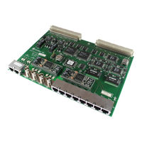
Motorola MPC8260 PowerQUICC II User Manual (1006 pages)
Motorola Processor Users Manual
Brand:
Motorola
| Category:
Computer Hardware
| Size: 10.42 MB
Table of Contents
Table of Contents
5
Features
37
About this Book
55
Before Using this Manualñimportant Note
55
Audience
55
Organization
56
Functional Pinout
56
Suggested Reading
59
Mpc8Xx Documentation
59
Powerpc Documentation
59
Conventions
60
Acronyms and Abbreviations
61
Powerpc Architecture Terminology Conventions
64
Intended Audience
67
Chapter 1 Overview
71
Features
71
Mpc8260Õs Architecture Overview
74
Mpc603E Core
75
System Interface Unit (SIU)
76
Communications Processor Module (CPM)
76
Software Compatibility Issues
77
Signals
77
Differences between MPC860 and MPC8260
79
Serial Protocol Table
79
MPC8260 Configurations
80
Pin Configurations
80
Serial Performance
80
MPC8260 Application Examples
81
Examples of Communication Systems
81
Remote Access Server
81
Regional Office Router
82
LAN-To-WAN Bridge Router
83
Cellular Base Station
84
Telecommunications Switch Controller
84
SONET Transmission Controller
85
Bus Configurations
85
Basic System
85
High-Performance Communication
86
High-Performance System Microprocessor
87
Chapter 2 Powerpc Processor Core
89
Overview
89
Powerpc Processor Core Features
91
Instruction Unit
93
Instruction Queue and Dispatch Unit
93
Branch Processing Unit (BPU)
94
Independent Execution Units
94
Integer Unit (IU)
94
Load/Store Unit (LSU)
95
System Register Unit (SRU)
95
Completion Unit
95
Memory Subsystem Support
96
Memory Management Units (Mmus)
96
Cache Units
96
Programming Model
96
Register Set
96
Powerpc Register Set
97
MPC8260-Specific Registers
99
Hardware Implementation-Dependent Register 0 (HID0)
99
Hardware Implementation-Dependent Register 1 (HID1)
102
Hardware Implementation-Dependent Register 2 (HID2)
103
Processor Version Register (PVR)
104
Powerpc Instruction Set and Addressing Modes
104
Calculating Effective Addresses
104
Powerpc Instruction Set
104
MPC8260 Implementation-Specific Instruction Set
106
Cache Implementation
106
Powerpc Cache Model
106
MPC8260 Implementation-Specific Cache Implementation
107
Data Cache
107
Instruction Cache
109
Cache Locking
109
Entire Cache Locking
109
Way Locking
109
Exception Model
110
Powerpc Exception Model
110
MPC8260 Implementation-Specific Exception Model
111
Exception Priorities
114
Memory Management
114
Powerpc MMU Model
115
MPC8260 Implementation-Specific MMU Features
116
Instruction Timing
117
Differences between the Mpc8260Õs Core and the Powerpc 603E Microprocessor
118
Chapter 3 Memory Map
121
Chapter 4 System Interface Unit (SIU)
139
System Configuration and Protection
140
Bus Monitor
141
Timers Clock
142
Time Counter (TMCNT)
142
Periodic Interrupt Timer (PIT)
143
Software Watchdog Timer
144
Interrupt Controller
145
Interrupt Configuration
146
Interrupt Source Priorities
147
SCC, FCC, and MCC Relative Priority
150
PIT, TMCNT, and IRQ Relative Priority
150
Highest Priority Interrupt
151
Masking Interrupt Sources
151
Interrupt Vector Generation and Calculation
152
Port C External Interrupts
154
Programming Model
155
Interrupt Controller Registers
155
SIU Interrupt Configuration Register (SICR)
155
SIU Interrupt Priority Register (SIPRR)
156
CPM Interrupt Priority Registers (SCPRR_H and SCPRR_L)
157
SIU Interrupt Pending Registers (SIPNR_H and SIPNR_L)
159
SIU Interrupt Mask Registers (SIMR_H and SIMR_L)
160
SIU Interrupt Vector Register (SIVEC)
161
SIU External Interrupt Control Register (SIEXR)
162
System Configuration and Protection Registers
163
Bus Configuration Register (BCR)
164
Bus Arbiter Configuration Register (PPC_ACR)
166
Bus Arbitration-Level Registers (PPC_ALRH/PPC_ALRL)
166
Local Bus Arbitration Level Registers (LCL_ALRH and LCL_ACRL)
168
Internal Memory Map Register (IMMR)
172
System Protection Control Register (SYPCR)
173
Software Service Register (SWSR)
174
X Bus Transfer Error Status and Control Register 1 (TESCR1)
174
X Bus Transfer Error Status and Control Register 2 (TESCR2)
175
Local Bus Transfer Error Status and Control Register 1 (L_TESCR1)
176
Local Bus Transfer Error Status and Control Register 2 (L_TESCR2)
177
Time Counter Status and Control Register (TMCNTSC)
178
Time Counter Register (TMCNT)
179
Time Counter Alarm Register (TMCNTAL)
179
Periodic Interrupt Registers
180
Periodic Interrupt Status and Control Register (PISCR)
180
Periodic Interrupt Timer Count Register (PITC)
181
Periodic Interrupt Timer Register (PITR)
182
SIU Pin Multiplexing
182
Reset Causes
185
Reset Actions
186
Power-On Reset Flow
186
HRESET Flow
187
SRESET Flow
187
Reset Status Register (RSR)
188
Reset Mode Register (RMR)
189
Chapter 5 Reset Configuration
192
Hard Reset Configuration Word
192
Hard Reset Configuration Examples
193
Single MPC8260 with Default Configuration
193
Single MPC8260 Configured from Boot EPROM
194
Multiple Mpc8260S Configured from Boot EPROM
194
Multiple Mpc8260S in a System with no EPROM
196
External Signals
203
Functional Pinout
203
Signal Descriptions
204
Chapter 7
217
Signal Descriptions
217
Address Bus Arbitration Signals
217
Bus Request (Br)Ñoutput
217
Address Bus Request (Br)Ñoutput
217
Address Bus Request (Br)Ñinput
218
Bus Grant (BG)
218
Bus Grant (Bg)Ñinput
218
Bus Grant (Bg)Ñoutput
219
Address Bus Busy (ABB)
219
Address Bus Busy (Abb)Ñoutput
219
Address Bus Busy (Abb)Ñinput
220
Address Transfer Start Signal
220
Transfer Start (TS)
220
Transfer Start (Ts)Ñoutput
220
Transfer Start (Ts)Ñinput
220
Address Transfer Signals
221
Address Bus (A[0Ð31])
221
Address Bus (A[0Ð31])Ñoutput
221
Address Bus (A[0Ð31])Ñinput
221
Address Transfer Attribute Signals
221
Transfer Type (TT[0Ð4])
222
Transfer Type (Tt[0Ð4])Ñoutput
222
Transfer Type (Tt[0Ð4])Ñinput
222
Transfer Size (TSIZ[0Ð3])
222
Transfer Burst (TBST)
222
Global (GBL)
223
Global (Gbl)Ñoutput
223
Global (Gbl)Ñinput
223
Caching-Inhibited (CI)Ñoutput
223
Write-Through (Wt)Ñoutput
223
Address Transfer Termination Signals
224
Address Acknowledge (AACK)
224
Address Acknowledge (Aack)Ñoutput
224
Address Acknowledge (Aack)Ñinput
224
Address Retry (ARTRY)
225
Address Retry (Artry)Ñoutput
225
Address Retry (Artry)Ñinput
225
Data Bus Arbitration Signals
226
Data Bus Grant (DBG)
226
Data Bus Grant (Dbg)Ñinput
226
Data Bus Grant (Dbg)Ñoutput
226
Data Bus Busy (DBB)
227
Data Bus Busy (Dbb)Ñoutput
227
Data Bus Busy (Dbb)Ñinput
227
Data Transfer Signals
227
Data Bus (D[0Ð63])
227
Data Bus (D[0Ð63])Ñoutput
228
Data Bus (D[0Ð63])Ñinput
228
Data Bus Parity (DP[0Ð7])
228
Data Bus Parity (Dp[0Ð7])Ñoutput
228
Data Bus Parity (Dp[0Ð7])Ñinput
229
Data Transfer Termination Signals
229
Transfer Acknowledge (TA)
229
Transfer Acknowledge (Ta)Ñinput
229
Transfer Acknowledge (Ta)Ñoutput
230
Transfer Error Acknowledge (TEA)
230
Transfer Error Acknowledge (Tea)Ñinput
230
Transfer Error Acknowledge (Tea)Ñoutput
231
Partial Data Valid Indication (PSDVAL)
231
Partial Data Valid (Psdval)Ñinput
231
Partial Data Valid (Psdval)Ñoutput
232
Chapter 8 The 60X Bus
233
Terminology
233
Single MPC8260 Bus Mode
234
60X-Compatible Bus Mode
235
Bus Protocol Overview
236
Arbitration Phase
237
Address Pipelining and Split-Bus Transactions
239
Address Tenure Operations
239
Address Arbitration
239
Address Pipelining
241
Address Transfer Attribute Signals
242
Transfer Type Signal (TT[0Ð4]) Encoding
242
Transfer Code Signals TC[0Ð2]
245
TBST and TSIZ[0Ð3] Signals and Size of Transfer
245
Burst Ordering During Data Transfers
246
Effect of Alignment on Data Transfers
246
Effect of Port Size on Data Transfers
248
60X-Compatible Bus Modeñsize Calculation
251
Extended Transfer Mode
252
Address Transfer Termination
255
Address Retried with ARTRY
255
Pipeline Control
258
Data Tenure Operations
258
Data Bus Arbitration
258
Data Streaming Mode
259
Data Bus Transfers and Normal Termination
259
Effect of ARTRY Assertion on Data Transfer and Arbitration
260
Port Size Data Bus Transfers and PSDVAL Termination
260
Data Bus Termination by Assertion of TEA
262
Memory Coherencyñmei Protocol
263
Processor State Signals
264
Support for the Lwarx/Stwcx. Instruction Pair
265
TLBISYNC Input
265
Little-Endian Mode
265
Chapter 9 Clocks and Power Control
267
Clock Unit
267
Clock Configuration
268
External Clock Inputs
271
Main PLL
271
PLL Block Diagram
271
Skew Elimination
272
Clock Dividers
272
The Mpc8260Õs Internal Clock Signals
272
General System Clocks
273
PLL Pins
273
System Clock Control Register (SCCR)
274
System Clock Mode Register (SCMR)
275
Basic Power Structure
276
Chapter 10 Memory Controller
277
Features
279
Basic Architecture
281
Address and Address Space Checking
284
Page Hit Checking
285
Error Checking and Correction (ECC)
285
Parity Generation and Checking
285
Transfer Error Acknowledge (TEA) Generation
285
Machine Check Interrupt (MCP) Generation
285
Data Buffer Controls (Bctlx)
286
Atomic Bus Operation
286
Data Pipelining
286
External Memory Controller Support
287
External Address Latch Enable Signal (ALE)
287
Ecc/Parity Byte Select (PBSE)
287
Partial Data Valid Indication (PSDVAL)
288
Register Descriptions
289
Base Registers (Brx)
290
Option Registers (Orx)
292
SDRAM Mode Register (PSDMR)
297
Local Bus SDRAM Mode Register (LSDMR)
300
Machine A/B/C Mode Registers (Mxmr)
302
Memory Data Register (MDR)
304
Memory Address Register (MAR)
305
Bus-Assigned UPM Refresh Timer (PURT)
306
Local Bus-Assigned UPM Refresh Timer (LURT)
306
Bus-Assigned SDRAM Refresh Timer (PSRT)
307
Local Bus-Assigned SDRAM Refresh Timer (LSRT)
308
Memory Refresh Timer Prescaler Register (MPTPR)
308
Bus Error Status and Control Registers (Tescrx)
309
Local Bus Error Status and Control Registers (L_Tescrx)
309
SDRAM Machine
309
SDRAM Power-On Initialization
311
JEDEC-Standard SDRAM Interface Commands
311
Page-Mode Support and Pipeline Accesses
312
Bank Interleaving
312
SDRAM Address Multiplexing (SDAM and BSMA)
313
Precharge-To-Activate Interval
314
Activate to Read/Write Interval
315
Column Address to First Data Outñcas Latency
316
Last Data out to Precharge
316
Last Data in to Prechargeñwrite Recovery
317
Refresh Recovery Interval (RFRC)
317
External Address Multiplexing Signal
317
External Address and Command Buffers (BUFCMD)
318
SDRAM Interface Timing
318
SDRAM Read/Write Transactions
322
SDRAM Refresh
323
SDRAM Refresh Timing
323
General-Purpose Chip-Select Machine (GPCM)
327
Chip-Select Assertion Timing
329
Chip-Select and Write Enable Deassertion Timing
330
Relaxed Timing
331
Output Enable (OE) Timing
333
Extended Hold Time on Read Accesses
333
External Access Termination
336
Boot Chip-Select Operation
337
Differences between Mpc8Xxõs GPCM and Mpc8260Õs GPCM
338
User-Programmable Machines (Upms)
338
Requests
340
Memory Access Requests
341
UPM Refresh Timer Requests
341
Exception Requests
342
Programming the Upms
342
Clock Timing
343
The RAM Array
345
RAM Words
346
Chip-Select Signals (Cxtx)
350
Byte-Select Signals (Bxtx)
351
General-Purpose Signals (Gxtx, Gox)
352
Loop Control
352
Repeat Execution of Current RAM Word (REDO)
352
Address Multiplexing
353
Data Valid and Data Sample Control
353
Signals Negation
354
The Wait Mechanism
354
Extended Hold Time on Read Accesses
355
Differences between Mpc8Xx UPM and MPC8260 UPM
356
Memory System Interface Example Using UPM
357
EDO Interface Example
368
Wait States
371
Handling Devices with Slow or Variable Access Times
376
Hierarchical Bus Interface Example
376
Slow Devices Example
376
External Master Support (60X-Compatible Mode)
377
60X-Compatible External Masters
377
MPC8260-Type External Masters
377
Extended Controls in 60X-Compatible Mode
377
Using BNKSEL Signals in Single-MPC8260 Bus Mode
378
Address Incrementing for External Bursting Masters
378
External Masters Timing
378
Example of External Master Using the SDRAM Machine
380
Chapter 11 Secondary (L2) Cache Support
383
Copy-Back Mode
383
Write-Through Mode
384
Ecc/Parity Mode
386
L2 Cache Interface Parameters
389
System Requirements When Using the L2 Cache Interface
389
L2 Cache Operation
389
Timing Example
390
Chapter 12 IEEE 1149.1 Test Access Port
393
Overview
393
TAP Controller
394
Boundary Scan Register
395
Instruction Register
420
MPC8260 Restrictions
422
Nonscan Chain Operation
422
Chapter 13 Communications Processor Module Overview
431
Features
431
Communications Processor (CP)
434
Features
434
CP Block Diagram
434
Powerpc Core Interface
436
Peripheral Interface
436
Execution from RAM
437
RISC Controller Configuration Register (RCCR)
438
RISC Time-Stamp Control Register (RTSCR)
439
RISC Time-Stamp Register (RTSR)
440
RISC Microcode Revision Number
440
Command Set
441
CP Command Register (CPCR)
441
CP Commands
443
Command Register Example
445
Command Execution Latency
445
Dual-Port RAM
445
Buffer Descriptors (Bds)
447
Parameter RAM
447
RISC Timer Tables
448
RISC Timer Table Parameter RAM
449
RISC Timer Command Register (TM_CMD)
450
RISC Timer Table Entries
451
RISC Timer Event Register (Rter)/Mask Register (RTMR)
451
Set Timer Command
452
RISC Timer Initialization Sequence
452
RISC Timer Initialization Example
452
RISC Timer Interrupt Handling
453
RISC Timer Table Scan Algorithm
453
Using the RISC Timers to Track CP Loading
454
Chapter 14 Serial Interface with Time-Slot Assigner
455
Features
457
Overview
458
Enabling Connections to TSA
461
Serial Interface RAM
462
One Multiplexed Channel with Static Frames
463
One Multiplexed Channel with Dynamic Frames
463
Programming Six RAM Entries
464
Six RAM Programming Example
467
Static and Dynamic Routing
468
Serial Interface Registers
471
SI Global Mode Registers (Sixgmr)
471
SI Mode Registers (Sixmr)
471
Six RAM Shadow Address Registers (Sixrsr)
477
SI Command Register (Sixcmdr)
478
SI Status Registers (Sixstr)
479
Serial Interface IDL Interface Support
479
IDL Interface Example
480
IDL Interface Programming
483
Serial Interface GCI Support
485
SI GCI Activation/Deactivation Procedure
487
Serial Interface GCI Programming
487
Normal Mode GCI Programming
487
SCIT Programming
487
Chapter 15 CPM Multiplexing
491
Features
492
Enabling Connections to TSA or NMSI
493
CMX Registers
496
CMX UTOPIA Address Register (CMXUAR)
497
CMX SI1 Clock Route Register (CMXSI1CR)
500
CMX SI2 Clock Route Register (CMXSI2CR)
501
CMX FCC Clock Route Register (CMXFCR)
502
CMX SCC Clock Route Register (CMXSCR)
504
CMX SMC Clock Route Register (CMXSMR)
507
Chapter 16 Baud-Rate Generators (Brgs)
509
Autobaud Operation on a UART
512
UART Baud Rate Examples
513
Chapter 17
516
Features
516
General-Purpose Timer Units
516
Cascaded Mode
517
Timer Mode Registers (TMR1ÐTMR4)
520
Timer Reference Registers (TRR1ÐTRR4)
521
Timer Capture Registers (TCR1ÐTCR4)
522
Timer Counters (TCN1ÐTCN4)
522
Timer Event Registers (TER1ÐTER4)
522
Chapter 18 SDMA Channels and IDMA Emulation
525
SDMA Bus Arbitration and Bus Transfers
526
SDMA Registers
527
SDMA Status Register (SDSR)
527
SDMA Mask Register (SDMR)
528
SDMA Transfer Error Address Registers (PDTEA and LDTEA)
528
SDMA Transfer Error MSNUM Registers (PDTEM and LDTEM)
528
IDMA Emulation
529
IDMA Features
529
IDMA Transfers
530
Memory-To-Memory Transfers
530
External Request Mode
532
Normal Mode
533
Memory To/From Peripheral Transfers
533
Dual-Address Transfers
534
Peripheral to Memory
534
Memory to Peripheral
534
Single Address (Fly-By) Transfers
535
Peripheral-To-Memory Fly-By Transfers
535
Memory-To-Peripheral Fly-By Transfers
535
Controlling 60X Bus Bandwidth
536
IDMA Priorities
536
IDMA Interface Signals
536
Dreqx and Dackx
537
Level-Sensitive Mode
537
Edge-Sensitive Mode
537
Donex
538
IDMA Operation
538
Auto Buffer and Buffer Chaining
539
Idmax Parameter RAM
540
DMA Channel Mode (DCM)
542
Data Transfer Types as Programmed in DCM
544
Programming DTS and STS
544
IDMA Performance
546
IDMA Event Register (IDSR) and Mask Register (IDMR)
546
IDMA Bds
547
IDMA Commands
550
Start_Idma Command
551
Stop_Idma Command
551
IDMA Bus Exceptions
551
Externally Recognizing IDMA Operand Transfers
551
Programming the Parallel I/O Registers
552
IDMA Programming Examples
553
Peripheral-To-Memory Mode (60X Bus to Local Bus)Ñidma2
553
Memory-To-Peripheral Fly-By Mode (both on 60X Bus)Ñidma3
554
Chapter 19 Serial Communications Controllers (Sccs)
557
Features
558
The General SCC Mode Registers (GSMR1ÐGSMR4)
559
Data Synchronization Register (DSR)
565
Transmit-On-Demand Register (TODR)
565
SCC Buffer Descriptors (Bds)
566
SCC Parameter RAM
569
SCC Base Addresses
571
Function Code Registers (RFCR and TFCR)
571
Handling SCC Interrupts
572
Initializing the Sccs
573
Controlling SCC Timing with RTS, CTS, and CD
574
Synchronous Protocols
574
Asynchronous Protocols
577
Digital Phase-Locked Loop (DPLL) Operation
578
Encoding Data with a DPLL
580
Clock Glitch Detection
582
Reset Sequence for an SCC Transmitter
583
Reset Sequence for an SCC Receiver
583
Switching Protocols
583
Saving Power
583
Chapter 20 SCC UART Mode
585
Features
586
Normal Asynchronous Mode
587
Synchronous Mode
587
SCC UART Parameter RAM
588
Data-Handling Methods: Character- or Message-Based
589
Error and Status Reporting
590
SCC UART Commands
590
Multidrop Systems and Address Recognition
591
Receiving Control Characters
592
Hunt Mode (Receiver)
594
Inserting Control Characters into the Transmit Data Stream
594
Sending a Break (Transmitter)
595
Sending a Preamble (Transmitter)
595
Fractional Stop Bits (Transmitter)
595
Handling Errors in the SCC UART Controller
596
UART Mode Register (PSMR)
597
SCC UART Receive Buffer Descriptor (Rxbd)
599
SCC UART Transmit Buffer Descriptor (Txbd)
602
SCC UART Event Register (SCCE) and Mask Register (SCCM)
603
SCC UART Status Register (SCCS)
605
SCC UART Programming Example
606
S-Records Loader Application
607
Chapter 21 SCC HDLC Mode
609
SCC HDLC Features
610
SCC HDLC Channel Frame Transmission
610
SCC HDLC Channel Frame Reception
611
SCC HDLC Parameter RAM
611
Programming the SCC in HDLC Mode
613
SCC HDLC Commands
613
Handling Errors in the SCC HDLC Controller
614
HDLC Mode Register (PSMR)
615
SCC HDLC Receive Buffer Descriptor (Rxbd)
616
SCC HDLC Transmit Buffer Descriptor (Txbd)
619
HDLC Event Register (SCCE)/HDLC Mask Register (SCCM)
620
SCC HDLC Status Register (SCCS)
622
SCC HDLC Programming Examples
622
SCC HDLC Programming Example #1
623
SCC HDLC Programming Example #2
624
HDLC Bus Mode with Collision Detection
625
HDLC Bus Features
627
Accessing the HDLC Bus
627
Increasing Performance
628
Delayed RTS Mode
629
Using the Time-Slot Assigner (TSA)
630
HDLC Bus Protocol Programming
631
Programming GSMR and PSMR for the HDLC Bus Protocol
631
HDLC Bus Controller Programming Example
631
Chapter 22 SCC BISYNC Mode
633
Features
634
SCC BISYNC Channel Frame Transmission
634
SCC BISYNC Channel Frame Reception
635
SCC BISYNC Parameter RAM
635
SCC BISYNC Commands
637
SCC BISYNC Control Character Recognition
638
BISYNC SYNC Register (BSYNC)
639
SCC BISYNC DLE Register (BDLE)
640
Sending and Receiving the Synchronization Sequence
641
Handling Errors in the SCC BISYNC
641
BISYNC Mode Register (PSMR)
642
SCC BISYNC Receive BD (Rxbd)
644
SCC BISYNC Transmit BD (Txbd)
646
BISYNC Event Register (SCCE)/BISYNC Mask Register (SCCM)
647
SCC Status Registers (SCCS)
648
Programming the SCC BISYNC Controller
649
SCC BISYNC Programming Example
650
Chapter 23 SCC Transparent Mode
653
Features
653
SCC Transparent Channel Frame Transmission Process
654
SCC Transparent Channel Frame Reception Process
654
Achieving Synchronization in Transparent Mode
655
Synchronization in NMSI Mode
655
In-Line Synchronization Pattern
655
External Synchronization Signals
656
External Synchronization Example
656
Transparent Mode Without Explicit Synchronization
657
Synchronization and the TSA
657
Inline Synchronization Pattern
658
Inherent Synchronization
658
End of Frame Detection
658
CRC Calculation in Transparent Mode
658
SCC Transparent Parameter RAM
658
SCC Transparent Commands
659
Handling Errors in the Transparent Controller
660
Transparent Mode and the PSMR
661
SCC Transparent Receive Buffer Descriptor (Rxbd)
661
SCC Transparent Transmit Buffer Descriptor (Txbd)
662
SCC Transparent Event Register (Scce)/Mask Register (SCCM)
664
SCC Status Register in Transparent Mode (SCCS)
665
SCC2 Transparent Programming Example
665
Chapter 24 SCC Ethernet Mode
669
Ethernet on the MPC8260
670
Features
671
Connecting the MPC8260 to Ethernet
672
SCC Ethernet Channel Frame Transmission
673
SCC Ethernet Channel Frame Reception
674
The Content-Addressable Memory (CAM) Interface
675
SCC Ethernet Parameter RAM
676
Programming the Ethernet Controller
678
SCC Ethernet Commands
678
SCC Ethernet Address Recognition
679
Hash Table Algorithm
681
Interpacket Gap Time
681
Handling Collisions
681
Internal and External Loopback
682
Full-Duplex Ethernet Support
682
Handling Errors in the Ethernet Controller
682
Ethernet Mode Register (PSMR)
683
SCC Ethernet Receive BD
685
SCC Ethernet Transmit Buffer Descriptor
687
SCC Ethernet Event Register (Scce)/Mask Register (SCCM)
689
SCC Ethernet Programming Example
691
Chapter 25 SCC Appletalk Mode
693
Operating the Localtalk Bus
693
Features
694
Connecting to Appletalk
695
Programming the SCC in Appletalk Mode
695
Programming the GSMR
695
Programming the PSMR
696
Programming the TODR
696
SCC Appletalk Programming Example
696
Chapter 26 Serial Management Controllers (Smcs)
697
Features
698
Smc Mode Registers (Smcmr1/Smcmr)
699
SMC Buffer Descriptor Operation
701
SMC Parameter RAM
702
SMC Function Code Registers (RFCR/TFCR)
704
Disabling Smcs On-The-Fly
705
SMC Transmitter Full Sequence
705
SMC Transmitter Shortcut Sequence
705
SMC Receiver Full Sequence
705
SMC Receiver Shortcut Sequence
706
Switching Protocols
706
Saving Power
706
Handling Interrupts in the SMC
706
SMC in UART Mode
706
Features
707
SMC UART Channel Transmission Process
707
SMC UART Channel Reception Process
708
Programming the SMC UART Controller
708
SMC UART Transmit and Receive Commands
708
Sending a Break
709
Sending a Preamble
709
Handling Errors in the SMC UART Controller
709
SMC UART Rxbd
710
SMC UART Txbd
712
SMC UART Event Register (Smce)/Mask Register (SMCM)
714
SMC UART Controller Programming Example
715
SMC in Transparent Mode
716
Features
717
SMC Transparent Channel Transmission Process
717
SMC Transparent Channel Reception Process
718
Using SMSYN for Synchronization
718
Using the Time-Slot Assigner (TSA) for Synchronization
719
SMC Transparent Commands
721
Handling Errors in the SMC Transparent Controller
721
SMC Transparent Rxbd
722
SMC Transparent Txbd
723
SMC Transparent Event Register (Smce)/Mask Register (SMCM)
724
SMC Transparent NMSI Programming Example
725
The SMC in GCI Mode
726
SMC GCI Parameter RAM
726
Handling the GCI Monitor Channel
727
SMC GCI Monitor Channel Transmission Process
727
SMC GCI Monitor Channel Reception Process
727
Handling the GCI C/I Channel
727
SMC GCI C/I Channel Transmission Process
727
SMC GCI C/I Channel Reception Process
727
SMC GCI Commands
728
SMC GCI Monitor Channel Rxbd
728
SMC GCI Monitor Channel Txbd
728
SMC GCI C/I Channel Rxbd
729
SMC GCI C/I Channel Txbd
729
SMC GCI Event Register (Smce)/Mask Register (SMCM)
730
Chapter 27 Multi-Channel Controllers (Mccs)
731
Features
731
MCC Data Structure Organization
732
Global MCC Parameters
733
Channel Extra Parameters
735
Super-Channel Table
735
Internal Transmitter State (TSTATE)
739
Interrupt Mask (INTMSK)
739
Channel Mode Register (CHAMR)
740
Internal Receiver State (RSTATE)
741
Channel Mode Register (Chamr)Ñtransparent Mode
743
MCC Commands
746
MCC Exceptions
747
MCC Event Register (Mcce)/Mask Register (MCCM)
748
Interrupt Table Entry
749
MCC Buffer Descriptors
751
Receive Buffer Descriptor (Rxbd)
751
Transmit Buffer Descriptor (Txbd)
753
MCC Initialization and Start/Stop Sequence
754
Single-Channel Initialization
755
Super Channel Initialization
756
MCC Latency and Performance
756
Chapter 28 Fast Communications Controllers (Fccs)
759
Overview
760
General FCC Mode Registers (Gfmrx)
761
FCC Data Synchronization Registers (Fdsrx)
765
FCC Transmit-On-Demand Registers (Ftodrx)
765
FCC Buffer Descriptors
766
FCC Parameter RAM
768
Normal Operation
769
FCC Function Code Registers (Fcrx)
771
Interrupts from the Fccs
771
FCC Event Registers (Fccex)
772
FCC Mask Registers (Fccmx)
772
FCC Status Registers (Fccsx)
772
FCC Initialization
772
FCC Interrupt Handling
773
FCC Timing Control
773
Disabling the Fccs On-The-Fly
777
FCC Transmitter Full Sequence
778
FCC Transmitter Shortcut Sequence
778
FCC Receiver Full Sequence
778
FCC Receiver Shortcut Sequence
779
Switching Protocols
779
Saving Power
779
Chapter 29 ATM Controller
781
Features
782
ATM Controller Overview
784
Transmitter Overview
785
AAL5 Transmitter Overview
785
AAL1 Transmitter Overview
785
AAL0 Transmitter Overview
786
Transmit External Rate and Internal Rate Modes
786
Receiver Overview
786
AAL5 Receiver Overview
787
AAL1 Receiver Overview
787
AAL0 Receiver Overview
788
Performance Monitoring
788
ABR Flow Control
788
ATM Pace Control (APC) Unit
788
APC Modes and ATM Service Types
788
APC Unit Scheduling Mechanism
789
Determining the Scheduling Table Size
790
Determining the Cells Per Slot (CPS) in a Scheduling Table
790
Determining the Number of Slots in a Scheduling Table
791
Determining the Time-Slot Scheduling Rate of a Channel
791
Handling the Cell Loss Priority (CLP)ÑVBR Type 1 and 2
793
Determining the Priority of an ATM Channel
793
VCI/VPI Address Lookup Mechanism
794
External CAM Lookup
794
Address Compression
795
VP-Level Address Compression Table (VPLT)
797
VC-Level Address Compression Tables (Vclts)
798
Misinserted Cells
798
Receive Raw Cell Queue
799
Available Bit Rate (ABR) Flow Control
800
The ABR Model
800
ABR Flow Control Source End-System Behavior
801
ABR Flow Control Destination End-System Behavior
801
ABR Flowcharts
802
RM Cell Structure
805
RM Cell Rate Representation
806
ABR Flow Control Setup
807
OAM Support
807
Virtual Path (F4) Flow Mechanism
808
Virtual Channel (F5) Flow Mechanism
808
Receiving OAM F4 or F5 Cells
808
Transmitting OAM F4 or F5 Cells
809
Performance Monitoring
809
Running a Performance Block Test
810
PM Block Monitoring
810
PM Block Generation
811
BRC Performance Calculations
812
UDC Extended Address Mode (UEAD)
813
ATM Layer Statistics
813
ATM-To-TDM Interworking
814
Automatic Data Forwarding
814
Using Interrupts in Automatic Data Forwarding
815
Timing Issues
816
Clock Synchronization (SRTS and Adaptive Fifos)
816
Mapping TDM Time Slots to Vcs
816
CAS Support
816
Trunk Condition
817
ATM-To-ATM Data Forwarding
817
ATM Memory Structure
817
Parameter RAM
817
Determining UEAD_OFFSET (UEAD Mode Only)
820
VCI Filtering (VCIF)
820
Global Mode Entry (GMODE)
821
Connection Tables (RCT, TCT, and TCTE)
821
ATM Channel Code
822
Receive Connection Table (RCT)
823
AAL5 Protocol-Specific RCT
826
AAL5-ABR Protocol-Specific RCT
827
AAL1 Protocol-Specific RCT
828
AAL0 Protocol-Specific RCT
830
Transmit Connection Table (TCT)
831
AAL1 Protocol-Specific TCT
834
AAL5 Protocol-Specific TCT
834
AAL0 Protocol-Specific TCT
835
UBR+ Protocol-Specific TCTE
837
ABR Protocol-Specific TCTE
838
OAM Performance Monitoring Tables
840
APC Data Structure
841
APC Parameter Tables
842
APC Priority Table
843
APC Scheduling Tables
843
ATM Controller Buffer Descriptors (Bds)
844
Transmit Buffer Operations
844
Receive Buffers Operation
845
Static Buffer Allocation
845
Global Buffer Allocation
846
Free Buffer Pools
847
Free Buffer Pool Parameter Tables
848
AAL5 Rxbd
849
ATM Controller Buffers
849
AAL1 Rxbd
851
AAL0 Rxbd
852
AAL5 Txbds
854
AAL1 Txbds
856
AAL0 Txbds
857
AAL1 Sequence Number (SN) Protection Table (AAL1 Only)
858
UNI Statistics Table
858
ATM Exceptions
859
Interrupt Queues
859
Interrupt Queue Entry
860
Interrupt Queue Parameter Tables
861
The UTOPIA Interface
862
UTOPIA Interface Master Mode
862
UTOPIA Master Multiple PHY Operation
863
UTOPIA Interface Slave Mode
863
UTOPIA Slave Multiple PHY Operation
864
UTOPIA Clocking Modes
864
UTOPIA Loop-Back Modes
865
ATM Registers
865
General FCC Mode Register (GFMR)
865
ATM Event Register (Fcce)/Mask Register (FCCM)
867
FCC Transmit Internal Rate Registers (Ftirrx)
868
ATM Transmit Command
870
SRTS Generation and Clock Recovery Using External Logic
871
Using Transmit Internal Rate Mode
872
Chapter 30 Fast Ethernet Controller
875
Fast Ethernet on the MPC8260
876
Features
877
Connecting the MPC8260 to Fast Ethernet
878
Ethernet Channel Frame Transmission
879
Ethernet Channel Frame Reception
881
Flow Control
882
CAM Interface
882
Ethernet Parameter RAM
883
Programming Model
886
Ethernet Command Set
886
RMON Support
888
Ethernet Address Recognition
889
Hash Table Algorithm
891
Interpacket Gap Time
892
Handling Collisions
892
Internal and External Loopback
892
Ethernet Error-Handling Procedure
893
Fast Ethernet Registers
893
FCC Ethernet Mode Register (FPSMR)
894
Ethernet Event Register (Fcce)/Mask Register (FCCM)
895
Ethernet Rxbds
897
Ethernet Txbds
900
Chapter 31 FCC HDLC Controller
903
Key Features
904
HDLC Channel Frame Transmission Processing
904
HDLC Channel Frame Reception Processing
905
HDLC Parameter RAM
906
Programming Model
907
HDLC Command Set
907
HDLC Error Handling
908
HDLC Mode Register (FPSMR)
909
HDLC Receive Buffer Descriptor (Rxbd)
911
HDLC Transmit Buffer Descriptor (Txbd)
914
HDLC Event Register (Fcce)/Mask Register (FCCM)
916
FCC Status Register (FCCS)
918
Chapter 32 FCC Transparent Controller
921
Features
922
Transparent Channel Operation
922
Achieving Synchronization in Transparent Mode
922
In-Line Synchronization Pattern
923
External Synchronization Signals
923
Transparent Synchronization Example
924
Chapter 33 Serial Peripheral Interface (SPI)
925
Features
926
SPI Clocking and Signal Functions
926
The SPI as a Master Device
927
The SPI as a Slave Device
928
The SPI in Multimaster Operation
928
Programming the SPI Registers
930
SPI Mode Register (SPMODE)
930
SPI Examples with Different SPMODE[LEN] Values
932
SPI Event/Mask Registers (SPIE/SPIM)
933
SPI Command Register (SPCOM)
933
SPI Parameter RAM
934
Receive/Transmit Function Code Registers (RFCR/TFCR)
936
SPI Commands
936
The SPI Buffer Descriptor (BD) Table
937
SPI Buffer Descriptors (Bds)
937
SPI Receive BD (Rxbd)
938
SPI Transmit BD (Txbd)
939
SPI Master Programming Example
940
SPI Slave Programming Example
941
Handling Interrupts in the SPI
942
Features
944
Chapter 34
944
C Controller Clocking and Signal Functions
944
C Controller Transfers
945
C Master Write (Slave Read)
946
C Loopback Testing
946
C Master Read (Slave Write)
946
C Multi-Master Considerations
947
C Registers
948
C Address Register (I2ADD)
949
C Baud Rate Generator Register (I2BRG)
949
C Event/Mask Registers (I2CER/I2CMR)
950
C Command Register (I2COM)
950
C Parameter RAM
951
C Commands
953
The I C Buffer Descriptor (BD) Table
954
C Buffer Descriptors (Bds)
954
I 2 C Buffer Descriptors (Bds)
954
C Receive Buffer Descriptor (Rxbd)
955
C Transmit Buffer Descriptor (Txbd)
956
Chapter 35 Parallel I/O Ports
957
Features
957
Port Registers
958
Port Open-Drain Registers (PODRAÐPODRD)
958
Port Data Registers (PDATAÐPDATD)
958
Port Data Direction Registers (PDIRAÐPDIRD)
959
Port Pin Assignment Register (PPAR)
960
Port Special Options Registers AÐD (PSORAÐPSORD)
960
Port Block Diagram
962
Port Pins Functions
962
General Purpose I/O Pins
963
Dedicated Pins
963
Ports Tables
963
Interrupts from Port C
975
Appendix A Register Quick Reference Guide
977
Powerpc Registersñuser Registers
977
Powerpc Registersñsupervisor Registers
978
Bus Configuration
982
Glossary
1004
Advertisement
Advertisement
Related Products
Motorola PowerPC MPC750
Motorola MPC821FADS
Motorola MPC823e
Motorola MPC8240
Motorola DigitalDNA MPC180E
Motorola PowerQUICC II MPC8280 Series
Motorola PowerQUICC II MPC8270
Motorola PowerQUICC II MPC8275
Motorola MVME3600 Series
Motorola MPC860 PowerQUICC
Motorola Categories
Cell Phone
Two-Way Radio
Baby Monitor
Cordless Telephone
Radio
More Motorola Manuals
Login
Sign In
OR
Sign in with Facebook
Sign in with Google
Upload manual
Upload from disk
Upload from URL