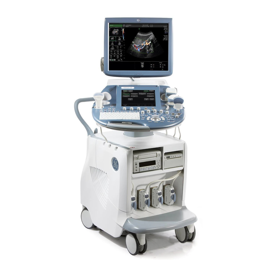
Sign In
Upload
Manuals
Brands
GE Manuals
Medical Equipment
Voluson E Series
GE Voluson E Series Manuals
Manuals and User Guides for GE Voluson E Series. We have
2
GE Voluson E Series manuals available for free PDF download: Service Manual
GE Voluson E Series Service Manual (356 pages)
Brand:
GE
| Category:
Ranges
| Size: 22.1 MB
Table of Contents
Table of Contents
3
Important Precautions
10
Legal Notes
18
Purpose of this Service Manual
19
Typical Users of the "Basic" Service Manual
19
Models Covered by this Manual
20
System History - Hardware and Software Versions
21
Purpose of Operator Manual(S)
22
Conventions Used in this Manual
23
Important Conventions
23
Standard Hazard Icons
23
Product Labels and Icons
24
Human Safety
27
Introduction
27
Safety Considerations
27
Mechanical Safety
28
Auxiliary Devices Safety
29
Electrical Safety
29
Dangerous Procedure Warnings
31
Labels Locations
31
Lockout/Tagout (LOTO) Requirements
32
Returning/Shipping System, Probes and Repair Parts
32
Compliance
33
Electrostatic Discharge (ESD) Prevention
33
EMC, EMI and ESD
33
What Is EMC
33
Contact Information
34
Customer Assistance
34
System Manufacturer
35
Chapter 2 - Site Preparation
37
General Requirements
38
Environmental Requirements
38
Electrical Requirements
38
EMI Limitations
39
Environmental Requirements for Probes
40
Time and Manpower Requirements
40
System Specifications
41
Facility Needs
42
Purchaser Responsibilities
42
Required Facility Needs
43
Desirable Features
44
Network Setup Requirements
44
Setup Reminders
46
Average Installation Time
46
Installation Warnings
46
Safety Reminders
48
Receiving and Unpacking the System
49
Preparing for Setup
51
Verify Customer Order
51
EMI Protection
52
Completing the Setup
53
Power on / Boot up
53
Power off / Shutdown
56
Probe Connection
57
Connection of Auxiliary Devices
58
Connecting the LCD Monitor
59
Connecting the OLED Monitor
60
Connecting the Black & White Printer
61
Connecting the Color Printer
63
Connecting the Network Color Laser Printer
65
Connecting the Deskjet Color Printer
68
Connecting the Cellular Modem
70
Connecting the Wireless Network Adapter
72
Connecting a Secondary "Patient" Monitor
73
Connecting the Footswitch
75
Connecting the Barcode Scanner
76
Connecting the ECG-Preamplifier
77
Connecting an USB Flash Memory Stick
78
Connecting an External USB Hard Disk
78
General Remarks When Using External USB-Devices
79
Printer Installation
80
Installing the Digital Black & White Printer
80
Installing the Digital Color Printer
80
Installing the Deskjet Color Printer Directly Via an USB-Cable
80
Printer Installation Manually
81
Adjustment of Printer Settings
82
Remote Control Selection
85
System Configuration
86
Setup
86
How to Enter Date and Time
88
How to Enter Clinic Name
88
How to Change Language And/Or EUM Language
88
How to Change Video Norm
89
How to Change Ext. Monitor Output Settings
89
How to Adjust Function of the Footswitch
89
How to Change the Keyboard Layout
89
How to Configure Insite
89
How to Execute Additional Software Installation (ASI)
89
How to Activate User Login Authentication
90
How to Perform Full Disk Encryption
90
How to Protect the System by Whitelisting
92
On-Board Optional Peripherals
93
External I/O Connectors
94
External I/O Pin Outs
96
Video Specification
98
External Cables - Maximum Lengths
98
Available Probes
98
Software/Option Configuration
98
Connectivity Setup
99
Connectivity Introduction
99
Network Configuration
101
TCP/IP Configuration
102
Wireless Network Configuration
103
How to Setup the Cellular Modem
108
How to Setup E-Mail
110
How to Setup E-Mail to MMS Service
111
How to Enter Patient's Email Address and Phone Number in the PID Screen
112
Map Network Drive
113
Insite Configuration
114
Connectivity Setup Worksheet
117
Paperwork
119
Product Locater Installation Card
119
User Manual(S)
119
Required Equipments
122
General Procedure
122
Power on / Boot up
123
Power off / Shutdown
124
System Features
125
Functional Checks
127
Patient Archive (Image Management)
128
Erasing DVD/CD
129
Backup and Restore Database, Preset Configurations and Images
130
Save Small Backup (Scan Settings)
131
Load Small Backup (Scan Settings)
132
Save Full System Configuration (Full Backup)
135
Load Full System Configuration (Full Backup)
137
Delete Full System Configuration (Full Backup)
139
Archiving Images
140
Software Configuration Checks
143
Setup
143
Peripheral Checks
144
ECG Check out
144
Mechanical Function Checks
145
Control Console Positioning
145
Brakes and Direction (Swivel) Locks
145
Site Log
146
General Information
148
Description of Operating Modes
152
Block Diagram Voluson E-Series
155
Data Flow Control Description
156
Description of Software Options
158
Description of Hardware Options
167
Data Location
168
Frontend Processor
169
RTF - Probe Control Board
170
RSE - Pencil Probe Board (Optional)
170
RFM - (RF-Interface & Beamformer) FE Mainboard
170
RSX - (Beamformer Receiver/Transmitter) Extension Board
170
Backend Processor
171
PC-Motherboard
172
Hard Disk Drive (HDD)
172
Graphic Card
172
RTV - Video Management Board
172
RTB - Distribution Board Bottom
172
Internal I/O
173
Internal I/O Voluson E-Series (BT15): ADVANTECH + Rtt/Rth6X
174
Internal I/O Voluson E-Series (BT15 / BT16): ADVANTECH + RTH50
175
Internal I/O Voluson E-Series (BT15): KONTRON + Rtt/Rth6X
176
Internal I/O Voluson E-Series (BT15 / BT16): KONTRON + RTH50
177
Internal I/O Voluson E-Series (BT17): ADVANTECH Micro-ATX
178
Internal I/O Voluson E-Series (BT18): ADVANTECH Micro-ATX
179
Internal I/O Voluson E-Series (BT18): KONTRON Micro-ATX
180
Control Console (User Interface)
181
RTH - Distribution Board USB-Hub
182
RTT - Distribution Board Top
182
Control Console (UI)
183
Monitor
185
External I/O
186
Peripherals
188
Recording Tools
188
Printers
188
DVD Drive
188
ECG-Preamplifier (man - Optional)
189
Wireless Network Adapter
189
Footswitch
189
Cellular Modem
189
Power Distribution
190
RSP - Power Supply Module
190
Mechanical Descriptions
191
Physical Dimensions
191
LCD Monitor
192
Control Console Positioning
192
Air Flow Control
193
Air Flow Distribution
193
Service Platform
194
Introduction
194
Service Platform - Access and Security
194
Common Service Desktop (CSD)
195
Service Page
196
Introduction
196
Service Page - Access and Security
196
Boot Screen Functions
199
Voluson
199
GE-Service
199
Rollback
199
Memtest (Memory Check)
200
Regulatory
202
LCD Monitor Adjustment
202
Preparing for Transport
203
Loading the Default Monitor Settings
203
Monitor Test
203
Control Console Positioning
204
Translation/Rotation Adjustment
204
Height Adjustment (Elevation)
205
Modification of Keyboard Layout
205
Collect Vital System Information
208
Shortcuts List
210
Request for Service (RFS)
211
Check Point Voltages
213
User Interface - Status Leds
213
Power Supply (RSP) Status Leds
213
Boot up Diagnostic Status Leds
214
Screen Captures and Logs
215
Capturing a Screen
215
Export Log's and System Data
216
Remote Access to the Service Platform
218
General
218
How the Customer Enables/Disables Disruptive Mode and VCO
219
Common Service Desktop (CSD)
220
Error Logs
220
Diagnostics
221
Image Quality
221
Calibration
221
Configuration
221
Utilities
222
Replacement
223
How to Use the Auto Tester Program
224
Limitation of the Auto Tester
225
Troubleshooting Trees, Instructions and Tech Tips
226
System Does Not Boot up
227
Noise Disturbs the Image
228
Trackball Malfunction
231
Printer Malfunction
232
Monitor Troubleshooting
233
DVD/CD-Drive Tests
234
Network Troubleshooting
237
Activate Windows - Network Connectivity Issues
238
Tech Tips
239
Chapter 8 - Replacement Procedures
241
Returning/Shipping System, Probes and Repair Parts
242
System Software - Installation/Upgrade Procedure
243
Before the Installation/Upgrade Procedure
244
System Software - Installation Procedure (FMI from DVD)
246
Software Update Package - Download/Installation Procedure
250
Software and Functional Checks after Installation/Upgrade Procedure
254
Image Settings Only - Loading Procedure
255
Full Backup (Full System Configuration) - Loading Procedure
255
Image Archive - Loading Procedure
255
Replacement or Activation of Options
256
How to Activate Options by Means of a "Demo Key" or a "Permanent Key
256
Replacement of Covers
257
Replacement of the Footrest Cover & Wheel Axis Cover
257
Replacement of the Front Frame
258
Replacement of the Air Filter Cover
259
Replacement of the Cable Holder
262
Cable Holder - Replacement Procedure
262
Replacement of the Probe Holder (Kit)
262
Probe Holder (Kit) - Replacement Procedure
262
Replacement of the Probe Holder for Endocavity Probes
263
Probe Holder (Endocavity) - Replacement Procedure
263
Replacement of the Trackball Ring
263
Trackball Ring - Replacement Procedure
263
Replacement of Key Caps (by Special Native Language Keys)
264
Key Caps - Removal Procedure
264
Key Caps - Installation Procedure
264
Replacement of the Caps for Encoders And/Or Joycoders
265
Caps for Encoders And/Or Joycoders - Replacement Procedure
265
Replacement of the Caps for Hardkeys
266
Replacement of Circle Key Caps Only
266
Replacement of Fuses at Power Supply Module (RSP)
267
Fuses at Power Supply Module (RSP) - Replacement Procedure
267
Replacing Optional Peripherals / How to Mount Peripherals at a Later Date
268
Mounting/Replacing a Secondary "Patient" Monitor
269
List of Abbreviations
272
Parts List Groups
273
Housing - Mechanical Hardware Parts & Covers
274
User Interface
279
Monitor + Monitor Replacement Parts
287
Main Power Modules
290
Main Board Module
290
Frontend (US-Part) Components
291
Backend (PC-Part) Components
294
Options and Upgrades
298
Miscellaneous Cables
300
Optional Peripherals and Accessories
307
Printers
307
Drives and Additional Devices
309
Optional Equipment
312
System Manuals
314
System Manuals for EC300
314
System Manuals for EC310
315
System Manuals for EC320
316
System Manuals for EC330
317
Probes
319
Probes - Curved Array Probes
319
Probes - Linear Array Probes
321
Probes - Phased Array Probes
322
Real-Time 4D Volume Probes
323
CW-Doppler - Pencil Probes
326
Biopsy Needle Guides
327
Why Do Maintenance
332
Periodic Maintenance Inspections
332
Keeping Records
332
Quality Assurance
332
Maintenance Task Schedule
332
How Often Should Care and Maintenance Tasks be Performed
332
Tools Required
334
Special Tools, Supplies and Equipment Used for Maintenance
334
System Maintenance
335
Preliminary Checks
335
Functional Checks
335
Physical Inspection
337
Cleaning
337
Probe Maintenance
338
Using a Phantom
339
Electrical Safety Tests
340
Safety Test Overview
340
Leakage Current Limits
341
Outlet Test - Wiring Arrangement - USA & Canada
342
Grounding Continuity
343
Chassis Leakage Current Test
344
Isolated Patient Lead (Source) Leakage-Lead to Ground
346
Isolated Patient Lead (Source) Leakage-Lead to Lead
347
Isolated Patient Lead (Sink) Leakage-Isolation Test
348
Probe (Source) Leakage Current Test
349
When There's too Much Leakage Current
353
AC/DC Fails
353
Chassis Fails
353
Probe Fails
353
Peripheral Fails
353
New Voluson E-Series System
353
ECG Fails
353
Ultrasound Equipment Quality Check
354
Advertisement
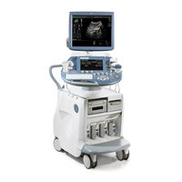
GE Voluson E Series Service Manual (366 pages)
Brand:
GE
| Category:
Medical Equipment
| Size: 22.66 MB
Table of Contents
Revision History
3
Table of Contents
3
Chapter 1 Introduction
9
Important Precautions
10
Legal Notes
18
Purpose of this Service Manual
19
Typical Users of the "Basic" Service Manual
19
Models Covered by this Manual
20
System History - Hardware and Software Versions
21
Purpose of Operator Manual(S)
22
Important Conventions
23
Conventions Used in this Manual
23
Standard Hazard Icons
23
Product Labels and Icons
24
Safety Considerations
27
Introduction
27
Human Safety
27
Mechanical Safety
28
Electrical Safety
29
Auxiliary Devices Safety
29
Labels Locations
31
Dangerous Procedure Warnings
31
Lockout/Tagout (LOTO) Requirements
32
Returning/Shipping System, Probes and Repair Parts
32
EMC, EMI and ESD
33
What Is EMC
33
Compliance
33
Electrostatic Discharge (ESD) Prevention
33
Customer Assistance
34
Contact Information
34
System Manufacturer
35
Chapter 2 - Site Preparation
37
General Requirements
38
Environmental Requirements
38
Electrical Requirements
38
EMI Limitations
39
Environmental Requirements for Probes
40
Time and Manpower Requirements
40
System Specifications
41
Facility Needs
42
Purchaser Responsibilities
42
Required Facility Needs
43
Desirable Features
44
Network Setup Requirements
44
Chapter 3 Setup Instructions
45
Setup Reminders
46
Average Installation Time
46
Installation Warnings
46
Safety Reminders
48
Receiving and Unpacking the System
49
Preparing for Setup
51
Verify Customer Order
51
EMI Protection
52
Connection of Auxiliary Devices
53
Connecting the LCD Monitor
54
Connecting the Black & White Printer
55
Connecting the Color Printer
57
Connecting the Deskjet Color Printer
59
Connecting the Network Color Laser Printer
61
Connecting the DVD Recorder
63
Connecting the USB Video Recorder
69
Connecting the Wireless Network Adapter
73
Connecting the VGA Image (Video) Resizer
74
Connecting a Secondary "Patient" Monitor
76
Connecting the Footswitch
79
Connecting the ECG-Preamplifier
80
Connecting an USB Flash Memory Stick
81
Connecting an External USB Hard Disk
81
General Remarks and Hints When Using External USB-Devices
82
Completing the Setup
83
Power on / Boot up
83
Power off / Shutdown
86
Probe Connection
87
Printer Installation
88
Installing the Digital Black & White Printer
88
Installing the Digital Color Printer
88
Installing the Deskjet Color Printer Directly Via an USB-Cable
88
Installing the Network Color Laser Printer
89
Printer Installation Manually
94
Adjustment of Printer Settings
95
Remote Control Selection
101
System Configuration
102
System Setup
102
Measure Setup
105
On-Board Optional Peripherals
106
External I/O Connectors
108
External I/O Pin Outs
109
Video Specification
110
External Cables - Maximum Lengths
110
Available Probes
110
Connectivity Setup
111
Connectivity Introduction
111
Software/Option Configuration
111
Network Configuration
113
TCP/IP Configuration
114
Setup Instructions 3.13.2 Wireless Network Configuration
115
Wireless Network Configuration
115
Adding a WLAN Profile
116
Refreshing a WLAN Network
116
Setting a WLAN Network as Non-Preferable
116
Customizing an Existing WLAN Profile
117
Removing a WLAN Profile
117
Available WLAN Channels
118
Monitoring the WLAN
118
Repairing the WLAN
119
WLAN Diagnostic
119
Map Network Drive
120
Insite Exc Configuration
121
Connectivity Setup Worksheet
124
Paperwork
126
Product Locater Installation Card
126
User Manual(S)
126
Chapter 4 - Functional Checks
128
General Procedure
128
Power on / Boot up
129
Power off / Shutdown
130
System Features
131
Required Equipments
128
Functional Checks
134
Mode (B-Mode)
135
Additional (Optional) Operating Modes
137
M-Mode
139
Spectral Doppler Mode
140
Color Doppler Mode
141
Volume Mode
143
Using Cine
146
Generic Measurements
148
Calculations
151
Probe/Connectors Usage
152
Patient Archive (Image Management)
153
Erasing DVD/CD
154
Backup and Restore Database, Preset Configurations and Images
155
Save Small Backup (Scan Settings)
156
Load Small Backup (Scan Settings)
157
Save Full System Configuration (Full Backup)
160
Load Full System Configuration (Full Backup)
162
Delete Full System Configuration (Full Backup)
164
Archiving Images
165
Software Configuration Checks
168
System Setup
168
Measure Setup
168
Peripheral Checks
169
ECG Check out
169
Mechanical Function Checks
170
Control Console Positioning
170
Brakes and Direction (Swivel) Locks
170
Site Log
171
Chapter 5 - Components and Functions (Theory)
174
General Information
174
Description of Operating Modes
178
Block Diagram Voluson E-Series
181
Data Flow Control Description
182
Description of Software Options
184
Description of Hardware Options
190
Data Location
191
Frontend Processor
192
RTF - Probe Control Board
193
RSE - Pencil Probe Board (Optional)
193
RFM - (RF-Interface & Beamformer) FE Mainboard
193
RSX - (Beamformer Receiver/Transmitter) Extension Board
193
Backend Processor
194
PC-Motherboard
195
Hard Disk Drive (HDD)
195
Graphic Card
195
RTV - Video Management Board
195
RTB - Distribution Board Bottom
195
Internal I/O
196
Internal I/O Voluson E-Series: ADVANTECH Micro ATX
197
Internal I/O Voluson E-Series: DFI Micro ATX
198
Control Console (User Interface)
199
RTH - Distribution Board USB-Hub
200
RTT - Distribution Board Top
200
Control Console (UI)
201
Monitor
203
External I/O
204
Peripherals
205
Recording Tools
205
Printers
205
DVD Drive
205
ECG-Preamplifier (man - Optional)
205
Wireless Network Adapter
206
Footswitch
206
Power Distribution
207
RSP - Power Supply Module
207
Mechanical Descriptions
208
Chapter 7 Diagnostics/Troubleshooting
227
Collect Vital System Information
228
Request for Service (RFS)
231
Check Point Voltages
233
Screen Captures and Logs
234
Remote Access to the Service Platform
237
How to Use the Auto Tester Program
243
Minimum Configuration to Boot/Scan
245
Diagnostics/Troubleshooting 7.9 Troubleshooting Trees, Instructions and Tech Tips
246
System Does Not Boot up
247
Noise Disturbs the Image
248
Trackball - Malfunction
251
Printer Malfunction
252
Monitor Troubleshooting
253
DVD/CD-Drive Tests
254
Network Troubleshooting
256
Tech Tips
257
Replacement Procedures Content in this Chapter
260
System Software - Installation/Upgrade Procedure
261
Software and Functional Checks after Installation/Upgrade Procedure
271
Full Backup (Full System Configuration) - Loading Procedure
272
Image Archive - Loading Procedure
272
Image Settings Only - Loading Procedure
272
Replacement or Activation of Options
273
Replacement of Covers
275
Replacement of the Cable Holder
277
Replacement of the Probe Holder (Kit)
278
Replacement of the Probe Holder for Endocavity Probes
279
Replacement of the Trackball Ring
279
Replacement of Key Caps (by Special Native Language Keys)
280
Replacement of the Caps for TGC Sliders And/Or Rotation Digipots
281
Replacement of the Caps for Hardkeys
282
Replacement of Fuses at Power Supply Module (RSP)
283
Replacing Optional Peripherals / How to Mount Peripherals at a Later Date
284
Chapter 9 Renewal Parts
289
List of Abbreviations
290
Housing - Mechanical Hardware Parts & Covers
292
User Interface
296
Monitor + Monitor Replacement Parts
305
Main Board Module
307
Options and Upgrades
312
Miscellaneous Cables
314
Optional Peripherals and Accessories
321
System Manuals
328
Probes
329
Biopsy Needle Guides
337
Chapter 10
342
Why Do Maintenance
342
Maintenance Task Schedule
342
Tools Required
344
System Maintenance
345
Using a Phantom
349
Electrical Safety Tests
350
When There's too Much Leakage Current
362
Ultrasound Equipment Quality Check
363
Advertisement
Related Products
GE Voluson i
GE Voluson e
GE Voluson E10
GE Voluson E8 Expert
GE Voluson E8 Expert Limited Edition
GE Voluson Swift
GE Voluson Swift+
GE Vscan Extend
GE Vivid q N
GE Vital Signs enFlow
GE Categories
Refrigerator
Ranges
Microwave Oven
Air Conditioner
Dishwasher
More GE Manuals
Login
Sign In
OR
Sign in with Facebook
Sign in with Google
Upload manual
Upload from disk
Upload from URL