Sign In
Upload
Manuals
Brands
AEMC Manuals
Measuring Instruments
PowerPad 8335
AEMC PowerPad 8335 Manuals
Manuals and User Guides for AEMC PowerPad 8335. We have
4
AEMC PowerPad 8335 manuals available for free PDF download: User Manual, Quick Start User Manual, Application Notes
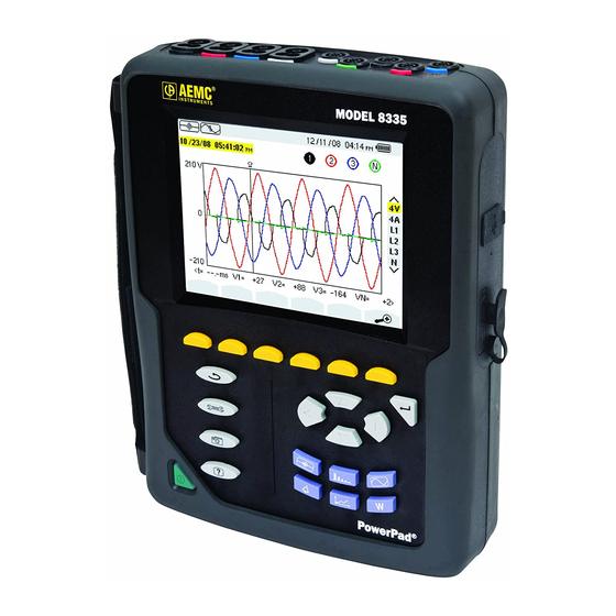
AEMC PowerPad 8335 User Manual (136 pages)
3-PHASE POWER QUALITY ANALYZER
Brand:
AEMC
| Category:
Measuring Instruments
| Size: 6 MB
Table of Contents
Table of Contents
4
1 Introduction
9
International Electrical Symbols
10
Definition of Measurement Categories
10
Receiving Your Shipment
11
Ordering Information
11
Accessories and Replacement Parts
12
2 Product Features
13
Description
13
Key Features
14
Control Functions
15
Display
16
Button Functions
18
3 Specifications
20
Reference Conditions
20
Electrical Specifications
21
Voltage Inputs
21
Current Inputs
21
Accuracy Specifications (Excluding Current Probes)
22
Current Probe Accuracy
30
Current Probes and Sensors
31
Three-Phase 5A Adapter Box (3-Channel Use Only)
33
Power Supply
34
Mechanical Specifications
35
Environmental Specifications
35
Safety Specifications
36
4 Operation
37
Getting Started
37
Lead Connections
38
Instrument Configuration (Set-Up Mode)
39
Date/Time
40
Ca Shop for AEMC Products Online At: Display
41
Contrast/Brightness
41
Colors
41
Calculation Methods
42
Connection
43
Sensors and Ratios
44
Voltage Ratios
45
Transient Mode Configuration
46
Current Thresholds
46
Voltage Thresholds
47
Trend Recording Mode Configuration
48
Alarm Mode Configuration
50
Erasing Memory
51
5 Display Modes
52
Waveform Capture Mode
52
Transient Mode
52
Programming and Starting a Search
53
Stopping a Search
54
Displaying a Transient
54
Deleting a Transient
55
Inrush Current Mode
56
Programming a Capture
56
Starting a Capture
57
Manually Stopping a Capture
57
Displaying the Parameters of a Capture
58
True RMS Current and Voltage
59
RMS Display Screen (3A)
59
RMS Display Screen (L1)
60
Instantaneous Inrush Current
60
PEAK Display Screen (4A)
60
PEAK Display Screen (A1)
61
Harmonics Mode
62
Phase-To-Neutral Voltage
62
Phase-To-Neutral Harmonics Display Screen (3L)
63
Phase Voltage Harmonics Display Screen (L1)
63
Current
64
Current Harmonics Display Screen (3L)
64
Current Harmonics Display Screen (L1)
65
Apparent Power
66
Apparent Power Harmonics Display Screen (3L)
66
Apparent Power Harmonics Display Screen (L1)
67
Phase-To-Phase Voltage
68
Phase-To-Phase Voltage Harmonics Display (3L)
68
Phase-To-Phase Voltage Display Screen (L1)
69
Harmonic Analysis in Expert Mode
70
Waveform Mode
71
RMS Measurement
71
RMS Display Screen (3U)
72
RMS Display Screen (4V)
73
RMS Display Screen (4A)
73
RMS Display Screen (Neutral)
74
THD Measurement of Total Harmonic Distortion
75
THD Display Screen (3U)
75
THD Display Screen (3V)
76
THD Display Screen (3A)
76
Measurement of the Peak Factor (CF)
77
CF Display Screen (3U)
77
CF Display Screen (3V)
78
CF Display Screen (3A)
78
Measurement of Min, Max, Average, Voltage and Current Values
79
Simultaneous Display
80
Display of Fresnel Diagram
82
Alarm Mode
83
Programming an Alarm
83
Starting an Alarm
84
Manually Stopping an Alarm
84
Displaying an Alarm Log
85
Deleting an Alarm Log
85
Trend Mode
86
Programming and Starting a Recording
86
Manually Stopping a Recording
87
Displaying the Recording List
87
Deleting a Recording
88
Power and Energy Mode
88
Power Quality Analyzer Model
88
Starting and Stopping Energy Measurements
89
Resetting the Energy Measurement
89
Snapshot Mode
90
Opening a Previously Saved Snapshot
90
Deleting a Snapshot
91
Help
91
6 Dataview ® Software
92
Installing Dataview
92
Connecting the Powerpad ® to Your Computer
96
Opening the Control Panel
96
Common Functions
98
Configuring the Instrument
98
Setup
99
Instrument Display
100
Alarm Conditions Configuration
101
Recordings Configuration
103
Transients
104
Inrush
105
Monitoring
106
Running the Test
107
Real-Time Windows
107
Waveform and Harmonic Graph
107
Power/Energy
108
Trend
108
Downloading Data
109
Saving Real-Time Measurements
111
7 Maintenance
113
Battery Indicator
113
Recharging the Battery
114
Changing the Battery
114
Cleaning
114
Mathematical Formulas for Various Parameters
115
RMS Values of Half-Cycle Voltage and Current
115
Appendix A
115
Minimum and Maximum Half-Cycle RMS Values
116
Short-Term Flicker - 10 Minute (Excluding Neutral)
116
Peak Values
116
Peak Factors (Excluding Neutral - over 250Ms)
117
RMS Values
117
Voltage and Current Unbalance
118
Harmonic Calculations
118
Harmonic Distortions
119
K Factor
120
Sequence Harmonics
120
Powers
121
Power Ratios
121
Energies (Excluding Neutral)
122
Hysteresis
124
Minimum Scale Values for Waveforms and Minimum RMS Values
125
Four-Quadrant Diagram
126
Mechanism for Triggering Transient Sensors
126
Capture Conditions in Inrush Current Mode
127
Glossary of Terms
128
Appendix B
128
Symbols & Abbreviations
130
Repair and Calibration
133
Technical and Sales Assistance
133
Limited Warranty
134
Warranty Repairs
134
Advertisement
AEMC PowerPad 8335 User Manual (112 pages)
PowerPad 3-PHASE POWER QUALITY ANALYZER
Brand:
AEMC
| Category:
Measuring Instruments
| Size: 5 MB
Table of Contents
Table of Contents
4
1 Introduction
8
International Electrical Symbols
9
Definition of Measurement Categories
9
Receiving Your Shipment
10
Ordering Information
10
Accessories and Replacement Parts
11
2 Product Features
12
Description
12
Key Features
13
Control Functions
14
Display
15
Button Functions
17
3 Specifications
18
Reference Conditions
18
Electrical Specifications
18
Voltage Inputs
19
Current Inputs
19
Accuracy Specifications
19
Current Probe Accuracy
23
Current Probes and Sensors
24
Power Supply
25
Mechanical Specifications
26
Environmental Specifications
26
Safety Specifications
26
Three-Phase 5A Adapter Box (3-Channel Use Only)
27
Connecting to Secondary Current Transformer (CT)
28
Specifications
28
4 Operation
30
Getting Started
30
Lead Connections
31
Instrument Configuration (Set-Up Mode)
32
Electrical Hookup (Electrical Network)
33
Setting the Parameters for Current Probes
34
Setting the Parameters for a Recording (Trend Mode)
35
Setting the Parameters for Alarms
38
Erasing Memory
39
5 Display Modes
40
Waveform Mode
40
RMS Measurement
40
THD Measurement of Total Harmonic Distortion
43
Measurement of the Peak Factor (CF)
46
Measurement of Min, Max, Average, Voltage and Current
48
Simultaneous Display
49
Display of Fresnel Diagram
50
Power and Energy Mode
51
Starting and Stopping Energy Measurements
52
Resetting the Measurement to Zero
52
6 Recording Modes
53
Waveform Capture Mode
53
Transient Mode
53
Inrush Current Mode
57
Harmonics Mode
61
Single Phase Voltage Analysis
61
Single Phase Current Analysis
62
Harmonic Analysis in Expert Mode
63
Alarm Mode
64
Programming an Alarm
64
Starting an Alarm
65
Manually Stopping an Alarm
65
Displaying an Alarm Log
65
Deleting an Alarm Log
66
Trend Mode
67
Programming and Starting a Recording
67
Manually Stopping a Recording
68
Displaying the Recording List
68
Deleting a Recording
69
Snapshot Mode
69
Opening a Previously Saved Snapshot
69
Deleting a Snapshot
70
Help
70
7 Dataview ® Software
71
Features
71
Installing Dataview
71
Connecting the Powerpad to Your Computer
75
Opening the Control Panel
75
Common Functions
77
Configuring the Instrument
77
Setup
78
Instrument Display
79
Alarm Conditions Configuration
80
Recordings Configuration
82
Transients
83
Inrush
84
Monitoring
85
Running the Test
86
Real-Time Windows
86
Waveform and Harmonic Graph
86
Power/Energy
87
Trend
87
Downloading Data
88
Saving Real-Time Measurements
90
8 Maintenance
92
Battery Indicator
92
Recharging the Battery
93
Changing the Battery
93
Cleaning
93
Appendix A: Mathematical Formulas
94
Half-Period Voltage and Current RMS Values
94
MIN / MAX Values for Voltage and Current
94
Peak Values for Voltage and Current
95
Peak Factors for Current and Voltage
95
Sec RMS Values for Voltage and Current
96
Voltage and Current Unbalance
96
THD Calculation (no Neutral)
96
Calculation of Harmonic Bins
97
Distortion Factor Calculation (DF)
98
K Factor
98
Different Power Levels 1 Sec (no Neutral)
99
Ratios
99
Various Types of Energy (no Neutral)
100
Hysteresis
101
Minimum Scale Values for Waveforms and Minimum RMS Values
102
Diagram of the 4 Quadrants
103
Mechanism for Triggering Transient Sensors
103
Sensor Conditions in Ringing Current Mode
104
Appendix B: Glossary of Terms
105
Repair and Calibration
107
Technical and Sales Assistance
107
Limited Warranty
108
Warranty Repairs
108
AEMC PowerPad 8335 Quick Start User Manual (13 pages)
Brand:
AEMC
| Category:
Measuring Instruments
| Size: 0 MB
Table of Contents
Statement of Compliance
2
Product Packaging
3
Charging the Battery
4
Button Functions
4
Control Features
5
Connection Terminals
5
Instrument Configuration
6
Getting Started
7
Installation of the Leads and Current Sensors
7
Installing Dataview
8
Repair and Calibration
9
Technical and Sales Assistance
9
Limited Warranty
10
Warranty Repairs
10
Advertisement
AEMC PowerPad 8335 Application Notes (6 pages)
Three-Phase Power Quality Analyzer
Brand:
AEMC
| Category:
Measuring Instruments
| Size: 1 MB
Advertisement
Related Products
AEMC PowerPad 8435
AEMC 8335 Power Pad
AEMC 8230
AEMC 8220
AEMC 8500
AEMC PowerPad 8436
AEMC 8345
AEMC 8336
AEMC powerpad 3945
AEMC PowerPad III 8336
AEMC Categories
Measuring Instruments
Test Equipment
Multimeter
Data Loggers
Thermometer
More AEMC Manuals
Login
Sign In
OR
Sign in with Facebook
Sign in with Google
Upload manual
Upload from disk
Upload from URL