AEMC 8335 User Manual
Powerpad 3-phase power quality analyzer
Hide thumbs
Also See for 8335:
- User manual (136 pages) ,
- Quick start user manual (13 pages) ,
- Application notes (6 pages)
Table of Contents

Related Manuals for AEMC 8335


Summary of Contents for AEMC 8335
- Page 1 8335 3-PHASE POWER QUALITY ANALYZER PowerPad ® IMPORTANT WARRANTY NOTE: By registering online or returning your warranty card within 30 days from the date of purchase, your warranty will be extended to 3 years E N G L I S H...
- Page 2 Statement of Compliance Chauvin Arnoux , Inc. d.b.a. AEMC Instruments ® ® certifies that this instrument has been calibrated using standards and instruments traceable to international standards. We guarantee that at the time of shipping your instrument has met its published specifications.
- Page 3 READ CAREFULLY BEFORE USING FOR THE FIRST TIME Your instrument is equipped with a NiMH battery. This technology offers several advantages: • Long battery charge life for a limited volume and weight. • Possibility of quickly recharging your battery. • Significantly reduced memory effect: you can recharge your battery even if it is not fully discharged.
-
Page 4: Table Of Contents
Table of Contents 1. INTRODUCTION ................6 International Electrical Symbols ............7 Definition of Measurement Categories ..........7 Receiving Your Shipment ..............8 Ordering Information ................8 1.4.1 Accessories and Replacement Parts ........9 2. PRODUCT FEATURES ..............10 Description ..................10 Key Features ..................11 Control Functions ................12 Display ....................13 Button Functions ................15 3. - Page 5 (Set-up mode) ........30 Instrument Configuration 4.3.1 Electrical Hookup (electrical network) ........31 4.3.2 Setting the Parameters for Current Probes......32 4.3.3 Setting the Parameters for a Recording (Trend Mode) ..33 4.3.4 Setting the Parameters for Alarms ........36 4.3.5 Erasing Memory ..............37 5. DISPLAY MODES ................38 Waveform Mode ................38 5.1.1 RMS Measurement ...............38...
- Page 6 6.4.3 Displaying the Recording List ..........66 6.4.4 Deleting a Recording ............67 Snapshot Mode .................67 6.5.1 Opening a Previously Saved Snapshot ........67 6.5.2 Deleting a Snapshot..............68 Help ....................68 7. DATAVIEW SOFTWARE ..............69 ® Features .....................69 Installing DataView ................69 ® Connecting the PowerPad to your Computer ........73 ®...
- Page 7 APPENDIX A: MATHEMATICAL FORMULAS .......... 92 Half-period Voltage and Current RMS Values ........92 MIN / MAX Values for Voltage and Current ........92 Peak Values for Voltage and Current ..........93 Peak Factors for Current and Voltage ..........93 1 sec RMS Values for Voltage and Current ........94 Voltage and Current Unbalance ............94 THD Calculation (no neutral)..............94 Calculation of Harmonic Bins .............95...
-
Page 8: Introduction
Comply with the limits of the accessory or sensor safety mechanisms. Do not keep hands close to unused terminals. • Certain current sensors cannot be inserted and removed from bare conductors under a dangerous voltage: consult the sensor’s manual and comply with handling instructions. Power Quality Analyzer Model 8335... -
Page 9: International Electrical Symbols
CAT III: Measurement category III corresponds to measurements on building installations. Example: measurement on distribution panels, cabling, etc. CAT IV: Measurement category IV corresponds to measurements taken at the source of low-voltage installations Example: metering and measurements on overvoltage protection devices. Power Quality Analyzer Model 8335... -
Page 10: Receiving Your Shipment
Model 8335 w/4 MN93-BK ..........Cat. #2136.21 ® Includes the PowerPad Model 8335, four MN93-BK (240A) probes, five 10 ft black voltage leads, ® five black alligator clips, twelve color-coded input ID markers, USB cable, NiMH battery, 110/240V power adapter with US power cord, DataView software, extra large classic tool bag, soft carrying ®... -
Page 11: Accessories And Replacement Parts
Model 8335 w/4 MN193-BK ........Cat. #2136.26 ® Includes the PowerPad Model 8335, set of four MN193-BK (6A/120A) probes, five 10 ft black ® voltage leads, five black alligator clips, twelve color-coded input ID markers, USB cable, NiMH battery, 110/240V power adapter with US power cord, DataView software, extra large classic tool ®... -
Page 12: Product Features
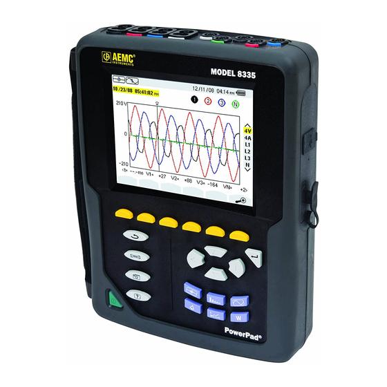
PRODUCT FEATURES 2.1 Description The easy-to-use, compact and shock-resistant PowerPad Model 8335 is a three- ® phase power quality analyzer equipped with four current probes and five voltage inputs. It is intended for technicians and engineers to measure and carry out diagnostic work and power quality work on one, two or three phase low voltage networks. -
Page 13: Key Features
Detection of transients and recording of associated waveforms. • Color-coded input tags to identify voltage and current inputs to local standards. • 2GB internal memory • DataView software included for downloading measurements, storage, ® and analysis and report generation. Power Quality Analyzer Model 8335... -
Page 14: Control Functions
ON / OFF button. Four (4) current inputs on the top of the instrument to enable the use of current sensors (MN, SR, AmpFlex , MiniFlex , and MR probes). ® ™ Power Quality Analyzer Model 8335... -
Page 15: Display
Measured RMS values associated with waveforms. Values of signals at an instant “t”, at the intersection of cursor and the waveforms. The cursor can be moved along the time scale by pressing the ◄ and ► buttons. Power Quality Analyzer Model 8335... - Page 16 Up/down key prompt PF... Display of PF, DPF and Tan. W... Active power. Recording mode Recording display and selection mode Validation prompt Shutdown function in progress prompt Display of energy consumed Display of energy generated Power Quality Analyzer Model 8335...
-
Page 17: Button Functions
• records measured and calculated vales (Urms, Vrms, Arms, etc.) Power / Energy: • display of power levels and the associated parameters (power factor, displacement and tangent) • energy monitoring • four quadrant measurement to discern produced/consumed active ener- gies and inductive/capacitive reactive energies Power Quality Analyzer Model 8335... -
Page 18: Specifications
15.36kHz samples/sec per channel @ 60Hz Waveforms: Displays voltages and currents Screen captures: 50 max Transients: Detection and recording of transients (up to 210) Inrush Current: Detection and recording of Inrush current (1 max) Memory: 2GB with date and time programming Alarm Function: 10,000 alarms max Power Quality Analyzer Model 8335... -
Page 19: Voltage Inputs
I ≥ 1000A Current TRMS 0.1A I < 1000A AmpFlex ® ±(0.5% + 1A) 6500A & MiniFlex ™ I ≥ 1000A 0.1A I < 1000A ±(1% + 1A) Direct Current (DC) 1200A I ≥ 1000A Power Quality Analyzer Model 8335... - Page 20 , Cat. III, providing that voltage between each of the terminals and ground does not exceed 1000V RMS. (2) Two phase (opposite phases) – same note as (1). (3) Limitation of the MR clamp. 1000 × 1414 × × × 2000 × 2828 6500 × 9190 Power Quality Analyzer Model 8335...
- Page 21 RMS and current modes are half-period values. NOTE: The uncertainties given for power and energy measurements are maximum for |Cos φ| = 1 or |Sin φ| = 1 and are typical for other phase displacement values. Power Quality Analyzer Model 8335...
- Page 22 ™ ∈ [26; 50] (Irms > Inom ÷ 10) Global Harmonic Rate ±(1% + 5cts) (THD or THD-F) 999.9% 0.1% rank ≤ 50 Distorsion Factor (DF or THD-R) ±(1% + 10cts) 999.9% 0.1% ≤ 50 Power Quality Analyzer Model 8335...
-
Page 23: Current Probe Accuracy
[300mA; 1A] ±(1.5°) 100A [1A; 120A] ±(0.7%) ±(0.7°) [5mA; 50mA] ±(1% + 0.1mA) ±(1.7°) MN193 [50mA; 500mA] ±(1%) ±(1°) [500mA; 6A] ±(0.7%) [5mA; 50mA] ±(1%) ±(1°) Adapter [50mA; 6A] ±(0.5%) ±(0°) N.S. = Not Specified Power Quality Analyzer Model 8335... -
Page 24: Current Probes And Sensors
NOTE: Currents < (Primary x 5) ÷ (Secondary x 1000) or <250mA on the 5A range and <0.2A on the 100A range will be displayed as zero with this probe. Power calculations will also be zeroed when the current is zeroed when the current is zeroed. Power Quality Analyzer Model 8335... -
Page 25: Power Supply
When the charger is connected, the battery starts to charge and the ON/OFF button will stay illuminated. Once the battery is charged, the instrument uses the current supplied by the power supply, without drawing from the battery. Power Quality Analyzer Model 8335... -
Page 26: Mechanical Specifications
The use of the MR193, MN93 and MN193 probes rate the “device + cur- rent probe” at 300V CAT IV or 600V CAT III. • The use of the 5A adapter rates the “device + current probe” at 150V CAT IV or 300V CAT III. Power Quality Analyzer Model 8335... -
Page 27: Three-Phase 5A Adapter Box (3-Channel Use Only)
This adapter is a three-phase adapter with three 5A inputs L1, L2, L3 and three AC voltage outputs. All circuits are independent and isolated between input and output. The outputs are equipped with connectors to mate with the PowerPad ® current channel inputs. Power Quality Analyzer Model 8335... -
Page 28: Connecting To Secondary Current Transformer (Ct)
Pollution Degree 2 per IEC 61010-1 Operating Temperature: 5° to 131°F (-15° to 55°C), 0 to 90% RH Storage Temperature: -40° to 185°F (-40° to 85°C), 0 to 90% RH Reference Conditions: 73°F (23°C) ±3K, 50 to 85% RH, 50/60Hz ±2Hz Power Quality Analyzer Model 8335... - Page 29 0.25% + 0.5mA Phase Error 0.5° 0.4° 0.33° Primary Voltage Loss: < 0.3V Permanent Overload: Temperature Influence: < 0.1% par 25K Frequency Influence 65Hz to 500Hz 500Hz to 1kHz 1kHz to 5kHz Error 0.1% 0.3% 0.5% Phase error 0.1° 0.2° 1° Power Quality Analyzer Model 8335...
-
Page 30: Operation
USB sockets can be used to connect the unit to any type of network. The following precautions for use must be complied with: • Do not connect any voltages exceeding 1000Vrms in relation to the ground/earth. • When connecting and disconnecting the batteries, check that measuring leads are disconnected. Power Quality Analyzer Model 8335... -
Page 31: Lead Connections
Location to plug in the voltage input color-coded ID markers Attach the color-coded input ID markers, that were shipped with the instrument, to items #1 and #4 above, to define the corresponding probe inputs and probe leads. Power Quality Analyzer Model 8335... -
Page 32: Instrument Configuration (Set-Up Mode)
Determines if harmonics are used or not used in calculations of reactive quantities (power and energy) - With harmonics: harmonics are taken into account when calculating reactive parameters. - Without harmonics: only the fundamental part is used for the calculation of reactive parameters Power Quality Analyzer Model 8335... -
Page 33: Electrical Hookup (Electrical Network)
• Highlight Electrical Hook-up using the ▲ and ▼ buttons, then press the button. Figure 4-3 • Choose the hookup type using the arrow buttons. • Press the button to apply the new hookup selection. Power Quality Analyzer Model 8335... -
Page 34: Setting The Parameters For Current Probes
Connect the current probes to the PowerPad before setting up the probe ® ratio. Use the same type of probe for each phase. • Highlight Current Probe with the ▲ and ▼ buttons, then press the button. Figure 4-4 Power Quality Analyzer Model 8335... -
Page 35: Setting The Parameters For A Recording (Trend Mode)
• Highlight Trend Mode with the ▲ and ▼ buttons, then press the button. The following screen will appear: If these options are not selected, all the harmonics (odd and even) will be recorded. Figure 4-5 Power Quality Analyzer Model 8335... - Page 36 Select the ? line you want to modify using the ▲ and ▼ buttons, then press the button to confirm. Next use the ▲ and ▼ buttons to scroll through the available choices (Uh, Vh, Ah, and VAh), then press Power Quality Analyzer Model 8335...
- Page 37 If in the Record Mode, and the display does not come ON, do not turn the instrument OFF. Supply power to the PowerPad with the power cord and ® the display will come back ON when any button (other than ON/OFF) is pressed. Power Quality Analyzer Model 8335...
-
Page 38: Setting The Parameters For Alarms
- Value 1, 2, 5 or 10%). • Activating the alarm (read item) or deactivating it (see next page). Power Quality Analyzer Model 8335... -
Page 39: Erasing Memory
WARNING: By choosing to delete all data, all detected alarms, screen snapshots, captured transient states and all recordings are deleted. To leave this screen without deleting anything, press the button. Power Quality Analyzer Model 8335... -
Page 40: Display Modes
: 3U, 3V, 3A, L1, L2 and L3 For RMS, : 3U, 4V, 4A, L1, L2, L3 and N The screen captures shown in this section are examples of those obtained with a 3-Phase 5-Wire connection. Power Quality Analyzer Model 8335... - Page 41 U3: instantaneous value of the line voltage between phases 3 and 1 (U31) 5.1.1.2 RMS Display Screen in 4V This screen displays the three phase voltages and the neutral relative to the earth of a 3-Phase system. Figure 5-2 Power Quality Analyzer Model 8335...
- Page 42 (expressed in milliseconds) A1: instantaneous value of the phase current of graph 1 A2: instantaneous value of the phase current of graph 2 A3: instantaneous value of phase current of graph 3 AN: instantaneous value of neutral Power Quality Analyzer Model 8335...
-
Page 43: Thd Measurement Of Total Harmonic Distortion
This sub-menu displays the waveforms over a period of the measured signals and the total harmonic distortion rates for voltage and current. 5.1.2.1 THD Display Screen in 3U This screen displays the waveforms of a period of the line voltages and the total harmonic distortion rates. Power Quality Analyzer Model 8335... - Page 44 U3: instantaneous value of the line voltage between phases 3 and 1 (U31) 5.1.2.2 THD Display Screen in 3V This screen displays the waveforms of a period of the phase voltages and the total harmonic distortion rates. Figure 5-6 Power Quality Analyzer Model 8335...
- Page 45 (expressed in milliseconds) A1: instantaneous value of the phase current of graph 1 A2: instantaneous value of the phase current of graph 2 A3: instantaneous value of phase current of graph 3 Power Quality Analyzer Model 8335...
-
Page 46: Measurement Of The Peak Factor (Cf)
U1: instantaneous value of the line voltage between phases 1 and 2 (U12) U2: instantaneous value of the line voltage between phases 2 and 3 (U23) U3: instantaneous value of the line voltage between phases 3 and 1 (U31) Power Quality Analyzer Model 8335... - Page 47 V2: instantaneous value of the phase voltage of graph 2 V3: instantaneous value of phase voltage of graph 3 5.1.3.3 CF Display Screen in 3A This screen displays the waveforms of a period of the currents and the peak fac- tors. Figure 5-10 Power Quality Analyzer Model 8335...
-
Page 48: Measurement Of Min, Max, Average, Voltage And Current
Minimum RMS value of the voltage or current from powering of the PowerPad or from ® the last time the button is pressed. PEAK+ Maximum peak value of the voltage or current PEAK- Minimum peak value of the voltage or current Power Quality Analyzer Model 8335... -
Page 49: Simultaneous Display
Short-term flicker (over 10 minutes) K factor - Oversizing of transformer relative to harmonics Note: L2 and L3 give information concerning simultaneous display of the current and of the voltage respectively for phases 2 and 3. Power Quality Analyzer Model 8335... -
Page 50: Display Of Fresnel Diagram
Unbalance of line voltages Note: L2 and L3 display the absolute value of the current and of the voltage at the fundamental frequency and the phase displacement of the voltage relative respec- tively to phases 2 and 3. Power Quality Analyzer Model 8335... -
Page 51: Power And Energy Mode
Resets the energy value to zero Stops the measurement Displacement factor Tangent Active energy generated Inductive reactive power Reactive energy consumed WARh - Inductive - Capacitive Apparent power (total if 3φ) Apparent energy consumed VARh Reactive energy Power Quality Analyzer Model 8335... -
Page 52: Starting And Stopping Energy Measurements
All energy meters will be stopped. 5.2.2 Resetting the Measurement to Zero To reset the measurement, press the icon’s yellow button to confirm. All energy values (consumed and generated) are reset. Power Quality Analyzer Model 8335... -
Page 53: Recording Modes
NOTE: When the Transient mode is selected, the display screen will depend on the following conditions: if … then … no record has been made the Detection Schedule screen is displayed transients have been recorded the Recording List screen is displayed Power Quality Analyzer Model 8335... - Page 54 To start programming a search between the start and end times which you have defined press the yellow button for the OK icon. • OK icon disappears and the icon appears instead. • When the start time is reached the message Search pending is dis- played. Power Quality Analyzer Model 8335...
- Page 55 Select the line of the transient to be displayed. The selected field appears in bold text. The screen displays the transients in the form of graphs. Power Quality Analyzer Model 8335...
- Page 56 Select the transient to be deleted using the ▲ and ▼ buttons, then press the symbol. To leave this screen without deleting, press any of the Mode buttons on the Pow- erPad ® To return to the Waveform Capture screen, press Power Quality Analyzer Model 8335...
-
Page 57: Inrush Current Mode
Current date and time Battery charge level Displays the parameters of the capture Programs the capture OK: confirms programming of a capture : deletes a capture (this icon is displayed if a capture has been made) Power Quality Analyzer Model 8335... - Page 58 OK icon will reappear in the same location. 6.1.2.4 Displaying the Parameters of a Capture To display the parameters of a capture, proceed as follows: Select the sub-menu by pressing the icon’s yellow button. The Capture Parameters screen is displayed. Power Quality Analyzer Model 8335...
- Page 59 Maximum instantaneous value of the start-up period (PEAK). • Start time and duration of engine start-up. A voltage must be present on the phase before the motor start-up for a stable and correct frequency control. Power Quality Analyzer Model 8335...
- Page 60 Note: Filters A1 and A3 display the record of the trend of the half-period true effec- tive value of the current over phases 1 and 3. The screen is identical to the one displayed for filter A2. Power Quality Analyzer Model 8335...
-
Page 61: Harmonics Mode
Harmonic order Percentage relative to the fundamental RMS value Phase angle in relation to the fundamental, according to the measure- ment type chosen (in this example V) with the variable function buttons just below the screen. Power Quality Analyzer Model 8335... -
Page 62: Single Phase Current Analysis
- Percentage in relation to the fundamental - RMS value and phase angle in relation to the fundamental component • MIN, MAX instantaneous values for the selected current harmonic MIN, MAX values are reset each time the cursor position is changed. Power Quality Analyzer Model 8335... -
Page 63: Harmonic Analysis In Expert Mode
• Column Two: Those inducing a zero sequence (triplens added into the neutral). • Column Three: Those inducing a positive sequence. Harmonic content is useful to evaluate the influence of harmonics that cause heat- ing of the neutral or on rotating machines. Power Quality Analyzer Model 8335... -
Page 64: Alarm Mode
To program/display alarms, they must first be configured (see § 4.3.4) Figure 6-11 Item Measurement Type Configures alarms Displays alarm log Programs an alarm Validates the programming of an alarm (after OK is selected, the icon appears) Manually stops an alarm that is in progress Power Quality Analyzer Model 8335... -
Page 65: Starting An Alarm
The log can contain a maximum of 14,336 alarms. The type of connection selected in the configuration mode does not affect the possibilities of alarm filter choice and monitored parameter. Users are responsible for these choices. Power Quality Analyzer Model 8335... -
Page 66: Deleting An Alarm Log
Press the icon’s yellow button Select the alarm to be deleted using the ▲ or ▼ button, then press the button to confirm deletion. To leave this screen without deleting any alarm, press the button. Power Quality Analyzer Model 8335... -
Page 67: Trend Mode
Using the same method as steps 1, 2 and 3, use the arrow buttons and the button to change the values for Stop, Period and Name. Press the OK icon’s yellow button to begin recording between your specified start and end times. The OK icon disappears and the icon appears. Power Quality Analyzer Model 8335... -
Page 68: Manually Stopping A Recording
OK icon will reappear in the same location. 6.4.3 Displaying the Recording List Press the icon’s yellow button to view the recording list. Figure 6-14 Item Function Recording name Memory usage Recording start time Recording end time Power Quality Analyzer Model 8335... -
Page 69: Deleting A Recording
• The small icon to the left of each snapshot (date and time) tells you what type of data was stored. Figure 6-15 Power Quality Analyzer Model 8335... -
Page 70: Deleting A Snapshot
To leave this screen without deleting any alarm, press the button. 6.5 Help Press this button to obtain help for the current display mode. To exit the Help mode, press the button once again. Power Quality Analyzer Model 8335... -
Page 71: Dataview ® Software
7.2 Installing DataView ® DO NOT CONNECT THE INSTRUMENT TO THE PC BEFORE INSTALLING THE SOFTWARE AND DRIVERS. Minimum Computer Requirements: • Windows 2000/XP/Vista ® • 2GB of RAM • 8GB of hard disk space (recommended) • CD-ROM drive Power Quality Analyzer Model 8335... - Page 72 ® recent version of Adobe Reader to the computer. Adobe Reader is ® ® required for viewing PDF documents supplied with DataView that are ® accessible from the Help menu. Power Quality Analyzer Model 8335...
- Page 73 .dmf or .emf files generated by DataView without having DataView ® ® software installed. • Software Updates - Links to the AEMC Software Update website to ® check for new software version releases. • Firmware Upgrades - Links to the AEMC Firmware Upgrade website ®...
- Page 74 If you connected your instrument to the computer before installing the software and drivers, you may need to use the Add/Remove Hardware utility to remove the instrument driver before repeating the process. Power Quality Analyzer Model 8335...
-
Page 75: Connecting The Powerpad To Your Computer
For detailed instructions and descriptions for any feature in a dialog box, click on the Help Button, or right-click on the feature you want infor- mation about. Power Quality Analyzer Model 8335... - Page 76 Window menu. If the battery charge is shown to be unknown, plug the PowerPad into AC ® Power. When it reaches 100% charge, the display should again be able to show the battery charge. Power Quality Analyzer Model 8335...
-
Page 77: Common Functions
Several of the functions are configured by typing the appropriate value in the field provided. Others are configured by clicking on the appropriate radio button or Icon, such as, selecting the current probe. To configure the instrument, go to Instrument > Configure or select Configura- tion from the Instrument Tree. Power Quality Analyzer Model 8335... -
Page 78: Setup
• Voltage Transformer Ratio: Sets the scale for voltage measurement in cases where measurements are on the secondary side of a transformer and the pri- mary value needs to be displayed. Power Quality Analyzer Model 8335... -
Page 79: Instrument Display
Figure 7-8 For detailed instructions and descriptions for any feature in a dialog box, click on the Help Button (lower right-side of the dialog box), or right- click on the feature you want information about. Power Quality Analyzer Model 8335... -
Page 80: Alarm Conditions Configuration
VPST: voltage short term flicker Vthd: voltage total harmonic distortion Vcf: voltage crest factor Uthd: voltage phase minus phase total Ucf: voltage phase minus phase harmonic distortion crest factor Athd: current total harmonic distortion Acf: current crest factor active power Power Quality Analyzer Model 8335... - Page 81 Example: Alarm threshold is 100 Volts or higher, hysteresis is 1%. When the volt- age goes up to 100V, the alarm condition starts. When it goes back down to 99V, the alarm condition stops. NOTE: You can configure alarms, recordings, inrush, and transient searches while testing is in progress. Power Quality Analyzer Model 8335...
-
Page 82: Recordings Configuration
Choose a starting and ending time to assign a time period for the record- ing to run. Enter a name for the recording (up to 8 characters), if desired. Choose an “Averaging Period” for the recording, which sets how often the recording updates while it is running. Power Quality Analyzer Model 8335... -
Page 83: Transients
Select the percent deviation for voltage and current transients. The choices available from the drop-down menu are 1, 2, 5, 10, 20, 50 and 100% of the full scale range of measurement. Select the maximum number of transients to capture (from 1 to 210). Power Quality Analyzer Model 8335... -
Page 84: Inrush
Assign a Current Threshold in Amps, to trigger the inrush recording. Select the Channel to run the Inrush search on. The search can be performed on one of the three current channels (A1, A2, A3) or all three (3A). Select a Hysteresis percentage. Power Quality Analyzer Model 8335... -
Page 85: Monitoring
The frequency is not asked for, since it will be asked for when the test result is downloaded. Follow the instructions in the dialog box to set up and run this special test. Press the Help button for further instructions. Power Quality Analyzer Model 8335... -
Page 86: Running The Test
Print the screen selected. • Save the data by choosing either Create DataView Report to view the data in a DataView report or Create Spreadsheet to view in a Spreadsheet program ® (e.g. Microsoft Excel). ® Power Quality Analyzer Model 8335... -
Page 87: Power/Energy
The data for all available phases are downloaded to a database or spread- sheet, not just what is shown on the screen. 7.7.3 Trend Figure 7-16 Power Quality Analyzer Model 8335... -
Page 88: Downloading Data
(.csv file) which can then be viewed, modified and saved. “View” opens up a window with a graph of the data where the user can select to “Print”, “Create DataView Report”, and “Create Spread- sheet”. Power Quality Analyzer Model 8335... - Page 89 These controls are available in every graph from recorded data. There is also a checkbox, “View As List”, which can be used to show the value of every datapoint. Power Quality Analyzer Model 8335...
-
Page 90: Saving Real-Time Measurements
When the “Rec to PC” option is unchecked the file can be opened by select- ing “Yes” from the View Saved File dialog box. To edit the Session Properties, return to the Power Analyzer Control Panel and select File > Edit Session Properties. Power Quality Analyzer Model 8335... - Page 91 In addition to the pre-designed report templates, DataView allows you ® to totally configure reports to your needs. Refer to the DataView HELP ® file on “Templates” to learn more about templates. Power Quality Analyzer Model 8335...
-
Page 92: Maintenance
CHAPTER 8 MAINTENANCE Use only factory specified replacement parts. AEMC will not be held responsible ® for any accident, incident, or malfunction following a repair done other than by its service center or by an approved repair center. Before first use, charge and discharge the instrument one or two cycles to ensure the proper level display of the battery indicator. -
Page 93: Recharging The Battery
Use a soft cloth, lightly dampened with soapy water • Wipe with a damp cloth and then dry with a dry cloth • Do not splash water directly on the clamp • Do not use alcohol, solvents or hydrocarbons Power Quality Analyzer Model 8335... -
Page 94: Appendix A: Mathematical Formulas
MIN / MAX Values for Voltage and Current Vmax[i] = max (Vdem[i]), Vmin[i] =min (Vdem[i]), Vavg=1/6000 Σ Vdem[i] Umax[i] = max (Udem[i]), Umin[i] =min (Udem[i]), Aavg=1/6000 Σ Adem[i] Amax[i] = max (Adem[i]), Amin[i]=min (Adem[i]) (Avg calculation on 1s) Power Quality Analyzer Model 8335... -
Page 95: Peak Values For Voltage And Current
Peak factor single voltage i + 1 phase − [][ ] ∑ ⋅ max(Upp Peak factor phase-phase voltage i + 1 phase − [][ ] ∑ ⋅ max(App Peak factor current i + 1 phase − [][ ] ∑ ⋅ Power Quality Analyzer Model 8335... -
Page 96: Sec Rms Values For Voltage And Current
THD Calculation (no neutral) ∑ ∑ ∑ [i][n] [i][n] [i][n] Vharm Uharm Aharm Vthd[i] = Uthd[i] = Athd[i] = [i][1] [i][1] [i][1] Vharm Uharm Aharm i: phase (0; 1; 2) n: range (2 to 50) Power Quality Analyzer Model 8335... -
Page 97: Calculation Of Harmonic Bins
∑ × ϕ 1024 ∑ 1024 ck: amplitude of the component with a frequency of Fs: sampled signal co: DC component ordinal number (spectral bin) Power Quality Analyzer Model 8335... -
Page 98: Distortion Factor Calculation (Df)
Differentiating voltage harmonic phase angle with current harmonic phase angle gives power harmonic phase angle. VAharm[3][51] , VAph[3][51] K Factor n=50 [][ ] ∑ Aharm K factor for the i + 1 phase n=50 [][ ] ∑ Aharm Power Quality Analyzer Model 8335... -
Page 99: Different Power Levels 1 Sec (No Neutral)
[][ ] [][ ] ∑ ∑ PF[0] + PF[1] + PF[2] Total power factor PF[3] = DPF[0] + DPF[1] + DPF[2] Total shift factor DPF[3] = Tan[0] + Tan[1] + Tan[2] Total tangent Tan[3] = Power Quality Analyzer Model 8335... -
Page 100: Various Types Of Energy (No Neutral)
Total apparent energy consumed: VAh[1][3] = VAh[1][0] + VAh[1][1] + VAh[1][2] Total reactive capacitive energy consumed: VARhC[1][3] = VARhC[1][0] + VARhC[1][1] + VARhC[1][2] Total reactive inductive energy consumed: VARhL[1][3] = VARhL[1][0] + VARhL[1][1] + VARhL[1][2] Power Quality Analyzer Model 8335... -
Page 101: Hysteresis
The default hysteresis value is 2% of the reference voltage but it may be set in the range of [1%, 5%] depending on the voltage stability on the system. Alarm for high voltage RMS (Swell Detection) Alarm for low voltage RMS (Sag or Interruption Detection) Power Quality Analyzer Model 8335... -
Page 102: Minimum Scale Values For Waveforms And Minimum Rms Values
[UCF = UTHD = UDF = not calculated and not displayed] AND [UFANG = not calculated and not displayed] Note: The minimum RMS voltage value is 10V. The minimum scale value for the waveform is 20V. Power Quality Analyzer Model 8335... -
Page 103: Diagram Of The 4 Quadrants
PowerPad . The cycle preceding ® the event and the three following cycles are saved to memory. Here is a graphical representation of the transient capture trigger mechanism: Power Quality Analyzer Model 8335... -
Page 104: Sensor Conditions In Ringing Current Mode
End condition [A3 half-period RMS value] < [End threshold] Start condition [the half-period RMS value of one current channel] > [Start threshold] End condition [the half-period RMS values of all current channels] < [End threshold] Power Quality Analyzer Model 8335... -
Page 105: Appendix B: Glossary Of Terms
Flicker: The visual effect produced by the variation in electrical voltage. Frequency: number of full voltage cycles produced in one second. Harmonics: voltage and current existing in electrical material at frequencies that are multiples of the fundamental frequency. Power Quality Analyzer Model 8335... - Page 106 A phase is a simple conductor. In polyphased systems, a measurement route can be between two phases or a phase and neutral or a phase and earth or neutral and earth. Watt: unit of measurement for power (W symbol). Power Quality Analyzer Model 8335...
-
Page 107: Repair And Calibration
, Inc. d.b.a. AEMC Instruments ® ® 200 Foxborough Boulevard Foxborough, MA 02035 USA Phone: (800) 343-1391 (508) 698-2115 Fax: (508) 698-2118 E-mail: techsupport@aemc.com www.aemc.com NOTE: Do not ship Instruments to our Foxborough, MA address. Ship To: Chauvin Arnoux , Inc. d.b.a. AEMC Instruments ® ® Power Quality Analyzer Model 8335... -
Page 108: Limited Warranty
Instruments, not by the distributor from ® whom it was purchased. This warranty is void if the unit has been tampered with, abused or if the defect is related to service not performed by AEMC ® Instruments. For full and detailed warranty coverage, please read the Warranty Coverage Information, which is attached to the Warranty Registration Card (if enclosed) or is available at www.aemc.com. - Page 109 NOTES: Power Quality Analyzer Model 8335...
- Page 110 Power Quality Analyzer Model 8335...
- Page 111 Power Quality Analyzer Model 8335...
- Page 112 06/09 99-MAN 100330 v5 Chauvin Arnoux , Inc. d.b.a. AEMC Instruments ® ® 15 Faraday Drive • Dover, NH 03820 USA • Phone: (603) 749-6434 • Fax: (603) 742-2346 www.aemc.com...
Need help?
Do you have a question about the 8335 and is the answer not in the manual?
Questions and answers