
Related Manuals for Mitsubishi Electric FR-F740 EC


Summary of Contents for Mitsubishi Electric FR-F740 EC
-
Page 1: Instruction Manual
MITSUBISHI ELECTRIC FR-F700 Inverter Instruction Manual FR-F740 EC FR-F746 EC Art. no.: 166461 INDUSTRIAL AUTOMATION 13 06 2013 MITSUBISHI ELECTRIC Version check Version F... - Page 3 Instruction Manual Inverter FR-F700 EC Art. no.: 166461 Version Changes / Additions / Corrections 04/2005 First Edition 07/2005 Section 3.8.1 Revision of the section "Note on selecting a suitable power supply ELCB" 03/2006 General Extension of the capacity classes by the inverters FR-F740-02600 to 12120 Addition of the inverters FR-F746-00023 to 01160 with IP54 protection rating...
- Page 4 Instruction Manual Inverter FR-F700 EC Art. no.: 166461 Version Changes / Additions / Corrections 06/2013 General New parameters: • Pr. 147, Pr. 296, Pr. 297, Pr. 390, Pr. 414, Pr. 415, Pr. 498, Pr. 502, Pr. 505 to Pr. 515, Pr. 561, Pr. 665, Pr. 726 to Pr. 729, Pr.
-
Page 5: Safety Instructions
Thank you for choosing this Mitsubishi inverter. This instruction manual provides instructions for advanced use of the FR-F700 series inverters. Incorrect handling might cause an unexpected fault. Before using the inverter, always read this instruction manual to use the equipment to its optimum. Safety instructions Do not attempt to install, operate, maintain or inspect the inverter until you have read through this instruction manual carefully and can use the equipment correctly. - Page 6 ● Do not replace the cooling fan while power is on. It is dangerous to replace the cooling fan while power is on. ● Do not touch the printed circuit board or handle the cables with wet hands. You may get an electric shock. MITSUBISHI ELECTRIC...
- Page 7 Fire prevention CAUTION: ● Install the inverter on a nonflammable wall without holes (so that nobody can touch the inverter heatsink on the rear side, etc.). Mounting it to or near combustible material can cause a fire. ● If the inverter has become faulty, switch off the inverter power. A continuous flow of large current could cause a fire.
- Page 8 ● Do not install assemblies or components (e. g. power factor correction capacitors) on the inverter output side, which are not approved from Mitsubishi. ● The direction of rotation of the motor corresponds to the direction of rotation commands (STF/STR) only if the phase sequence (U, V, W) is maintained. MITSUBISHI ELECTRIC...
- Page 9 Operation WARNING: ● When you have chosen the retry function, stay away from the equipment as it will restart suddenly after an alarm stop. ● Since pressing STOP/RESET key may not stop output depending on the function setting status, provide a circuit and switch separately to make an emergency stop (power off, mechanical brake operation for emergency stop, etc.).
- Page 10 ● When the protective function is activated (i. e. the frequency inverter switches off with an error message), take the corresponding corrective action as described in the inverter manual, then reset the inverter, and resume operation. MITSUBISHI ELECTRIC...
- Page 11 Maintenance, inspection and parts replacement CAUTION: ● Do not carry out a megger (insulation resistance) test on the control circuit of the inverter. It will cause a failure. Disposing the inverter CAUTION: ● Treat as industrial waste. General instructions Many of the diagrams and drawings in instruction manuals show the inverter without a cover, or partially open.
- Page 12 (in superscript). If there are several footnotes for one table then these are numbered consecutively underneath the table (black numbers in white circle, in superscript): Text Text Text VIII MITSUBISHI ELECTRIC...
-
Page 13: Table Of Contents
Contents Contents Product checking and part identification Inverter type ............1-1 Description of the case. - Page 14 All parameter clear ..........5-14 MITSUBISHI ELECTRIC...
- Page 15 Contents 5.10 Parameter copy and parameter verification ....... 5-15 5.10.1 Parameter copy ..........5-16 5.10.2 Parameter verification .
- Page 16 6.16.4 User groups (Pr. 160, Pr. 172 to Pr. 174) ......6-221 6.16.5 Password function (Pr. 296, Pr. 297) ......6-224 MITSUBISHI ELECTRIC...
- Page 17 Contents 6.17 Selection of operation mode and operation location ..... . . 6-229 6.17.1 Operation mode selection (Pr. 79) ......6-229 6.17.2 Operation mode at power on (Pr.
- Page 18 (across terminals P/+ and N/–) ........7-39 MITSUBISHI ELECTRIC...
- Page 19 Contents Maintenance and inspection Inspection............8-1 8.1.1 Daily inspection.
- Page 20 Contents MITSUBISHI ELECTRIC...
-
Page 21: Product Checking And Part Identification
Inverter type Symbol Voltage Class Symbol Type number Three-phase 00023 F740 400V class 5-digit display 12120 I001331E Fig. 1-1: Inverter Type FR-F740 EC Symbol Voltage Class Symbol Type number Three-phase 00023 400V class 5-digit display F746 waterproof structure IP54 01160... -
Page 22: Description Of The Case
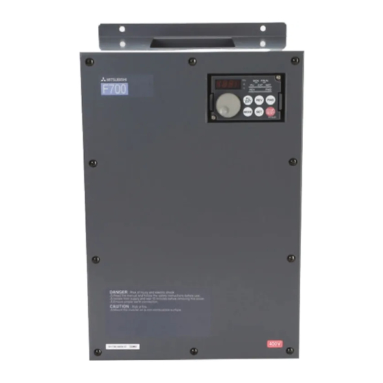
Description of the case Product checking and part identification Description of the case Cooling fan (refer to section 8.1.7) PU connector RS485 terminal (refer to section 3.5) Connector for plug-in option connection (Refer to the instruction manual of options) There are two connection connectors, called connector 1 and connector 2 from the top. -
Page 23: Accessory
Product checking and part identification Description of the case 1.2.1 Accessory Fan cover fixing screws Capacity Screw Size[mm] Number M3 × 35 00083/00126 M4 × 40 00170 to 00380 M4 × 50 00470/00620 Tab. 1-1: Fan cover fixing screws NOTES The fan cover fixing screws are not delivered with models 00620 or less. - Page 24 Description of the case Product checking and part identification 1 - 4...
-
Page 25: Installation
IP54. ● The operation panel (FR-DU07) is designed to IP54 specifications. Do not install the FR-DU07 mounted on the FR-F740 EC. Loosen the two screws on the operation panel. (These screws cannot be removed.) Push the left and right hooks of the operation panel and pull the operation panel toward you to remove. -
Page 26: Removal And Reinstallation Of The Front Cover
Removal and reinstallation of the front cover Installation Removal and reinstallation of the front cover 2.2.1 FR-F740-00023 to 00620-EC Removal Loosen the installation screws of the front cover. Pull the front cover toward you to remove by pushing an installation hook using left fixed hooks as supports. -
Page 27: Fr-F740-00770 To 12120-Ec
Installation Removal and reinstallation of the front cover 2.2.2 FR-F740-00770 to 12120-EC Removal Loosen the installation screws of the front cover 1. Loosen the installation screws of the front cover 2. Pull the front cover 2 toward you to remove by pushing an installation hook on the right side using left fixed hooks as supports. - Page 28 Removal and reinstallation of the front cover Installation Reinstallation Insert the two fixed hooks on the left side of the front cover 2 into the sockets of the inverter. Using the fixed hooks as supports, securely press the front cover 2 against the inverter. (Although installation can be done with the operation panel mounted, make sure that a connector is securely fixed.) Fix the front cover 2 with the installation screws.
-
Page 29: Fr-F746-00023 To 01160-Ec
Installation Removal and reinstallation of the front cover 2.2.3 FR-F746-00023 to 01160-EC Removal Loosen the installation screw of the front cover. Since the metal chain is mounted to the front cover, remove the front cover slowly. Remove the connection cable from the PU connector. Remove the hook of metal chain end from the inverter. -
Page 30: Mounting
Mounting Installation Mounting 00023 to 00620 00770 to 12120 CAUTION: When encasing multiple inverters, follow the instructions on page 2-11. Fix six positions for the FR-F740-04320 to 08660 and fix eight positions for the FR-F740-09620 to 12120. I000997E Fig. 2-8: Installation on the panel The inverter consists of precision mechanical and electronic parts. -
Page 31: Enclosure Design
Installation Enclosure design Enclosure design When an inverter enclosure is to be designed and manufactured, heat generated by contained equipment, etc., the environment of an operating place, and others must be fully considered to determine the enclosure structure, size and equipment layout. The inverter unit uses many semiconductor devices. - Page 32 Enclosure design Installation Humidity Normally operate the inverter within the 45 to 90% range of the ambient humidity. Too high hu- midity will pose problems of reduced insulation and metal corrosion. On the other hand, too low humidity may produce a spatial electrical breakdown. The insulation distance specified in JEM1103 "Control Equipment Insulator"...
- Page 33 Installation Enclosure design Explosive, flammable gases As the inverter is non-explosion proof, it must be contained in an explosion proof enclosure. In places where explosion may be caused by explosive gas, dust or dirt, an enclosure cannot be used unless it structurally complies with the guidelines and has passed the specified tests. This makes the enclosure itself expensive (including the test charges).
- Page 34 Enclosure design Installation Cooling system types for inverter enclosure From the enclosure that contains the inverter, the heat of the inverter and other equipment (transformers, lamps, resistors, etc.) and the incoming heat such as direct sunlight must be dis- sipated to keep the in-enclosure temperature lower than the permissible temperatures of the in- enclosure equipment including the inverter.
-
Page 35: Inverter Placement
Installation Enclosure design 2.4.2 Inverter placement Clearances around the inverter Always observe the specified minimum clearances to ensure good heat dissipation and ade- quate accessibility of the frequency inverter for servicing. Ambient temperature and humidity Clearances (side) Clearances (front) Measurement 01160 or less 01800 or more position... - Page 36 Enclosure design Installation Arrangement of multiple inverters When multiple inverters are placed in the same enclosure, generally arrange them horizontally as shown in the figure (a). When it is inevitable to arrange them vertically to minimize space, take such measures as to provide guides since heat from the bottom inverters can increase the tem- peratures in the top inverters, causing inverter failures.
-
Page 37: Heatsink Protrusion Attachment (Fr-A7Cn)
Installation Enclosure design 2.4.3 Heatsink protrusion attachment (FR-A7CN) When encasing the inverter in an enclosure, the generated heat amount in an enclosure can be greatly reduced by installing the heatsink portion of the inverter outside the enclosure. When in- stalling the inverter in a compact enclosure, etc., this installation method is recommended. For the FR-F740-00023 to 03610, a heatsink can be protruded outside the enclosure using a heatsink protrusion attachment (FR-A7CN). - Page 38 Enclosure design Installation Installation of the inverter Push the inverter heatsink portion outside the enclosure and fix the enclosure and inverter with upper and lower installation frame. * For the FR-F740-05470 or more, there are finger guards behind the enclosure. Therefore, Enclosure the thickness of the panel should be less than 10mm and also do not place anything around...
-
Page 39: Wiring
Wiring Inverter and peripheral devices Wiring Inverter and peripheral devices 3-phase AC power supply Use within the permissible power supply specifications of the inverter. (Refer to Appendix A.) Inverter (FR-F700 EC) The life of the inverter is influenced by ambient temperature. - Page 40 Inverter and peripheral devices Wiring NOTES Do not install a power factor correction capacitor or surge suppressor on the inverter output side. This will cause the inverter to trip or the capacitor and surge suppressor to be dam- aged. If any of the above devices are connected, immediately remove them. Electromagnetic Compatibility Operation of the frequency inverter can cause electromagnetic interference in the input and output that can be propagated by cable (via the power input lines), by wireless radiation to...
-
Page 41: Peripheral Devices
Wiring Inverter and peripheral devices 3.1.1 Peripheral devices Check the motor capacity of the inverter you purchased. Appropriate peripheral devices must be selected according to the capacity. Refer to the following list and prepare appropriate peripheral devices: Input side Breaker selection Magnetic Contactor Motor Applicable Inverter... - Page 42 Inverter and peripheral devices Wiring Selections for use of the Mitsubishi 4-pole standard motor with power supply voltage of 400V AC 50Hz. Select the MCCB according to the inverter power supply capacity. Install one MCCB per inverter. Fig. 3-2: Installation of the breakers MCCB F700 MCCB...
-
Page 43: Terminal Connection Diagram
Wiring Terminal connection diagram Terminal connection diagram Resistor unit 1 DC reactor Source Logic *6 A CN8 (for MT-BU5) (Option) Remove the jumper for the 01160 connector is provided with or less if a DC reactor is Brake unit Main circuit terminal the 01800 or more. - Page 44 Terminal connection diagram Wiring NOTES To prevent a malfunction due to noise, keep the signal cables more than 10cm away from the power cables. After wiring, wire offcuts must not be left in the inverter. Wire offcuts can cause an alarm, failure or malfunction. Always keep the inverter clean. When drilling mounting holes in an enclosure etc., take care not to allow chips and other for- eign matter to enter the inverter.
-
Page 45: Main Circuit Connection
Wiring Main circuit connection Main circuit connection 3.3.1 Specification of main circuit terminal Terminal Name Description L1, L2, L3 AC power input Connect to the commercial power supply (380–500V AC, 50/60Hz) Keep these terminals open when using the high power factor converter (FR-HC, MT-HC) or power regeneration common converter (FR-CV). -
Page 46: Terminal Layout And Wiring
Main circuit connection Wiring 3.3.2 Terminal layout and wiring FR-F740/746-00023 to 00126-EC FR-F740/746-00170 and 00250-EC Jumper Screw size M4 CHARGE lamp Jumper Jumper Jumper Screw size M4 CHARGE lamp L1 L2 L3 Screw size M4 Power supply Motor Power supply L1 L2 L3 Screw size M4 Motor... - Page 47 Wiring Main circuit connection FR-F740-03250 and 03610-EC FR-F740-04320 and 04810-EC Screw size M4 Screw size M4 CHARGE lamp CHARGE lamp Jumper Jumper Screw size M10 Screw size M12 Screw size Screw size Power supply Power supply Motor Motor DC reactor DC reactor Screw size M12 Screw size M12...
- Page 48 Main circuit connection Wiring Connection to the conductors When wiring the inverter main circuit conductor of the 05470 or more, tighten a nut from the right side of the conductor. When wiring two wires, place wires on both sides of the conductor. (Refer to the drawing below.) For wiring, use bolts (nuts) provided with the inverter.
-
Page 49: Cables And Wiring Length
Wiring Main circuit connection Cables and wiring length Select the recommended cable size to ensure that a voltage drop will be 2% max. If the wiring distance is long between the inverter and motor, a main circuit cable voltage drop will cause the motor torque to decrease especially at the output of a low frequency. - Page 50 Main circuit connection Wiring For the 01160 or less, the recommended cable size is that of the HIV cable (600V class 2 vinyl-insulated cable) with continuous maximum permissible temperature of 75°C. Assumes that the ambient temperature is 50°C or less and the wiring distance is 20m or less. For the 01800 or more, the recommended cable size is that of LMFC (heat resistant flexible cross-linked polyethylene insulated cable) with continuous maximum permissible tempera- ture of 95°C.
- Page 51 Wiring Main circuit connection Notes on earthing Leakage currents flow in the inverter or the EMC filter respectively. To prevent an electric shock, the inverter, input filter and motor must be earthed. (This inverter must be earthed. Earthing must conform to the requirements of national and local safety regulations and electrical codes. (JIS, NEC section 250, IEC 536 class 1 and other applicable standards)).
- Page 52 Main circuit connection Wiring Total wiring length The maximum possible length of the motor cables depends on the capacity of the inverter and the selected carrier frequency. The cables should never be longer than the maximum permis- sible length. The lengths in the following table are for unshielded cables. When shielded cables are use di- vide the values listed in the table by 2.
- Page 53 Wiring Main circuit connection ● To suppress the surge voltage at the inverter output, connect an output filter. Please contact your Mitsubishi dealer for more details. NOTES Especially for long-distance wiring, the inverter may be affected by a charging current caused by the stray capacitances of the wiring, leading to a malfunction of the overcurrent protective function or fast response current limit function, or a malfunction or fault of the equipment connected on the inverter output side.
-
Page 54: Control Circuit Specifications
Control circuit specifications Wiring Control circuit specifications The functions of the terminals highlighted in grey can be adjusted with parameters 178 to 196 "Input/Output terminal function assignment" (refer to section 6.9). The listed settings show the default configuration as shipped, which you can restore by resetting to the factory defaults. Input signals Rated Refer to... - Page 55 Wiring Control circuit specifications Rated Refer to Terminal Name Description Page Specifications 24V DC/0.1A output With negative logic and control via open col- lector transistors (e.g. a PLC) the positive pole Power supply 24V DC of an external power source must be con- voltage range: power supply, nected to the PC terminal.
- Page 56 Control circuit specifications Wiring Set Pr. 73, Pr. 267, and a voltage/current input switch correctly, then input an analog signal in accordance with the setting. Applying a voltage signal with voltage/current input switch on (current input is selected) or a current signal with switch off (voltage input is selected) could cause component damage of the inverter or analog circuit of signal output devices.
- Page 57 Wiring Control circuit specifications Output signals Rated Refer to Terminal Name Description Page Specifications Relay output 1 The alarm is output via relay contacts. The A1, B1, C1 6-120 Contact (alarm output) block diagram shows the normal operation and capacity: voltage free status.
- Page 58 Control circuit specifications Wiring Rated Refer to Terminal Name Description Page Specifications Load impedance: Analog current Select one e.g. output fre- 200Ω–450Ω 6-146 output quency from monitor items. Output signal: The output signal is propor- 0–20mA tional to the magnitude of Output signal: the corresponding monitor- Output item:...
-
Page 59: Control Circuit Terminals
Wiring Control circuit specifications 3.4.1 Control circuit terminals I001018E Fig. 3-8: Terminal layout Wiring method Remove about 6mm of the cable insulation. Wire the stripped cable after twisting it to prevent it from becoming loose. In addition, do not solder it. Fig. - Page 60 Control circuit specifications Wiring Common terminals of the control circuits PC, 5, SE Terminals PC, 5, and SE are all common terminals (0V) for I/O signals and are isolated from each other. Avoid connecting the terminal PC and 5 and the terminal SE and 5. Terminal PC is a common terminal for the contact input terminals (STF, STR, STOP, RH, RM, RL, JOG, RT, MRS, RES, AU, CS).
-
Page 61: Wiring Instructions
Wiring Control circuit specifications 3.4.2 Wiring instructions ● Use shielded or twisted cables for connection to the control circuit terminals and run them away from the main and power circuits (including the 230V relay sequence circuit). ● Use two or more parallel micro-signal contacts or twin contacts to prevent a contact faults when using contact inputs since the control circuit input signals are micro-currents. -
Page 62: Separate Power Supply For The Control Circuit
Control circuit specifications Wiring 3.4.3 Separate power supply for the control circuit In an alarm condition the frequency inverter’s integrated alarm relay only remains active as long as there is a mains power supply on terminals R/L1, S/L2 and T/L3. If you want the alarm signal to remain active after the frequency inverter has been switched off a separate power supply for the control circuit is required, which should be connected as shown in the circuit diagram below. - Page 63 Wiring Control circuit specifications FR-F740/746-00170 to 00250-EC Loosen the upper screws and then the lower screws Remove the jumpers Connect the separate power supply cable for the control circuit to the upper terminals R1/L11 and S1/L21. Main circuit terminals I001025E Fig.
- Page 64 Control circuit specifications Wiring Position of the power supply terminal block for the control circuit 00310, 00380 00470, 00620 00770 to 12120 Power supply terminal block for the control circuit I001027E Fig. 3-17: Position of the power supply terminal block for the control circuit CAUTION: ●...
-
Page 65: Changing The Control Logic
Wiring Control circuit specifications 3.4.4 Changing the control logic The input signals are set to source logic (SOURCE) when shipped from the factory. To change the control logic, the jumper connector on the control circuit terminal block must be moved to the other position. (The output signals may be used in either the sink or source logic independent of the jumper con- nector position.) I001028E... - Page 66 Control circuit specifications Wiring Sink logic and source logic ● In sink logic, a signal switches on when a current flows from the corresponding signal input terminal. Terminal SD is common to the contact input signals. Terminal SE is common to the open collector output signals.
- Page 67 Wiring Control circuit specifications Using an external power supply ● Sink logic type Use terminal PC as a common terminal to prevent a malfunction caused by undesirable current. (Do not connect terminal SD of the inverter with terminal 0V of the external power supply.
-
Page 68: Connecting The Operation Panel/Parameter Unit Using A Connection Cable
Connecting the operation panel/parameter unit using a connection cable Wiring Connecting the operation panel/parameter unit using a connection cable With a connection cable (FR-A5CBL), you can connect the operation panel (FR-DU07) or the parameter unit (FR-PU07) to the inverter. For mounting the operation panel (FR-DU07), the op- tional connector (FR-ADP) is required. -
Page 69: Rs485 Terminal Block
Wiring RS485 terminal block RS485 terminal block Specification Description Conforming standard EIA-485 (RS485) Transmission format Multidrop link Communication speed Max. 38400bps (76800bps for BACnet MS/TP protocol) Overall length 500m Connection cable Twisted pair cable (4 pairs) Tab. 3-11: Specifications of the RS485 terminal block Terminating resistor switch Factory-set to "OPEN". -
Page 70: Communication Operation
RS485 terminal block Wiring 3.6.1 Communication operation Using the PU connector or RS485 terminal, you can perform communication operation from a personal computer etc. When the PU connector is connected with a personal, FA or other com- puter by a communication cable, a user program can run and monitor the inverter or read and write to parameters. -
Page 71: Connection Of Stand-Alone Option Units
Wiring Connection of stand-alone option units Connection of stand-alone option units The inverter accepts a variety of stand-alone option units as required. CAUTION: Incorrect connection will cause inverter damage or accident. Connect and operate the option unit carefully in accordance with the corresponding option unit manual. 3.7.1 Magnetic contactors (MC) Inverter input side magnetic contactor (MC) - Page 72 Connection of stand-alone option units Wiring Example As shown below, always use the start signal (ON or OFF across terminals STF or STR-PC) to make a start or stop. (Refer to section 6.9.4.) Inverter Power To the supply motor Operation preparation Start-/Stop- Operation Stop...
-
Page 73: Connection Of A Brake Unit (Fr-Bu/Mt-Bu5)
Wiring Connection of stand-alone option units 3.7.2 Connection of a brake unit (FR-BU/MT-BU5) When connecting a brake unit to improve the brake capability at deceleration, make connection as shown below. Connection with the brake unit FR-BU (01160 or less) Inverter 3-phase AC power supply ≤... - Page 74 Connection of stand-alone option units Wiring Connection with the brake unit MT-BU5 (01800 or more) After making sure that the wiring is correct, set "1" in Pr. 30 "Regenerative function selection". (Refer to section 6.8.2) Inverter 3-phase AC power supply ≤...
- Page 75 Wiring Connection of stand-alone option units Inserting the CN8 connector Make cuts in the rubber bush for leading the CN8 connector cable with a nipper or cutter knife. Rubber bushes Make cuts in rubber bush I001348E Fig. 3-28: Rubber bush Insert a connector on the MT-BU5 side through a rubber bush to connect to a connector on the inverter side.
-
Page 76: Connection Of The High Power Factor Converter (Fr-Hc, Mt-Hc)
Connection of stand-alone option units Wiring 3.7.3 Connection of the high power factor converter (FR-HC, MT-HC) When connecting the high power factor converter (FR-HC) to suppress power harmonics, per- form wiring securely as shown below. CAUTION: Perform wiring of the high power factor converter (FR-HC) securely as shown below. Incorrect connection will damage the high power factor converter and inverter. - Page 77 Wiring Connection of stand-alone option units Connection with the MT-HC (01800 or more) Inverter 3-phase AC power supply Insulated transformer I001351E Fig. 3-31: Connection with the MT-HC Remove the jumper across terminals R-R1, S-S1 of the inverter, and connect the control circuit power supply to the R1 and S1 terminals.
-
Page 78: Connection Of The Power Regeneration Common Converter Fr-Cv
Connection of stand-alone option units Wiring 3.7.4 Connection of the power regeneration common converter FR-CV (01160 or less) When connecting the power regeneration common converter (FR-CV), make connection so that the inverter terminals (P/+, N/−) and the terminal symbols of the power regeneration common converter (FR-CV) are the same. -
Page 79: Connection Of Power Regeneration Converter (Mt-Rc) (01800 Or More)
Wiring Connection of stand-alone option units 3.7.5 Connection of power regeneration converter (MT-RC) (01800 or more) When connecting a power regeneration converter (MT-RC), perform wiring securely as shown below. CAUTION: Perform wiring of the power regeneration converter (MT-RC) securely as shown below. Incorrect connection will damage the power regeneration converter and inverter. -
Page 80: Connection Of The Power Improving Dc Reactor
Connection of stand-alone option units Wiring 3.7.6 Connection of the power improving DC reactor When using the DC reactor, connect it between terminals P1 and P/+. In this case, the jumper connected across terminals P1 and P/+ must be removed. Otherwise, the reactor will not exhibit its performance. -
Page 81: Installation Of A Reactor
Wiring Connection of stand-alone option units 3.7.7 Installation of a reactor When the inverter is connected near a large-capacity power transformer (1000kVA or more) or when a power capacitor is to be switched over, an excessive peak current may flow in the power input circuit, damaging the converter circuit. -
Page 82: Electromagnetic Compatibility (Emc)
Electromagnetic compatibility (EMC) Wiring Electromagnetic compatibility (EMC) 3.8.1 Leakage currents and countermeasures Mains filters, shielded motor cables, the motor, and the inverter itself cause stationary and var- iable leakage currents to PE. Since its value depends on the capacitances, carrier frequency, etc., low acoustic noise operation at the increased carrier frequency of the inverter will increase the leakage current. - Page 83 Wiring Electromagnetic compatibility (EMC) Line-to-line Thermal leakage currents relay path Power Inverter supply Line-to-line static capacitances I001043E Fig. 3-36: Line-to-line leakage currents ● Countermeasures – Use Pr. 9 "Electronic thermal O/L relay". – If the carrier frequency setting is high, decrease the Pr. 72 "PWM frequency selection" setting.
- Page 84 Electromagnetic compatibility (EMC) Wiring Note on selecting a suitable power supply ELCB If your application requires by installation standards an RCD (residual current device) as up stream protection please select according to DIN VDE 0100-530 as following: Single phase inverter type A or B Three phase inverter only type B Additionally, when selecting a residual current device (RCD), leakage current caused by the mains filter, the length of the shielded motor cable and the carrier frequency must be taken into...
- Page 85 Wiring Electromagnetic compatibility (EMC) Example 5.5mm² × 5m 5.5mm² × 60m Noise filter (optional) 3~, 400V, 2kW Inverter Ig1 Ign Breaker Designed for Harmonic Standard Breaker and Surge Suppression Leakage current Ig1 [mA] × × -- - ------------------- - 0.11 1000 m Leakage current Ign [mA] 0 (without additional noise filter)
- Page 86 Electromagnetic compatibility (EMC) Wiring NOTES The frequency inverter monitors its own output for ground faults up to a frequency of 120Hz. However, it is important to understand that this feature only protects the inverter itself. It can- not be used to provide protection against shock hazards for personnel. In the connection earthed-neutral system, the sensitivity current is purified against an earth fault in the inverter output side.
-
Page 87: Inverter-Generated Noises And Their Reduction Techniques
Wiring Electromagnetic compatibility (EMC) 3.8.2 Inverter-generated noises and their reduction techniques Some noises enter the inverter to malfunction it and others are radiated by the inverter to mal- function peripheral devices. Though the inverter is designed to be insusceptible to noises, it han- dles low-level signals, so it requires the following basic techniques. - Page 88 Electromagnetic compatibility (EMC) Wiring Inverter Noise directly radiated Air propagated ... Path generated noise from inverter noise Noise radiated from ... Path power supply cable Noise radiated from ... Path motor connection cable Electromagnetic ... Path induction noise Electrostatic ... Path induction noise Noise propagated Electrical path...
- Page 89 Wiring Electromagnetic compatibility (EMC) Noise Measures Propagation Path When devices that handle low-level signals and are liable to malfunction due to noises, e.g. instruments, receivers and sensors, are contained in the enclosure that contains the inverter or when their signal cables are run near the inverter, the devices may be malfunctioned by air- propagated noises.
-
Page 90: Emc Filter
Electromagnetic compatibility (EMC) Wiring 3.8.3 EMC filter The inverter is equipped with a built-in EMC filter. Effective for reduction of air-propagated noise on the input side of the inverter. The EMC filter is factory-set to enable (ON). To disable it, fit the EMC filter ON/OFF connector to the OFF position. -
Page 91: Power Supply Harmonics
Wiring Electromagnetic compatibility (EMC) 3.8.4 Power supply harmonics The inverter may generate power supply harmonics from its converter circuit to affect the power generator, power capacitor etc. Power supply harmonics are different from noise and leakage currents in source, frequency band and transmission path. Take the following countermeasure suppression techniques. -
Page 92: Inverter-Driven 400V Class Motor
Electromagnetic compatibility (EMC) Wiring 3.8.5 Inverter-driven 400V class motor In the PWM type inverter, a surge voltage attributable to wiring constants is generated at the mo- tor terminals. Especially for a 400V class motor, the surge voltage may deteriorate the insula- tion. -
Page 93: Operation
Operation Precautions for use of the inverter Operation Precautions for use of the inverter The FR-F700 series is a highly reliable product, but incorrect peripheral circuit making or op- eration/handling method may shorten the product life or damage the product. Before starting operation, always recheck the following items. - Page 94 Precautions for use of the inverter Operation ● A short circuit or earth fault on the inverter output side may damage the inverter modules. – Fully check the insulation resistance of the circuit prior to inverter operation since repeated short circuits caused by peripheral circuit inadequacy or an earth fault caused by wiring inadequacy or reduced motor insulation resistance may damage the inverter modules.
- Page 95 Operation Precautions for use of the inverter ● Handling of inverter output side magnetic contactor Switch the magnetic contactor between the inverter and motor only when both the inverter and motor are at a stop. When the magnetic contactor is turned ON while the inverter is operating, overcurrent protection of the inverter and such will activate.
-
Page 96: Drive The Motor
Drive the motor Operation Drive the motor The inverter needs frequency command and start command. Refer to the flow chart below to perform setting. Step of operation Installation/mounting Wiring of the power supply and motor System examination Start command using the PU connector and RS485 terminal of the inverter and plug-in option to give a start (Communication). -
Page 97: Operation Panel Fr-Du07
Operation Operation panel FR-DU07 Operation panel FR-DU07 4.3.1 Parts of the operation panel LED-Display 4-digit 7-segment display for opera- tional values, parameter numbers, etc. (For selecting a monitoring item set Pr. 52 and Pr. 774 to Pr. 776.) Unit indication LED to indicate the current unit Frequency (flickers when the set frequency monitor is displayed) - Page 98 Operation panel FR-DU07 Operation Function Description Used to change the frequency setting and parameter values. Push the setting dial to display the following items: The set frequency currently set Digital dial The present setting during calibration Last 8 fault history numbers in the faults history mode Rotation direction Run command forward rotation Rotation direction...
-
Page 99: Basic Operation (Factory Setting)
Operation Operation panel FR-DU07 4.3.2 Basic operation (factory setting) Operation mode switch over At powering on (external operation mode) PU Jog operation mode Example (Refer to page 4-17.) Value change and frequency flicker PU operation mode Frequency setting has been (output frequency monitor) written and completed! Output current monitor... -
Page 100: Easy Operation Mode Setting (Easy Setting Mode)
Operation panel FR-DU07 Operation 4.3.3 Easy operation mode setting (easy setting mode) A frequency inverter can be controlled alone via the parameter unit, through external signals (switch, SPC outputs, external setpoint sources, etc.) or through a combination of external sig- nals and inputs to the parameter unit. - Page 101 Operation Operation panel FR-DU07 Operation Method Operation Mode Operation Panel Indication Start Command Frequency Command PU Modes Flickering External External (Analog signal at External operation mode (STF-, STR) terminal 2 (voltage) or 4 (current)) Flickering Combined operation External (STF-, STR) mode 1 Flickering External...
-
Page 102: Operation Lock
Operation panel FR-DU07 Operation 4.3.4 Operation lock Operation using the digital dial and key of the operation panel can be made invalid to prevent pa- rameter change and unexpected start and stop. Operation procedure: Set "10" or "11" in Pr. 161, then press the MODE key for 2s to make the digital dial key operation invalid. - Page 103 Operation Operation panel FR-DU07 Operation Display Screen at powering on The monitor display appears. PU indication is lit. Press the PU/EXT key to choose the PU operation mode. The parameter number Press the MODE key to choose the parameter read previously appears.
-
Page 104: Monitoring Of Output Current And Output Voltage
Operation panel FR-DU07 Operation 4.3.5 Monitoring of output current and output voltage Monitor display of output frequency, output current and output voltage can be changed by push- ing the SET key during monitoring mode. Operation Display Press the MODE key during operation to choose the output frequency monitor. -
Page 105: Change The Parameter Setting Value
Operation Operation panel FR-DU07 4.3.8 Change the parameter setting value Example Change the Pr. 1 "Maximum frequency" setting from 120Hz to 50Hz. Operation Display Screen at powering on The monitor display appears. PU indication is lit. Press the PU/EXT key to choose the PU operation mode. - Page 106 Operation panel FR-DU07 Operation NOTES The number of digits displayed on the operation panel (FR-DU07) is four. Only the upper four digits of values can be displayed and set. If the values to be displayed have five digits or more including decimal places, the fifth or later numerals cannot be displayed nor set. For example: when Pr.
-
Page 107: Overheat Protection Of The Motor By The Inverter
Operation Overheat protection of the motor by the inverter Overheat protection of the motor by the inverter Set this parameter when using a motor other than the Mitsubishi standard motor (SF-JR) and Mitsubishi constant torque motor (SF-HRCA). Set the rated motor current in Pr. 9 "Electronic thermal O/L relay"... - Page 108 Overheat protection of the motor by the inverter Operation NOTES Protective function by electronic thermal relay function is reset by inverter power reset and reset signal input. Avoid unnecessary reset and power-off. When two or more motors are connected to the inverter, they cannot be protected by the electronic thermal relay function.
-
Page 109: Pu Operation Mode
Operation PU operation mode PU operation mode Fig. 4-11: Inverter PU operation mode Power Motor supply I001069E From where is the frequency command given? ● Operation at the frequency set in the frequency setting mode of the operation panel. (Refer to section 4.5.1.) ●... -
Page 110: Set The Set Frequency To Operate
PU operation mode Operation 4.5.1 Set the set frequency to operate Example Performing operation at 30Hz Operation Display Screen at powering on The monitor display appears. PU indication is lit. Press the PU/EXT key to choose the PU operation mode. Turn the digital dial to show the Flickers for about 5s. -
Page 111: Use The Digital Dial Like A Potentiometer To Perform Operation
Operation PU operation mode 4.5.2 Use the digital dial like a potentiometer to perform operation ● Set "0" (extended mode parameter valid) in Pr. 160 "User group read selection". ● Set "1" (setting dial potentiometer mode) in Pr. 161 "Frequency setting/key lock operation selection". -
Page 112: Use Switches To Give The Frequency Command (Multi-Speed Setting)
PU operation mode Operation 4.5.3 Use switches to give the frequency command (multi-speed setting) ● Pr. 79 "Operation mode selection" must be set to "4" (external/PU combined operation mode 2). ● Use the FWD or REV key to give a start command. ●... - Page 113 Operation PU operation mode Operation Display Screen at powering on The monitor display appears. The parameter number Press the MODE key to choose the parameter read previously setting mode. appears. Turn the digital dial until P.79 (Pr. 79) appears. Press the SET key to show the currently set value. The initial value "0"...
- Page 114 PU operation mode Operation Possible faults: ● 50Hz for the RH, 30Hz for the RL and 10Hz for the RL are not output when they are turned on. – Check for the setting of Pr. 4, Pr. 5, and Pr. 6 once again. –...
-
Page 115: Perform Frequency Setting By Analog Voltage Input
Operation PU operation mode 4.5.4 Perform frequency setting by analog voltage input ● Pr. 79 "Operation mode selection" must be set to "4" (external/PU combined operation mode 2). ● Use the FWD or REV key to give a start command. The frequency setting potentiometer is supplied with 5V of power from the inverter (terminal 10). - Page 116 PU operation mode Operation Operation Display Screen at powering on The monitor display appears. The parameter number Press the MODE key to choose the parameter read previously setting mode. appears. Turn the digital dial until P.79 (Pr. 79) appears. Press the SET key to show the currently set value. The initial value "0"...
-
Page 117: Perform Frequency Setting By Analog Current Input
Operation PU operation mode 4.5.5 Perform frequency setting by analog current input ● Pr. 79 "Operation mode selection" must be set to "4" (external/PU combined operation mode 2). ● Turn the AU signal on. ● Use the FWD or REV key to give a start command. Inverter Power Motor... - Page 118 PU operation mode Operation Operation Display Screen at powering on The monitor display appears. The parameter number Press the MODE key to choose the parameter read previously setting mode. appears. Turn the digital dial until P.79 (Pr. 79) appears. Press the SET key to show the currently set value. The initial value "0"...
-
Page 119: External Operation
Operation External operation External operation From where is the frequency command given? ● Operation at the frequency set in the frequency setting mode of the operation panel. (Refer to section 4.6.1.) ● Give a frequency command by switch (multi-speed setting). (Refer to section 4.6.2.) ●... - Page 120 External operation Operation Operation Display Screen at powering on The monitor display appears. The parameter number Press the MODE key to choose the parameter read previously setting mode. appears. Turn the digital dial until P.79 (Pr. 79) appears. Press the SET key to show the currently set value. The initial value "0"...
-
Page 121: Use Switches To Give A Start Command And A Frequency Command (Multi-Speed Setting) (Pr. 4 To Pr. 6)
Operation External operation 4.6.2 Use switches to give a start command and a frequency command (multi- speed setting) (Pr. 4 to Pr. 6) ● Start command by terminal STF (STR)-PC. ● Frequency command by terminal RH, RM, RL and STR-PC. ●... - Page 122 External operation Operation Example Set "40Hz" in Pr. 4 "Multi-speed setting (high speed)" and turn on terminals RH and STF (STR)-SD to operate. Operation Display Power on → operation mode check For the initial setting, the inverter operates in the external operation mode "EXT"...
- Page 123 Operation External operation Possible faults: ● The EXT lamp is not lit even when the PU/EXT key is pressed. – Switchover of the operation mode with is valid when Pr. 79 = 0 (initial value). ● 50Hz, 30Hz and 10Hz are not output from RH, RM and RL respectively when they are turned on. –...
-
Page 124: Perform Frequency Setting By Analog Voltage Input
External operation Operation 4.6.3 Perform frequency setting by analog voltage input The frequency setting potentiometer is supplied with 5V of power from the inverter (terminal 10). Inverter Power Motor supply Forward rotation start Reverse rotation start Frequency setting potentiometer I001090E Fig. - Page 125 Operation External operation Operation Display Power on → operation mode check For the initial setting, the inverter operates in the external operation mode "EXT" when powering on. Check that the operation command indication is "EXT". If not displayed, press the PU/EXT key to change to the external "EXT"...
- Page 126 External operation Operation Possible faults: ● The motor will not rotate. – Check that the EXT lamp is lit. The external operation mode is valid when Pr. 79 = 0 (initial value). Use the PU/EXT key to change into the external operation mode. –...
-
Page 127: Change The Frequency (50Hz) Of The Maximum Value Of Potentiometer
Operation External operation 4.6.4 Change the frequency (50Hz) of the maximum value of potentiometer (at 5V) Example The frequency of the maximum analog voltage of the potentiometer (at 5V) has to be changed from the initial setting of 50Hz to 40 Hz. Set 40Hz in Pr. 125. Operation Display Turn the digital dial until P.125 (Pr. -
Page 128: Perform Frequency Setting By Analog Current Input
External operation Operation 4.6.5 Perform frequency setting by analog current input ● Switch terminal STF (STR)-PC on to give a start command. ● Turn the AU signal on. ● Pr. 79 "Operation mode selection" must be set to "2" (external operation mode). Inverter Power Motor... - Page 129 Operation External operation Operation Display Power on → operation mode check For the initial setting, the inverter operates in the external operation mode "EXT" when powering on. Check that the operation command indication is "EXT". If not displayed, press the PU/EXT key to change to the external "EXT"...
-
Page 130: Change The Frequency (50Hz) Of The Maximum Value Of Potentiometer
External operation Operation 4.6.6 Change the frequency (50Hz) of the maximum value of potentiometer (at 20mA) Example The frequency of the maximum analog current of the potentiometer (at 20mA) has to be changed from the initial setting of 50Hz to 40 Hz. Set 40Hz in Pr. 126. Operation Display Turn the digital dial until P.126 (Pr. -
Page 131: Basic Settings
Basic settings Simple mode parameter list Basic settings Simple mode parameter list For simple variable-speed operation of the inverter, the initial setting of the parameters may be used as they are. Set the necessary parameters to meet the load and operational specifications. Parameter setting, change and check can be made from the operation panel (FR-DU07). - Page 132 Simple mode parameter list Basic settings Refer Incre- Initial Name Range Description ments value page The inverter output voltage is mini- Energy saving control 0/4/9 mized when using for fan and 5-10 selection pump applications. Operation mode Select the start command location 0/1/2/3/4/6/7 5-12 selection...
-
Page 133: Increase The Starting Torque (Pr. 0)
Basic settings Increase the starting torque (Pr. 0) Increase the starting torque (Pr. 0) Set this parameter when the motor with a load does not rotate, an alarm OL is output, resulting in an inverter trip due to OC1, etc. Setting Name Initial Value... - Page 134 Increase the starting torque (Pr. 0) Basic settings Operation Display Screen at powering on The monitor display appears. PU indication is lit. Press the PU/EXT key to choose the PU operation mode. The parameter number Press the MODE key to choose the parameter read previously appears.
-
Page 135: Limit The Maximum And Minimum Output Frequency (Pr. 1, Pr. 2)
Basic settings Limit the maximum and minimum output frequency (Pr. 1, Pr. 2) Limit the maximum and minimum output frequency (Pr. 1, Pr. 2) Setting Name Initial Value Description Range 01160 or less 120Hz Set the upper limit of the output Maximum frequency 0–120Hz frequency. - Page 136 Limit the maximum and minimum output frequency (Pr. 1, Pr. 2) Basic settings Operation Display Screen at powering on The monitor display appears. PU indication is lit. Press the PU/EXT key to choose the PU operation mode. The parameter number Press the MODE key to choose the parameter read previously appears.
-
Page 137: When The Rated Motor Frequency Is 60Hz (Pr. 3)
Basic settings When the rated motor frequency is 60Hz (Pr. 3) When the rated motor frequency is 60Hz (Pr. 3) First, check the motor rating plate. If a frequency given on the rating plate is "60Hz" only, always set Pr. 3 "Base frequency" to "60Hz". Name Initial Value Setting Range... -
Page 138: Change The Acceleration/Deceleration Time (Pr. 7, Pr. 8)
Change the acceleration/deceleration time (Pr. 7, Pr. 8) Basic settings Change the acceleration/deceleration time (Pr. 7, Pr. 8) Set in Pr. 7 "Acceleration time" a larger value for a slower speed increase and a smaller value for a faster speed increase. Set in Pr. - Page 139 Basic settings Change the acceleration/deceleration time (Pr. 7, Pr. 8) Operation Display Screen at powering on The monitor display appears. PU indication is lit. Press the PU/EXT key to choose the PU operation mode. The parameter number Press the MODE key to choose the parameter read previously appears.
-
Page 140: Energy Saving Operation (Pr. 60)
When "9" is set in Pr. 60, the inverter operates in the optimum excitation control mode. This exclusive Mitsubishi Electric control method reduces motor losses in the low-load operating range and at frequencies below the motor’s rated frequency, thus operating the motor with op- timum efficiency. - Page 141 Basic settings Energy saving operation (Pr. 60) Example Selecting the energy saving operation mode. Operation Display Screen at powering on The monitor display appears. PU indication is lit. Press the PU/EXT key to choose the PU operation mode. The parameter number Press the MODE key to choose the parameter read previously appears.
-
Page 142: Operation Mode (Pr. 79)
Operation mode (Pr. 79) Basic settings Operation mode (Pr. 79) Select the operation command location and frequency command location. LED Indication Initial Setting : OFF Name Description Value Range : ON PU operation mode External/PU switch over mode External operation mode Press the PU/EXT key to switch between the PU and external operation mode. -
Page 143: Parameter Clear
Basic settings Parameter clear Parameter clear ● Set "1" in Pr.CL "Parameter clear" to initialize all parameters. (Parameters are not cleared when "1" is set in Pr. 77 "Parameter write selection". In addition, calibration parameters are not cleared.) ● Refer to Tab. 6-1 for parameters to be cleared with this operation. Operation Display Screen at powering on... -
Page 144: All Parameter Clear
All parameter clear Basic settings All parameter clear ● Set "1" in ALLC "All parameter clear" to initialize all parameters. (Parameters are not cleared when "1" is set in Pr. 77 "Parameter write selection". In addition, calibration parameters are not cleared.) ●... -
Page 145: Parameter Copy And Parameter Verification
Basic settings Parameter copy and parameter verification 5.10 Parameter copy and parameter verification PCPY Setting Description Cancel Copy the source parameters to the operation panel. Write the parameters copied to the operation panel into the destination inverter. Verify parameters in the inverter and operation panel. Tab. -
Page 146: Parameter Copy
Parameter copy and parameter verification Basic settings 5.10.1 Parameter copy Multiple inverters and parameter settings can be copied. Operation Display Connect the operation panel to the copy source inverter. Connect it during a stop. The parameter number Press the MODE key to choose the parameter read previously setting mode. - Page 147 Basic settings Parameter copy and parameter verification Possible faults: ● "rE1" appears. – A parameter read error has occurred. Perform operation in Fig. 5-11 from step again. ● "rE2" appears. – A parameter write error has occurred. Perform operation in Fig. 5-11 from step again.
-
Page 148: Parameter Verification
Parameter copy and parameter verification Basic settings 5.10.2 Parameter verification Whether same parameter values are set in other inverters or not can be checked. Operation Display Replace the operation panel on the inverter to be verified Replace it during a stop. Screen at powering on The monitor display appears. -
Page 149: Initial Value Change List
Basic settings Initial value change list 5.11 Initial value change list Displays and sets the parameters changed from the initial value. NOTES Calibration parameters (C0 (Pr. 900) to C7 (Pr. 905), C42 (Pr. 934) to C45 (Pr. 935)) are not displayed even they are changed from the initial settings. - Page 150 Initial value change list Basic settings Operation Display Screen at powering on The monitor display appears. PU indication is lit. Press the PU/EXT key to choose the PU EXT NET operation mode. Press the MODE key to choose the parameter setting mode.
-
Page 151: Parameter
Parameter Parameter overview Parameter Parameter overview Parameter 160 is factory set to "9999". That means that only the parameters marked with the following table are accessible. Set parameter 160 to "0" to access other or all parameters. The half-tone screened parameters allow its setting to be changed during operation even if "0" (initial value) is set in Pr. - Page 152 Parameter overview Parameter Para- Para- para- Parameter meter meter meter copy clear Refer clear Func- Incre- Initial Setting Name Description tion ments Value Range page ✔: enabled —: disabled Multi-speed setting Set frequency when the RH signal ✔ ✔ ✔ 0.01Hz 50Hz 0–400Hz...
- Page 153 Parameter Parameter overview Para- Para- para- Parameter meter meter meter copy clear Refer clear Func- Incre- Initial Setting Description Name tion ments Value Range page ✔: enabled —: disabled Set the rated motor current. Rated Electronic thermal O/L 0.01/ 0–500/ * The setting depends on the ✔...
- Page 154 Parameter overview Parameter Para- Para- para- Parameter meter meter meter copy clear Refer clear Func- Incre- Initial Setting Description Name tion ments Value Range page ✔: enabled —: disabled Open input always ✔ ✔ ✔ MRS input selection 6-112 Normally closed input (NC contact input specifications) Refer to Pr.
- Page 155 Parameter Parameter overview Para- Para- para- Parameter meter meter meter copy clear Refer clear Func- Incre- Initial Setting Description Name tion ments Value Range page ✔: enabled —: disabled Linear acceleration/deceleration S-pattern acceleration/ deceleration A Acceleration/decelera- S-pattern acceleration/ ✔ ✔ ✔...
- Page 156 Parameter overview Parameter Para- Para- para- Parameter meter meter meter copy clear Refer clear Func- Incre- Initial Setting Description Name tion ments Value Range page ✔: enabled —: disabled Up-to-frequency Set the level where the SU signal ✔ ✔ ✔ 0.1% 0–100% sensitivity (SU output)
- Page 157 Parameter Parameter overview Para- Para- para- Parameter meter meter meter copy clear Refer clear Func- Incre- Initial Setting Description Name tion ments Value Range page ✔: enabled —: disabled 1–3/5/6/ Select the monitor output to CA terminal function 8–14/17/21/ terminal CA. ✔...
- Page 158 Parameter overview Parameter Para- Para- para- Parameter meter meter meter copy clear Refer clear Func- Incre- Initial Setting Description Name tion ments Value Range page ✔: enabled —: disabled RH, RM, Frequency setting RL signal storage function function Multi-speed — setting Remote setting...
- Page 159 Parameter Parameter overview Para- Para- para- Parameter meter meter meter copy clear Refer clear Func- Incre- Initial Setting Description Name tion ments Value Range page ✔: enabled —: disabled PWM carrier frequency can be changed. The setting displayed is in [kHz]. Note that 0 indicates PWM frequency 0–15/ 0.7kHz, 15 indicates 14.5kHz and...
- Page 160 Parameter overview Parameter Para- Para- para- Parameter meter meter meter copy clear Refer clear Func- Incre- Initial Setting Description Name tion ments Value Range page ✔: enabled —: disabled Input specification (0 to 5V, 0 to 10V) of terminal 2 and 1 can be 6-188 ✔...
- Page 161 Parameter Parameter overview Para- Para- para- Parameter meter meter meter copy clear Refer clear Func- Incre- Initial Setting Description Name tion ments Value Range page ✔: enabled —: disabled The primary delay filter time con- stant for the analog input can be Input filter time ✔...
- Page 162 Parameter overview Parameter Para- Para- para- Parameter meter meter meter copy clear Refer clear Func- Incre- Initial Setting Description Name tion ments Value Range page ✔: enabled —: disabled External/PU switch over mode Fixed to PU operation mode Fixed to External operation mode External/PU combined operation Operation mode mode 1...
- Page 163 Parameter Parameter overview Para- Para- para- Parameter meter meter meter copy clear Refer clear Func- Incre- Initial Setting Description Name tion ments Value Range page ✔: enabled —: disabled Specify the inverter station number. Set the inverter station PU communication ✔...
- Page 164 Parameter overview Parameter Para- Para- para- Parameter meter meter meter copy clear Refer clear Func- Incre- Initial Setting Description Name tion ments Value Range page ✔: enabled —: disabled Without CR/LF PU communication ✔ ✔ ✔ CR/LF presence/ With CR absence selection With CR/LF Set the inverter station number...
- Page 165 Parameter Parameter overview Para- Para- para- Parameter meter meter meter copy clear Refer clear Func- Incre- Initial Setting Description Name tion ments Value Range page ✔: enabled —: disabled Terminal 2 frequency Set the frequency of terminal 2 input ✔ ✔...
- Page 166 Parameter overview Parameter Para- Para- para- Parameter meter meter meter copy clear Refer clear Func- Incre- Initial Setting Description Name tion ments Value Range page ✔: enabled —: disabled If the proportional band is narrow (parameter setting is small), the manipulated variable varies greatly with a slight change of the meas- ured value.
- Page 167 Parameter Parameter overview Para- Para- para- Parameter meter meter meter copy clear Refer clear Func- Incre- Initial Setting Description Name tion ments Value Range page ✔: enabled —: disabled Time required for only the differ- ential (D) action to provide the same manipulated variable as that 0.01–10.00s for the proportional (P) action.
- Page 168 Parameter overview Parameter Para- Para- para- Parameter meter meter meter copy clear Refer clear Func- Incre- Initial Setting Description Name tion ments Value Range page ✔: enabled —: disabled Without commercial power-sup- Commercial power ply switchover sequence supply switchover ✔ ✔...
- Page 169 Parameter Parameter overview Para- Para- para- Parameter meter meter meter copy clear Refer clear Func- Incre- Initial Setting Description Name tion ments Value Range page ✔: enabled —: disabled – Refer to Pr. 29 — Refer to Pr. 37 Japanese English German French...
- Page 170 Parameter overview Parameter Para- Para- para- Parameter meter meter meter copy clear Refer clear Func- Incre- Initial Setting Description Name tion ments Value Range page ✔: enabled —: disabled — Refer to Pr. 22 and Pr. 23 Second function is immediately made valid with on of the RT (X9) signal.
- Page 171 Parameter Parameter overview Para- Para- para- Parameter meter meter meter copy clear Refer clear Func- Incre- Initial Setting Description Name tion ments Value Range page ✔: enabled —: disabled 0–8/10–14/ 0: Low-speed operation 16/24/25/ command 37/50/51/ 1: Middle-speed operation STF terminal function ✔...
- Page 172 Parameter overview Parameter Para- Para- para- Parameter meter meter meter copy clear Refer clear Func- Incre- Initial Setting Description Name tion ments Value Range page ✔: enabled —: disabled 0/100: Inverter running 1/101: Up to frequency 2/102: Instantaneous power failure/under voltage RUN terminal function 3/103: Overload alarm ✔...
- Page 173 Parameter Parameter overview Para- Para- para- Parameter meter meter meter copy clear Refer clear Func- Incre- Initial Setting Description Name tion ments Value Range page ✔: enabled —: disabled – Refer to Pr. 4 to Pr. 6 — Refer to Pr. 72 Displayed in Select the unit for Analog input display...
- Page 174 Parameter overview Parameter Para- Para- para- Parameter meter meter meter copy clear Refer clear Func- Incre- Initial Setting Description Name tion ments Value Range page ✔: enabled —: disabled The motor is STF signal: coasted to a Forward rotation stop when the start 0–100s preset time...
- Page 175 Parameter Parameter overview Para- Para- para- Parameter meter meter meter copy clear Refer clear Func- Incre- Initial Setting Description Name tion ments Value Range page ✔: enabled —: disabled — Refer to Pr. 73 Display whether the control circuit capacitor, main circuit capacitor, Life alarm status cooling fan, and each parts of the (0–15)
- Page 176 Parameter overview Parameter Para- Para- para- Parameter meter meter meter copy clear Refer clear Func- Incre- Initial Setting Name Description tion ments Value Range page ✔: enabled —: disabled Refer to Pr. 73 — Refer to Pr. 52 Parameter for manufacturer setting: Do not set! Select restriction level of parame- 0–6/99/ 100–106/...
- Page 177 Parameter Parameter overview Para- Para- para- Parameter meter meter meter copy clear Refer clear Func- Incre- Initial Setting Description Name tion ments Value Range page ✔: enabled —: disabled PLC function is invalid PLC function operation PLC function is valid ✔...
- Page 178 Parameter overview Parameter Para- Para- para- Parameter meter meter meter copy clear Refer clear Func- Incre- Initial Setting Name Description tion ments Value Range page ✔: enabled —: disabled You can select Coasts to stop the inverter Decelerates to Operation selection at operation if a ✔...
- Page 179 Parameter Parameter overview Para- Para- para- Parameter meter meter meter copy clear Refer clear Func- Incre- Initial Setting Description Name tion ments Value Range page ✔: enabled —: disabled — Refer to Pr. 52 SLD: Ambient temperature 40°C, overload 110% 60s, 120% 3s ✔...
- Page 180 Parameter overview Parameter Para- Para- para- Parameter meter meter meter copy clear Refer clear Func- Incre- Initial Setting Description Name tion ments Value Range page ✔: enabled —: disabled Traverse function invalid Traverse function is valid only in Traverse function ✔...
- Page 181 Parameter Parameter overview Para- Para- para- Parameter meter meter meter copy clear Refer clear Func- Incre- Initial Setting Description Name tion ments Value Range page ✔: enabled —: disabled PID reverse Deviation value 10 , 110 action signal (terminal 1) (Input specifica- PID forward tion for the termi-...
- Page 182 Parameter overview Parameter Para- Para- para- Parameter meter meter meter copy clear Refer clear Func- Incre- Initial Setting Description Name tion ments Value Range page ✔: enabled —: disabled Set the frequency at which the control is automatically changed 0–400Hz Second PID control to PID control while the RT signals ✔...
- Page 183 Parameter Parameter overview Para- Para- para- Parameter meter meter meter copy clear Refer clear Func- Incre- Initial Setting Description Name tion ments Value Range page ✔: enabled —: disabled When the pre-charged amount exceeds Pr. 763 or the pre- charged time exceeds Pr. 764, the output is immediately shutoff, and Pre-charge fault the fault (E.PCH) is output.
- Page 184 Parameter overview Parameter Para- Para- para- Parameter meter meter meter copy clear Refer clear Func- Incre- Initial Setting Description Name tion ments Value Range page ✔: enabled —: disabled When the pre-charged amount exceeds Pr. 768 or the pre- charged time exceeds Pr. 769 while the RT signal is ON, the out- put is immediately shutoff, and the Second pre-charge...
- Page 185 Parameter Parameter overview Para- Para- para- Parameter meter meter meter copy clear Refer clear Func- Incre- Initial Setting Description Name tion ments Value Range page ✔: enabled —: disabled Regeneration avoidance function ✔ ✔ ✔ Regeneration invalid avoidance operation Regeneration avoidance function ✔...
- Page 186 Parameter overview Parameter Para- Para- para- Parameter meter meter meter copy clear Refer clear Func- Incre- Initial Setting Description Name tion ments Value Range page ✔: enabled —: disabled Refer to Pr. 52 Set the load factor for commercial power-supply operation. This value is used to calculate the ✔...
- Page 187 Parameter Parameter overview Para- Para- para- Parameter meter meter meter copy clear Refer clear Func- Incre- Initial Setting Description Name tion ments Value Range page ✔: enabled —: disabled Terminal 2 frequency (902) setting bias frequency Terminal 2 frequency (902) setting bias Terminal 2 frequency (903)
- Page 188 Parameter overview Parameter Para- Para- para- Parameter meter meter meter copy clear Refer clear Func- Incre- Initial Setting Description Name tion ments Value Range page ✔: enabled —: disabled Contrast adjustment of the LCD of PU contrast the parameter unit (FR-PU04/ ✔...
-
Page 189: Motor Torque
Parameter Motor torque Motor torque Refer to Purpose Parameter that must be set Section Set starting torque manually Manual torque boost Pr. 0, Pr. 46 6.2.1 Automatically control output current Simple magnetic flux vector control Pr. 71, Pr. 80, 6.2.2 according to load Pr. - Page 190 Motor torque Parameter Starting torque adjustment The set value indicates the percentage of the maximum output voltage at 0Hz by which the out- put voltage is increased. The voltage increases in direct proportion to the frequency from the time of startup until the operating frequency and voltage have been reached. Fig.
- Page 191 Parameter Motor torque NOTES Changing the terminal assignment using Pr. 178 to Pr. 189 "Input terminal function selec- tion" may affect the other functions. Please make setting after confirming the function of each terminal. The RT signal is assigned to the RT terminal in the default setting. By setting "3" to any of Pr.
-
Page 192: Simple Magnetic Flux Vector Control (Pr. 80, Pr. 90)
Motor torque Parameter 6.2.2 Simple magnetic flux vector control (Pr. 80, Pr. 90) Providing optimum excitation to the motor can also produce high torque in a low-speed range. (Simple magnetic flux vector control) Initial Refer to Name Setting Range Description Parameters referred to Value Section... -
Page 193: Slip Compensation (Pr. 245 To Pr. 247)
Parameter Motor torque 6.2.3 Slip compensation (Pr. 245 to Pr. 247) The inverter output current may be used to assume motor slip to keep the motor speed constant. Initial Refer to Name Setting Range Description Parameters referred to Value Section 0.01–50% Used to set the rated motor slip. -
Page 194: Stall Prevention
Motor torque Parameter 6.2.4 Stall prevention operation (Pr. 22, Pr. 23, Pr. 48, Pr. 49, Pr. 66, Pr. 148, Pr. 149, Pr. 154, Pr. 156, Pr. 157) This function monitors the output current and automatically changes the output frequency to prevent the inverter from coming to an alarm stop due to overcurrent, over voltage, etc. - Page 195 Parameter Motor torque Setting of stall prevention operation level (Pr. 22) Set in Pr. 22 the ratio of the output current to the rated inverter current at which stall prevention operation will be performed. Normally set 110% (initial value). Stall prevention operation stops acceleration (makes deceleration) during acceleration, makes deceleration during constant speed, and stops deceleration during deceleration.
- Page 196 Motor torque Parameter Stall prevention operation signal output and output timing adjustment (OL signal, Pr. 157) When the output power exceeds the stall prevention operation level and stall prevention is ac- tivated, the stall prevention operation signal (OL signal) turns on for longer than 100ms. When the output power falls to or below the stall prevention operation level, the output signal turns off.
- Page 197 Parameter Motor torque Setting of stall prevention operation in high frequency region (Pr. 22, Pr. 23, Pr. 66) During high-speed operation above the rated motor frequency, acceleration may not be made because the motor current does not increase. If operation is performed in a high frequency range, the current at motor lockup becomes smaller than the rated output current of the inverter, and the protective function (OL) is not executed if the motor is at a stop.
- Page 198 Motor torque Parameter Set multiple stall prevention operation levels (Pr. 48, Pr. 49) Setting "9999" in Pr. 49 "Second stall prevention operation frequency" and turning the RT signal on make Pr. 48 "Second stall prevention operation current" valid. Fig. 6-6: Second stall prevention operation current setting example Pr.
- Page 199 Parameter Motor torque Fig. 6-7: Stall prevention level, when the set frequency exceeds the value of Pr. 49 > Pr. 49 Output frequency [Hz] Output frequency frequency Pr. 49 Time Stall Pr. 22 prevention used level Pr. 48 used I001123E Fig.
- Page 200 Motor torque Parameter Stall prevention operation level setting by terminal 1 (Pr. 148, Pr. 149) Set Pr. 22 to "9999". Input 0 to 5V (or 0 to 10V) to terminal 1. Select 5V or 10V using Pr. 73 "Analog input selection".
- Page 201 Parameter Motor torque Limit the stall prevention operation and fast-response current limit operation according to the operating status (Pr. 156) Refer to the following table and select whether fast-response current limit operation will be per- formed or not and the operation to be performed at OL signal output: Stall Prevention Operation Level OL Signal Output Pr.
- Page 202 Motor torque Parameter NOTES When the load is heavy, when the lift is predetermined, or when the acceleration/decelera- tion time is short, stall prevention is activated and acceleration/deceleration may not be made according to the preset acceleration/deceleration time. Set Pr. 156 and stall preven- tion operation level to the optimum values.
-
Page 203: Multiple Rating (Ld = Light Duty, Sld = Super Light Duty) (Pr. 570)
Parameter Motor torque 6.2.5 Multiple rating (LD = Light Duty, SLD = Super Light Duty) (Pr. 570) You can use the inverter by changing the overload current rating specifications according to load applications. Note that the control rating of each function changes. Setting Refer to Name... -
Page 204: Limit The Output Frequency
Limit the output frequency Parameter Limit the output frequency Refer to Purpose Parameters that must be set Section Set upper limit and lower limit of output Maximum/minimum frequency Pr. 1, Pr. 2, 6.3.1 frequency Pr. 18 Perform operation by avoiding machine Frequency jump Pr. - Page 205 Parameter Limit the output frequency Set the minimum frequency Use Pr. 2 "Minimum frequency" to set the lower limit of the output frequency. NOTES When Pr. 15 "Jog frequency" is equal to or less than Pr. 2, the Pr. 15 setting has precedence over the Pr.
-
Page 206: Avoid Mechanical Resonance Points (Frequency Jump)
Limit the output frequency Parameter 6.3.2 Avoid mechanical resonance points (Frequency jump) (Pr. 31 to Pr. 36) When it is desired to avoid resonance attributable to the natural frequency of a mechanical sys- tem, these parameters allow resonant frequencies to be jumped. Refer to Name Initial Value... - Page 207 Parameter Limit the output frequency The following diagrams show how the jump point is selected. The diagram on the left shows a sequence in which the jump takes place at the end of the area to be jumped, for which the lower frequency must be entered first.
-
Page 208: Set V/F Pattern
Set V/f pattern Parameter Set V/f pattern Refer to Purpose Parameters that must be set Section Set motor ratings Base frequency, Base frequency voltage Pr. 3, Pr. 19, 6.4.1 Pr. 47 Select a V/F pattern according to Load pattern selection Pr. - Page 209 Parameter Set V/f pattern Set multiple base frequencies (Pr. 47) Use the second base frequency when you want to change the base frequency, e.g. when using multiple motors by switching between them by one inverter. Pr. 47 "Second V/f (base frequency)" is valid when the RT signal is on. NOTES The RT signal acts as the second function selection signal and makes the other second functions valid.
-
Page 210: Load Pattern Selection (Pr. 14)
Set V/f pattern Parameter 6.4.2 Load pattern selection (Pr. 14) You can select the optimum output characteristic (V/f characteristic) for the application and load characteristics. Initial Refer to Name Setting Range Description Parameters referred to Value Section For constant torque load Base frequency 6.4.1 Load pattern selection... -
Page 211: Adjustable 5 Points V/F (Pr. 71, Pr. 100 To Pr. 109)
Parameter Set V/f pattern 6.4.3 Adjustable 5 points V/f (Pr. 71, Pr. 100 to Pr. 109) A dedicated V/f pattern can be made by freely setting the V/f characteristic between a start-up and the base frequency and base voltage under V/f control (frequency voltage/frequency). The torque pattern that is optimum for the machine’s characteristic can be set. - Page 212 Set V/f pattern Parameter CAUTION: Set this parameter correctly according to the motor used. Incorrect setting may cause the motor to overheat and burn. Setting procedure: Set the rated motor current in Pr. 19 "Base frequency voltage". (No function at the setting of "9999"...
-
Page 213: Frequency Setting By External Terminals
Parameter Frequency setting by external terminals Frequency setting by external terminals Refer to Purpose Parameters that must be set Section Make frequency setting by combina- Multi-speed operation Pr. 4–Pr. 6, 6.5.1 tion of terminals Pr. 24–Pr. 27 Pr. 232–Pr. 239 Perform jog operation Jog operation Pr. - Page 214 Frequency setting by external terminals Parameter Operation is performed at the frequency set in Pr. 4 when the RH signal turns on, Pr. 5 when the RM signal turns on, and Pr. 6 when the RL signal turns on. Frequency from speed 4 to speed 15 can be set according to the combination of the RH, RM, RL and REX signals.
- Page 215 Parameter Frequency setting by external terminals Fig. 6-19: Connection example Forward rotation I001127E NOTES The priorities of the frequency commands by the external signals are "jog operation > multi- speed operation > terminal 4 analog input > terminal 2 analog input". (Refer to section 6.15 for the frequency command by analog input.) Valid in external operation mode or PU/external combined operation mode (Pr.
-
Page 216: Jog Operation (Pr. 15, Pr. 16)
Frequency setting by external terminals Parameter 6.5.2 Jog operation (Pr. 15, Pr. 16) Jog operation is used to setup the machine.The frequency and acceleration/deceleration time for Jog operation can be set. As soon as the frequency inverter receives the start signal, the mo- tor is accelerated at the frequency entered in parameter 15 (jog frequency) using the preset ac- celeration/brake time (parameter 16). - Page 217 Parameter Frequency setting by external terminals Fig. 6-21: Jog operation signal timing chart frequency Forward rotation Pr. 20 Pr. 15 Pr. 16 Reverse rotation I001324C Operation Display Screen at powering on Confirm that the external operation mode is selected. (EXT indication is lit) If not displayed, press the PU/EXT key to change to the external operation mode If the operation mode still does not change, set Pr.
- Page 218 Frequency setting by external terminals Parameter JOG operation from PU Set the PU (FR-DU07/FR-PU04/FR-PU07) to the jog operation mode. Operation is performed only while the start button is pressed. Fig. 6-23: Inverter Connection example for jog operation Power performed from PU Motor supply I001130E...
- Page 219 Parameter Frequency setting by external terminals NOTES When Pr. 29 "Acceleration/deceleration pattern selection" = "1" (S-pattern acceleration/ deceleration A), the acceleration/deceleration time is the period of time required to reach Pr. 3 "Base frequency". The Pr. 15 setting should be equal to or higher than the Pr. 13 "Starting frequency setting". The JOG signal can be assigned to the input terminal using any of Pr.
-
Page 220: Input Compensation Of Multi-Speed And Remote Setting (Pr. 28)
Frequency setting by external terminals Parameter 6.5.3 Input compensation of multi-speed and remote setting (Pr. 28) By inputting the frequency setting compensation signal (terminal 1, 2), the speed (frequency) can be compensated for relative to the multi-speed setting or the speed setting by remote setting function. -
Page 221: Remote Setting Function (Pr. 59)
Parameter Frequency setting by external terminals 6.5.4 Remote setting function (Pr. 59) Even if the operation panel is located away from the enclosure, you can use contact signals to perform continuous variable-speed operation, without using analog signals. Description Initial Setting Deceleration to Refer to Frequency set-... - Page 222 Frequency setting by external terminals Parameter When Pr. 59 is set to any of "1 to 3, 11 to 13" (remote setting function valid), the functions of the RH, RM and RL signals are changed: RH ⇒ acceleration, RM ⇒ deceleration and RL ⇒ clear. Pr.
- Page 223 Parameter Frequency setting by external terminals Frequency setting storage The frequency setting storage function stores the remote setting frequency (frequency set by RH/RM operation) into the memory (E²PROM). When power is switched off once, then on, op- eration is resumed with that output frequency value. (Pr. 59 = 1, 11) The frequency is stored at the point when the start signal (STF or STR) turns off or every one minute after one minute has elapsed since turn off (on) of both the RH (acceleration) and RM (deceleration) signals.
- Page 224 Frequency setting by external terminals Parameter During jog operation or PID control operation, the remote setting function is invalid. Set frequency = 0Hz ● Even when the remotely-set frequency is cleared by turning on the RL (clear) signal after turn off (on) of both the RH and RM signals, the inverter operates at the remotely-set frequency stored in the last operation if power is reapplied before one minute has elapsed since turn off (on) of both the RH and RM signals.
-
Page 225: Acceleration And Deceleration
Parameter Acceleration and deceleration Acceleration and deceleration Refer to Purpose Parameters that must be set Section Motor acceleration/deceleration Acceleration/deceleration times Pr. 7, Pr. 8, 6.6.1 time setting Pr. 20, Pr. 21, Pr. 44, Pr. 45, Pr. 147 Starting frequency Starting frequency and start-time hold Pr. - Page 226 Acceleration and deceleration Parameter Acceleration time setting (Pr. 7, Pr. 20) Use Pr. 7 "Acceleration time" to set the acceleration time required to reach Pr. 20 "Acceleration/ deceleration reference frequency" from 0Hz. Fig. 6-30: Acceleration/deceleration time Pr. 20 Pr. 7 Pr.
- Page 227 Parameter Acceleration and deceleration Change the setting range and increments of the acceleration/deceleration time (Pr. 21) Use Pr. 21 to set the acceleration/deceleration time and minimum setting range. Setting "0" (initial value)..... 0 to 3600s (minimum setting increments 0.1s) Setting "1" ........0 to 360s (minimum setting increments 0.01s) CAUTION: Changing the Pr.
- Page 228 Acceleration and deceleration Parameter Output frequency [Hz] frequency Pr. 147 Time Pr. 7 Pr. 44 Pr. 44 Pr. 8 Pr. 7 Pr. 44 Pr. 44 Pr. 8 (Pr. 45) (Pr. 45) RT signal I001929E Fig. 6-31: Automatic switching of the acceleration/deceleration time S-shaped acceleration/deceleration pattern If a S-shaped acceleration/deceleration pattern A is selected in pr.
-
Page 229: Starting Frequency And Start-Time Hold Function (Pr. 13, Pr. 571)
Parameter Acceleration and deceleration 6.6.2 Starting frequency and start-time hold function (Pr. 13, Pr. 571) You can set the starting frequency and hold the set starting frequency for a certain period of time. Set these functions when you need the starting torque or want to smooth motor drive at a start. Refer to Name Initial Value... - Page 230 Acceleration and deceleration Parameter Start-time hold function (Pr. 571) This function holds the time set in Pr. 571 and the output frequency set in Pr. 13 "Starting fre- quency". This function performs initial excitation to smooth the motor drive at a start. Forward rotation Output frequency [Hz]...
-
Page 231: Acceleration And Deceleration Pattern (Pr. 29, Pr. 140 To Pr. 143)
Parameter Acceleration and deceleration 6.6.3 Acceleration and deceleration pattern (Pr. 29, Pr. 140 to Pr. 143) You can set the acceleration/deceleration pattern suitable for application. You can also set the backlash measures that stop acceleration/deceleration once at the pa- rameter-set frequency and time during acceleration/deceleration. Initial Setting Refer to... - Page 232 Acceleration and deceleration Parameter S-pattern acceleration/deceleration A (Pr. 29 = 1) For machine tool spindle applications, etc. Used when acceleration/deceleration must be made in a short time to a high-speed range of not lower than base frequency. In this acceleration/deceleration pattern, Pr. 3 "Base frequency" (fb) is the inflection point of the S-pattern (refer to Fig.
- Page 233 Parameter Acceleration and deceleration Backlash measures (Pr. 29 = 3, Pr. 140 to Pr. 143) What is backlash? Reduction gears have an engagement gap and have a dead zone between forward rotation and reverse rotation. This dead zone is called backlash, and this gap disables a mechanical system from following motor rotation.
- Page 234 Acceleration and deceleration Parameter Variable-torque acceleration/deceleration (Pr. 29 = 6) This function is useful for variable-torque load such as a fan and blower to accelerate/decelerate in short time. In areas where output frequency > base frequency, the speed accelerates/decelerates linearly. Fig.
-
Page 235: Selection And Protection Of A Motor
Parameter Selection and protection of a motor Selection and protection of a motor Refer to Purpose Parameters that must be set Section Motor protection from overheat Electronic thermal O/L relay Pr. 9, Pr. 51, 6.7.1 Pr. 561, Pr. 986 Use the constant torque motor Applied motor Pr. - Page 236 Selection and protection of a motor Parameter Electronic thermal O/L relay (Pr. 9) Set the rated current [A] of the motor in Pr.9. (When the power supply specification is 400V/440V 60Hz, set the 1.1 times the rated motor current.) Set "0" to Pr. 9 when you do not want to activate the electronic thermal relay function, e.g. when using an external thermal relay with the motor.
- Page 237 Parameter Selection and protection of a motor NOTES Protective function by electronic thermal relay function is reset by inverter power reset and reset signal input. Avoid unnecessary reset and power-off. When using multiple motors with one inverter, or using a multi-pole motor or a specialized motor, provide an external thermal relay (OCR) between the inverter and motor.
- Page 238 Selection and protection of a motor Parameter Set multiple electronic thermal relay functions (Pr. 51) Use this function when rotating two motors of different rated currents individually by a single in- verter. (When rotating two motors together, use external thermal relays.) Set the rated current of the second motor in Pr.
- Page 239 Parameter Selection and protection of a motor External thermal relay input (OH signal) To protect the motor against overheat, use the OH signal when using an external thermal relay or the built-in thermal protector of the motor. When the thermal relay operates, the inverter shuts off the output and outputs the alarm signal (E.OHT).
- Page 240 Selection and protection of a motor Parameter If a motor overheat state is detected for more than 10s according to the input from the PTC ther- mistor, the inverter shuts off the output and outputs the PTC thermal alarm signal (E.PTC). The table below shows the correspondence between the motor temperature and the PTC ther- mistor resistance values: Motor Temperature...
- Page 241 Parameter Selection and protection of a motor PTC thermistor input using terminal 2 (Pr. 561) Terminal 2 and terminal 10 are available for inputting of motor built-in PTC thermistor output. When the PTC thermistor input reaches to the resistance value set in Pr. 561, inverter outputs PTC thermistor operation error signal (E.PTC) and trips.
- Page 242 Selection and protection of a motor Parameter When using terminal 2 as a PTC thermistor input, the input PTC thermistor resistance can be displayed. To display the PTC thermistor resistance, set "64" in Pr. 52 "DU/PU main display data selection", Pr. 774 "PU/DU monitor selection 1", Pr. 775 "PU/DU monitor selection 2", or Pr. 776 "PU/DU monitor selection 3"...
-
Page 243: Applied Motor (Pr. 71)
Parameter Selection and protection of a motor 6.7.2 Applied motor (Pr. 71) Setting of the used motor selects the thermal characteristic appropriate for the motor. Setting is necessary when using a constant-torque motor. Thermal characteristic of the elec- tronic thermal relay function suitable for the motor is set. Refer to Name Initial Value... -
Page 244: Motor Brake And Stop Operation
Motor brake and stop operation Parameter Motor brake and stop operation Refer to Purpose Parameters that must be set Section Motor braking torque adjustment DC injection brake Pr. 10–Pr. 12 6.8.1 Improve the motor braking torque Selection of a regenerative brake Pr. - Page 245 Parameter Motor brake and stop operation Operation frequency setting (Pr. 10) When the frequency at which the DC injection brake operates is set to Pr. 10, the DC injection brake is operated when this frequency is reached during deceleration. At the Pr. 10 setting of "9999", the DC injection brake is operated when deceleration is made to the frequency set in Pr.
- Page 246 Motor brake and stop operation Parameter Operation voltage (torque) setting (Pr. 12) Use Pr. 12 to set the percentage to the power supply voltage. When Pr. 12 = 0%, the DC injection brake is not operated. (At a stop, the motor coasts.) When using the constant-torque motor (SF-JRCA) and energy saving motor (SF-HR, SF-HR-CA), change the Pr.
-
Page 247: Selection Of A Regenerative Brake And Dc Feeding (Pr. 30, Pr. 70)
Parameter Motor brake and stop operation 6.8.2 Selection of a regenerative brake and DC feeding (Pr. 30, Pr. 70) ● When making frequent starts/stops, use the optional brake unit (BU, FR-BU, MT-BU5) to increase the regenerative brake duty. ● Use a power regeneration common converter (FR-CV) or power regeneration converter (MT-RC) for continuous operation in regenerative status. - Page 248 Motor brake and stop operation Parameter 01160 or less Regeneration Unit Power supply to the inverter Pr. 30 setting 0 (initial value), R/L1, S/L2, T/L3 Brake unit (FR-BU, BU) P/+, N/– R/L1, S/L2, T/L3 - P/+, N/– 20, 120 High power factor converter (FR-HC), Power regeneration common converter P/+, N/–...
- Page 249 Parameter Motor brake and stop operation When the brake unit (BU, FR-BU) is used Set "0" (initial value), "10, 20, 100" or "120" in Pr. 30. The Pr. 70 setting is made invalid. When using a brake unit (MT-BU5) and power regeneration converter (MT-RC) (01800 or more) Set "1, 11, 21, 101"...
- Page 250 Motor brake and stop operation Parameter DC feeding mode (Pr. 30 = "10, 11") Setting "10, 11" in Pr. 30 enables DC power supply operation. Leave the AC power supply connection terminal R/L1, S/L2, and T/L3 open and connect the DC power supply to terminal P/+ and N/–.
- Page 251 Parameter Motor brake and stop operation DC feeding mode (Pr. 30 = "20, 21, 120 or 121") When "20, 21, 120 or 121" is set in Pr. 30, operation is performed with AC power supply normally and with DC power supply such as battery at power failure. Connect the AC power supply to terminal R/L1, S/L2, and T/L3 and connect the DC power sup- ply to terminal P/+ and N/–.
- Page 252 Motor brake and stop operation Parameter Operation example 1 at power failure AC power supply DC power supply Control power supply AC power supply Y85 (MC) STF (STR) Motor Output frequency coasting (Hz) Time Approx. 150 ms Back up operation Operation example 2 at power failure (when DC power is restored) Control power supply AC power supply...
- Page 253 Parameter Motor brake and stop operation Power supply specification at DC feeding Rated input DC voltage 537V DC to 679V DC 400V class Permissible fluctuation 457V DC to 740V DC CAUTION: As voltage between P/+, N/– becomes 830V or more temporarily at regeneration, make selection of DC power supply carefully.
- Page 254 Motor brake and stop operation Parameter Reset selection at main circuit power ON (Pr. 30) At initial status, inverter resets at main circuit power ON when using separated power source for main circuit (R/L1,S/L2, T/L3) and control circuit (R1/L11, S1/L21). With this parameter, you can select to perform inverter reset or not at main circuit power ON.
-
Page 255: Stop Selection (Pr. 250)
Parameter Motor brake and stop operation 6.8.3 Stop selection (Pr. 250) Used to select the stopping method (deceleration to a stop or coasting) when the start signal turns off. Used to stop the motor with a mechanical brake, etc. together with switching off of the start signal. - Page 256 Motor brake and stop operation Parameter NOTES The RUN signal turns off when the output stops. Stop selection is invalid when the following functions are activated. Power failure stop function (Pr. 261) PU stop (Pr. 75) Deceleration stop because of communication error (Pr. 502) Emergency stop by LONWORKS communication When setting of Pr.
-
Page 257: Output Stop Function (Pr. 522)
Parameter Motor brake and stop operation 6.8.4 Output stop function (Pr. 522) The motor coasts to a stop (inverter output shutoff) when inverter output frequency falls to Pr. 522 setting or lower. Initial Setting Refer to Name Description Parameters referred to Value Range Section... - Page 258 Motor brake and stop operation Parameter Example: Target frequency = analog input command, start signal always ON Analog input command Pr. 522 + 2Hz Pr. 522 Time Output frequency Pr. 522 + 2Hz Pr. 522 Pr. 13 Time Inverter output Inverter output shutoff shutoff After a stop, inverter re-starts accelerating at Pr.13 Starting frequency.
-
Page 259: Function Assignment Of External Terminals
Parameter Function assignment of external terminals Function assignment of external terminals Refer to Purpose Parameters that must be set Section Assign function to input terminal Input terminal function selection Pr. 178–Pr. 189 6.9.1 Set MRS signal (output shutoff) to nor- MRS input selection Pr. - Page 260 Function assignment of external terminals Parameter Input terminal function assignment Refer to Setting Terminal Function Related Parameters Page Pr. 59 = 0 Pr. 4–Pr. 6, Pr. 24–Pr. 27, Low-speed operation command 6-63 (Initial value) Pr. 232–Pr. 239 Pr. 59 ≠ 0 Remote setting (setting clear) Pr.
- Page 261 Parameter Function assignment of external terminals Refer to Setting Terminal Function Related Parameters Page Pr. 753–Pr. 758, Second pre-charge end command 6-350 Pr. 765–Pr. 769 9999 — No function — — Tab. 6-16: Input terminal function assignment (2) When Pr. 59 "Remote function selection" ≠ 0, the functions of the RL, RM and RH signals change as listed above.
-
Page 262: Inverter Output Shutoff Signal (Mrs Signal, Pr. 17)
Function assignment of external terminals Parameter 6.9.2 Inverter output shutoff signal (MRS signal, Pr. 17) The inverter output can be shut off from the MRS signal. The logic of the MRS signal can also be selected. Initial Setting Refer to Name Description Parameters referred to... - Page 263 Parameter Function assignment of external terminals MRS signal logic inversion (Pr. 17) When Pr. 17 is set to "2", the MRS signal (output stop) can be changed to the normally closed (NC contact) input specification. When the MRS signal turns on (opens), the inverter shuts off the output.
-
Page 264: Operation Condition Selection Of Second Function Selection Signal
Function assignment of external terminals Parameter 6.9.3 Operation condition selection of second function selection signal (Terminal RT, Pr. 155) You can select the second functions using the external terminal (RT signal). You can also set the RT signal operation condition (reflection time). Initial Setting Refer to... - Page 265 Parameter Function assignment of external terminals Fig. 6-60: Second acceleration/deceleration time Pr. 155 = 0 example Acceleration time is reflected I001146E Following functions that can be set as second functions: Parameter Number as Refer to Function Page 1. function 2. function Torque boost Pr.
-
Page 266: Start Signal Selection (Terminal Stf, Str, Stop, Pr. 250)
Function assignment of external terminals Parameter 6.9.4 Start signal selection (Terminal STF, STR, STOP, Pr. 250) You can select the operation of the start signal (STF/STR). Used to select the stopping method (deceleration to a stop or coasting) when the start signal turns off. - Page 267 Parameter Function assignment of external terminals Fig. 6-62: Inverter 2-wire type connection (Pr. 250 = 8888) Start signal Forward/reverse signal Time I001149E NOTES When Pr. 250 is set to any of "0 to 100, 1000 to 1100", the motor coasts to a stop if the start command is turned off.
- Page 268 Function assignment of external terminals Parameter 3-wire type (terminals STF, STR and STOP) A three-wire type connection is shown below. The start self-holding selection becomes valid when the STOP signal is turned on. In this case, the forward/reverse rotation signal functions only as a start signal. If the start signal (STF or STR) is turned on and then off, the start signal is held and makes a start.
- Page 269 Parameter Function assignment of external terminals Start signal selection Setting Inverter Status Pr. 250 = 0–100s/9999 Pr. 250 = 1000–1100s/8888 Stop Stop Reverse rotation Forward rotation Forward rotation Stop Reverse rotation Tab. 6-19: Start signal selection FR-F700 EC 6 - 119...
-
Page 270: Output Terminal Function Selection (Pr. 190 To Pr. 196)
Function assignment of external terminals Parameter 6.9.5 Output terminal function selection (Pr. 190 to Pr. 196) You can change the functions of the open collector output terminal and relay output terminal. Initial Refer to Name Initial Signal Setting Range Parameters referred to Value Section RUN terminal... - Page 271 Parameter Function assignment of external terminals Setting Related Refer to Terminal Function Operation Source Sink Parameters Page Logic Logic Output when the electronic thermal relay function cumu- lative value reaches 85%. Electronic thermal relay function (Electronic thermal relay Pr. 9 6-88 prealarm function protection (E.THT/...
- Page 272 Function assignment of external terminals Parameter Setting Related Refer to Terminal Function Operation Source Sink Parameters Page Logic Logic During pre-charge operation Output during the pre-charge During second pre-charge operation. Pr. 127–Pr. 134, operation Pr. 241, Pr. 553, 6-328 Output when the pre-charged Pr.
- Page 273 Parameter Function assignment of external terminals Setting Related Refer to Terminal Function Operation Source Sink Parameters Page Logic Logic Average current value and maintenance timer value are Current average value monitor output as pulses. Cannot be Pr. 555–Pr. 557 6-395 signal set to Pr.
- Page 274 Function assignment of external terminals Parameter NOTES The same function mag be set to more than one terminal. When the function is executed, the terminal conducts at the setting of any of "0" to "99", and does not conduct at the setting of any of "100" to "199". The signal will not function if a value other than the above is set to any of Pr.
- Page 275 Parameter Function assignment of external terminals Inverter operation ready signal (RY) and inverter motor running signal (RUN, RUN3) When the inverter is ready to operate, the output of the operation ready signal (RY) is on. It is also on during inverter running. When the output frequency of the inverter rises to or above Pr.
- Page 276 Function assignment of external terminals Parameter Alarm output signal (ALM, ALM2) If the inverter comes to an alarm stop, the ALM and ALM2 signals are output. (Refer to section 7.1 for the alarm description.) The ALM2 signal remains on during a reset period after alarm occurrence. When using the ALM2 signal, set "94"...
-
Page 277: Detection Of Output Frequency (Su, Fu, Fu2, Pr. 41 To Pr. 43, Pr. 50, Pr. 870)
Parameter Function assignment of external terminals 6.9.6 Detection of output frequency (SU, FU, FU2, Pr. 41 to Pr. 43, Pr. 50, Pr. 870) The inverter output frequency is detected and output to the output signal. Initial Setting Refer to Name Description Parameters referred to Value... - Page 278 Function assignment of external terminals Parameter Output frequency detection (FU, FU2, Pr. 42, Pr. 43, Pr. 50) When the output frequency rises to or above the Pr. 42 setting, the output frequency detection signal (FU) is output. This function can be used for electromagnetic brake operation, open sig- nal, etc.
- Page 279 Parameter Function assignment of external terminals Speed detection hysteresis (Pr. 870) This function prevents chattering of the speed detection signals. When an output frequency fluctuates, the up to frequency signal (SU) and output frequency de- tection signals (FU, FU2) may repeat ON/OFF (chatters). Setting hysteresis to the detected fre- quency prevents chattering of these signals.
-
Page 280: Output Current Detection Function (Y12, Y13, Pr. 150 To Pr. 153, Pr. 166, Pr. 167)
Function assignment of external terminals Parameter 6.9.7 Output current detection function (Y12, Y13, Pr. 150 to Pr. 153, Pr. 166, Pr. 167) The output power during inverter running can be detected and output to the output terminal. Initial Setting Refer to Name Description Parameters referred to... - Page 281 Parameter Function assignment of external terminals Output current detection (Y12, Pr. 150, Pr. 151, Pr. 166, Pr. 167) The output power detection function can be used for excessive torque detection, etc. If the output current remains higher than the Pr. 150 setting during inverter operation for longer than the time set in Pr.
- Page 282 Function assignment of external terminals Parameter Zero current detection (Y13, Pr. 152, Pr. 153, Pr. 167) If the output current remains lower than the Pr. 152 setting during inverter operation for longer than the time set in Pr. 153, the zero current detection (Y13) signal is output from the inverter's open collector or relay output terminal.
-
Page 283: Remote Output Function (Rem, Pr. 495 To Pr. 497)
Parameter Function assignment of external terminals 6.9.8 Remote output function (REM, Pr. 495 to Pr. 497) You can utilize the on/off of the inverter’s output signals instead of the remote output terminal of the programmable logic controller. Initial Setting Refer to Name Description Parameters referred to... - Page 284 Function assignment of external terminals Parameter When Pr. 495 = "0 (initial value) or 10", performing a power supply reset (including a power fail- ure) clears the REM signal output. (The ON/OFF states of the terminals are as set in Pr. 190 to Pr.
-
Page 285: Pulse Train Output Of Output Power (Y79 Signal, Pr. 799)
Parameter Function assignment of external terminals 6.9.9 Pulse train output of output power (Y79 signal, Pr. 799) After power ON or inverter reset, output signal (Y79 signal) is output in pulses every time ac- cumulated output power, which is counted after the Pr.799 Pulse increment setting for output power is set, reaches the specified value (or its integral multiples). -
Page 286: Monitor Display And Monitor Output Signals
Monitor display and monitor output signals Parameter 6.10 Monitor display and monitor output signals Refer to Purpose Parameters that must be set Section Display motor speed Speed display and speed setting Pr. 37, Pr. 144, 6.10.1 Set speed Pr. 505 Change PU monitor display data DU/PU main display data selection Pr. - Page 287 Parameter Monitor display and monitor output signals When both Pr. 37 and Pr. 144 have been set, their priorities are as given below. Pr. 144, 102 to 110 > Pr. 37, 1 to 9998 > Pr. 144, 2 to 10 When the running speed monitor is selected, each monitor and setting are determined by the combination of Pr.37 and Pr.
-
Page 288: Du/Pu Monitor Display Selection
Monitor display and monitor output signals Parameter 6.10.2 DU/PU monitor display selection (Pr. 52, Pr. 54, Pr. 158, Pr. 170, Pr. 171, Pr. 268, Pr. 563, Pr. 564, Pr. 891) The monitor to be displayed on the main screen of the operation panel (FR-DU07)/parameter unit (FR-PU04/FR-PU07) can be selected. - Page 289 Parameter Monitor display and monitor output signals Monitor description list (Pr. 52) ● Set the monitor to be displayed on the operation panel (FR-DU07) and parameter unit (FR-PU04/FR-PU07) in Pr. 52 "DU/PUmain display data selection". ● Set the monitor to be output to the terminal CA (pulse train output) in Pr. 54 "CA terminal function selection".
- Page 290 Monitor display and monitor output signals Parameter Pr. 52 Pr. 54 (CA) Full-scale Pr. 158 (AM) value of the Types of Monitor Increments Parameter Description PU Main terminal CA DU LED Setting Monitor and AM Value Cumulative power amount is displayed 0.01kWh/ according to the output power monitor —...
- Page 291 Parameter Monitor display and monitor output signals Frequency setting to output terminal status on the PU main monitor are selected by "other monitor selection" of the parameter unit (FR-PU04/FR-PU07). The cumulative energizing time and actual operation time are accumulated from 0 to 65535 hours, then cleared, and accumulated again from 0.
- Page 292 Monitor display and monitor output signals Parameter NOTES By setting "0" in Pr. 52, the monitoring of output speed to alarm display can be selected in sequence by the SET key. When the operation panel (FR-DU07) is used, the displayed units are Hz, V and A only and the others are not displayed.
- Page 293 Parameter Monitor display and monitor output signals Operation panel (FR-DU07) I/O terminal monitor When Pr. 52 is set to any of "55 to 57", the I/O terminal states can be monitored on the operation panel (FR-DU07). The I/O terminal monitor is displayed on the third monitor. The LED is on when the terminal is on, and the LED is off when the terminal is off.
- Page 294 Monitor display and monitor output signals Parameter Cumulative energizing power monitor and clear (Pr. 170, Pr. 891) On the cumulative energizing power monitor (Pr. 52 = 25), the output power monitor value is added up and is updated in 1h increments. The operation panel (FR-DU07), parameter unit (FR-PU04/FR-PU07) and communication (RS485 communication, communication option) dis- play units and display ranges are as indicated below: FR-DU07...
- Page 295 Parameter Monitor display and monitor output signals You can select the decimal digits of the monitor (Pr. 268) As the operation panel (FR-DU07) display is 4 digits long, the decimal places may vary at analog input, etc. The decimal places can be hidden by selecting the decimal digits. In such a case, the decimal digits can be selected by Pr.
-
Page 296: Ca, Am Terminal Function Selection (Pr. 55, Pr. 56, Pr. 867, Pr. 869)
Monitor display and monitor output signals Parameter 6.10.3 CA, AM terminal function selection (Pr. 55, Pr. 56, Pr. 867, Pr. 869) For signal output, two different output terminals are available: analog current output terminal CA and analog output terminal AM. You can select the signals output to the terminals CA, AM. Initial Setting Refer to... - Page 297 Parameter Monitor display and monitor output signals Current monitoring reference (Pr. 56) Set the current to be referenced when the current monitor (inverter output current, etc.) is se- lected for the terminal CA and terminal AM display. ● Set the current value when the current output at terminal CA is 20mA DC. The analog current output and current value at terminal CA are proportional.
-
Page 298: Terminal Ca, Am Calibration [C0 (Pr. 900), C1 (Pr. 901), C8 (Pr. 930) To C11 (Pr. 931)]
Monitor display and monitor output signals Parameter 6.10.4 Terminal CA, AM calibration [C0 (Pr. 900), C1 (Pr. 901), C8 (Pr. 930) to C11 (Pr. 931)] These parameters are used to calibrate the CA and AM analog outputs for the minimum and ma- ximum values, and you can also use them to compensate for the tolerances of your measuring instruments. - Page 299 Parameter Monitor display and monitor output signals Calibration of the zero point of the meter connected to terminal CA is performed with C9 (Pr. 930). Calibration of the maximum meter deflection is performed with C11 (Pr. 931). The value to be associated with the zero point for the signal output to terminal CA is entered in C8 (Pr.
- Page 300 Monitor display and monitor output signals Parameter NOTES If it is not possible to adjust the signal to be used for calibration to its maximum value you can set Pr. 54 to "21". This outputs a continuous signal of approx. 20mA to terminal CA, which makes it possible to calibrate the maximum value on the meter.
- Page 301 Parameter Monitor display and monitor output signals How to calibrate the terminal CA when using the operation panel FR-DU07 The following example shows how to calibrate the maximum value of the CA terminal to the 60Hz output frequency. This operation is performed in PU mode. Operation Display (When Pr.
- Page 302 Monitor display and monitor output signals Parameter NOTES Calibration can also be made for external operation. Set the frequency in external operation mode, and make calibration in the above procedure. Calibration can be made even during operation. For the operation procedure using the parameter unit (FR-PU04/FR-PU07), refer to the parameter unit instruction manual.
-
Page 303: Operation Selection At Power Failure
Parameter Operation selection at power failure 6.11 Operation selection at power failure Refer to Purpose Parameters that must be set Section At instantaneous power failure Automatic restart operation after Pr. 57, Pr. 58, 6.11.1 occurrence, restart inverter without instantaneous power failure Pr. - Page 304 Operation selection at power failure Parameter Initial Setting Refer to Name Description Parameters referred to Value Range Section 00038 or less ....0.5s Acceleration time 6.6.1 00052–00170....... 1s Acceleration/ 6.6.1 00250–01160....... 3s deceleration time 01800 or more ..... 5s increments Starting frequency 6.6.2 01160...
- Page 305 Parameter Operation selection at power failure Automatic restart after instantaneous power failure operation (Pr. 162, Pr. 299) When Instantaneous power failure protection (E.IPF) and undervoltage protection (E.UVT) are activated, the inverter output is shut off. (Refer to section 7.2 for E.IPF and E.UVT.) When au- tomatic restart after instantaneous power failure operation is set, the motor can be restarted if power is restored after an instantaneous power failure and under voltage.
- Page 306 Operation selection at power failure Parameter NOTES Frequency search errors can occur if the output capacity of the frequency inverter is one or more classes higher than that of the motor or if the motor is a special model (e.g. with a fre- quency rating above 60Hz).
- Page 307 Parameter Operation selection at power failure ● Without frequency search When Pr. 162 is set to "1" or "11", automatic restart operation is performed in a reduced voltage system, where the voltage is gradually risen with the output frequency unchanged from prior to an instantaneous power failure independent of the coasting speed of the motor.
- Page 308 Operation selection at power failure Parameter Restart coasting time (Pr. 57) Coasting time is the time from when the motor speed is detected until automatic restart control is started. Set Pr. 57 to "0" to perform automatic restart operation. The coasting time is automatically set to the value below.
- Page 309 Parameter Operation selection at power failure Connection of the CS signal When the automatic restart after instantaneous power failure selection signal (CS) is turned on, automatic restart operation is enabled. When Pr. 57 is set to other than "9999" (automatic restart operation enabled), the inverter will not operate if used with the CS signal remained off.
- Page 310 Operation selection at power failure Parameter CAUTION: Before activating the automatic restart after power failure function please make sure that this mode is supported for the drive and permitted for your configuration. When automatic restart after instantaneous power failure has been selected, the motor and machine will start suddenly (after the reset time has elapsed) after occurrence of an instantaneous power failure.
-
Page 311: Power Failure Signal (Y67 Signal)
Parameter Operation selection at power failure 6.11.2 Power failure signal (Y67 signal) When output is shutoff due to a power failure or undervoltage, the Y67 signal turns ON regard- less of the automatic restart after instantaneous power failure function setting. Y67 signal turns OFF at power failure recovery or undervoltage recovery. -
Page 312: Power Failure-Time Deceleration-To-Stop Function (Pr. 261 To Pr. 266)
Operation selection at power failure Parameter 6.11.3 Power failure-time deceleration-to-stop function (Pr. 261 to Pr. 266) When a power failure or undervoltage occurs, the inverter can be decelerated to a stop or can be decelerated and re-accelerated to the set frequency. Initial Setting Refer to... - Page 313 Parameter Operation selection at power failure Connection and parameter setting Remove the jumpers across terminals R/L1-R1/L11 and across terminals S/L2-S1/L21, and connect the terminal R1/L11 to the terminal P/+ and the terminal S1/L21 to the terminal N/− (the inverter’s internal control circuit is then powered by the DC bus). When setting of Pr.
- Page 314 Operation selection at power failure Parameter Power failure stop mode (Pr. 261 = 1) If power is restored during power failure deceleration, deceleration to a stop is continued and the inverter remains stopped. To restart, turn off the start signal once, then turn it on again. Pr.
- Page 315 Parameter Operation selection at power failure Original operation continuation at instantaneous power failure function (Pr. 261 = 2) When power is restored during deceleration after an instantaneous power failure, acceleration is made again up to the set frequency. Pr. 261 = 2 When power is restored during deceleration Power supply...
- Page 316 Operation selection at power failure Parameter Power failure stop function (with DC bus voltage constant control) (Pr. 261 = 21) Deceleration time is automatically adjusted to keep (DC bus) voltage constant in the converter when the inverter decelerates to a stop. Even if power is restored during power failure decel- eration, deceleration to a stop is continued and the inverter remains stopped.
- Page 317 Parameter Operation selection at power failure Operation continuation at instantaneous power failure function (with DC bus voltage constant control) (Pr. 261 = "22") Deceleration time is automatically adjusted to keep (DC bus) voltage constant in the converter when the inverter decelerates to a stop. When power is restored during deceleration after an in- stantaneous power failure, acceleration is made again up to the set frequency.
- Page 318 Operation selection at power failure Parameter Power failure deceleration signal (Y46) After a power failure stop, inverter cannot start even if power is restored and the start command is given. In this case, check the power failure deceleration signal (Y46 signal) (at occurrence of input phase loss protection (E.ILF), etc.).
-
Page 319: Operation Setting At Alarm Occurrence
Parameter Operation setting at alarm occurrence 6.12 Operation setting at alarm occurrence Refer to Purpose Parameters that must be set section Recover by retry operation at alarm Retry operation Pr. 65, 6.12.1 occurrence Pr. 67–Pr. 69 Output alarm code from terminal Alarm code output function Pr. - Page 320 Operation setting at alarm occurrence Parameter Retry operation automatically resets an alarm and restarts the inverter at the starting frequency when the time set in Pr. 68 elapses after the inverter stopped due to the alarm. Retry operation is performed by setting Pr. 67 to any value other than "0". Set the number of re- tries at alarm occurrence in Pr.
- Page 321 Parameter Operation setting at alarm occurrence Using Pr. 65 you can select the alarm that will cause a retry to be executed. No retry will be made for the alarm not indicated. Alarm Parameter 65 Setting Display Name for Retry ✔...
- Page 322 Operation setting at alarm occurrence Parameter CAUTION: When you have selected the retry function, stay away from the motor and machine unless required. They will start suddenly (after the reset time has elapsed) after occurrence of an alarm. When you have selected the retry function, apply CAUTION seals in easily visible places.
-
Page 323: Alarm Code Output Selection (Pr. 76)
Parameter Operation setting at alarm occurrence 6.12.2 Alarm code output selection (Pr. 76) At alarm occurrence, its description can be output as a 4-bit digital signal from determined open collector output terminals. The alarm code can be read by a programmable controller, etc., and its corrective action can be shown on a display, etc. - Page 324 Operation setting at alarm occurrence Parameter NOTES Refer to page 6-306 for details of alarm code. When a value other than "0" is set in Pr. 76. When an alarm occurs, the output terminals SU, IPF, OL, FU output the signal in the above table, independent of the Pr.
-
Page 325: Input/Output Phase Loss Protection Selection (Pr. 251, Pr. 872)
Parameter Operation setting at alarm occurrence 6.12.3 Input/output phase loss protection selection (Pr. 251, Pr. 872) You can disable the output phase loss function that stops the inverter output if one of the inverter output side (load side) three phases (U, V, W) opens. The input phase loss protection selection of the inverter input side (R/L1, S/L2, T/L3) can be made valid. -
Page 326: Energy Saving Operation And Energy Saving Monitor
Energy saving operation and energy saving monitor Parameter 6.13 Energy saving operation and energy saving monitor Refer to Purpose Parameters that must be set Section Energy saving operation Energy saving operation and optimum Pr. 60 6.13.1 excitation control How much energy can be saved Energy saving monitor Pr. - Page 327 Parameter Energy saving operation and energy saving monitor NOTES When the motor capacity is too small as compared to the inverter capacity or two or more motors are connected to the inverter, the energy saving effect is not expected. When the energy saving mode and optimum excitation control mode are selected (parame- ter 60 = 4 or 9), deceleration time may be longer than the setting value.
-
Page 328: Energy Saving Monitor (Pr. 52, Pr. 54, Pr. 158, Pr. 891 To Pr. 899)
Energy saving operation and energy saving monitor Parameter 6.13.2 Energy saving monitor (Pr. 52, Pr. 54, Pr. 158, Pr. 891 to Pr. 899) From the power consumption estimated value during commercial power supply operation, the energy saving effect by use of the inverter can be monitored/output. Initial Refer to Name... - Page 329 Parameter Energy saving operation and energy saving monitor Energy saving monitor list The following table provides the items that can be monitored by the power saving monitor (Pr. 52 = Pr. 54 = Pr. 158 = 50). (Only "Power saving" and "Power saving average value"...
- Page 330 Energy saving operation and energy saving monitor Parameter The following table shows the items which can be monitored by the cumulative saving power monitor (Pr. 52 = 51). (The monitor value of the cumulative monitor can be shifted to the right with Pr.
- Page 331 Parameter Energy saving operation and energy saving monitor Power saving instantaneous monitor ( Power savings and Power saving rate) On the power saving monitor , an energy saving effect as compared to the power consumption during commercial power supply operation (estimated value) is calculated and displays on the main monitor.
- Page 332 Energy saving operation and energy saving monitor Parameter Cumulative saving power monitor ( power saving amount, power saving amount charge, annual power saving amount, annual power saving amount charge) On the cumulative saving power monitor, the monitor data digit can be shifted to the right by the number set in Pr.
- Page 333 Parameter Energy saving operation and energy saving monitor Power estimated value of commercial power supply operation (Pr. 892, Pr. 893, Pr. 894) Select the commercial power supply operation pattern from among the four patterns of dis- charge damper control (fan), inlet damper control (fan), valve control (pump) and commercial power supply drive, and set it to Pr.
- Page 334 Energy saving operation and energy saving monitor Parameter Annual power saving amount, power charge (Pr. 899) By setting the operation time rate [%] (ratio of time when the motor is actually driven by the in- verter during a year) to Pr. 899, the annual energy saving effect can be predicted. When the operation pattern is predetermined to some degree, the estimated value of the annual power saving amount can be found by measurement of the power saving amount during a given measurement period.
-
Page 335: Motor Noise, Noise Reduction
Parameter Motor noise, noise reduction 6.14 Motor noise, noise reduction Refer to Purpose Parameters that must be set Section Reduction of the motor noise Carrier frequency and Soft-PWM selection Pr. 72, Pr. 240, 6.14.1 Measures against EMI and leakage Pr. 260 currents Reduce mechanical resonance Speed smoothing control... - Page 336 Motor noise, noise reduction Parameter NOTES Decreasing the PWM carrier frequency reduces inverter-generated noise and leakage cur- rent, but increases motor noise. When Pr. 570 = 0 (initial value), functions of Pr. 260 become invalid. PWM carrier frequency automatically decreases when load increases. (Refer to section 6.2.5.) When PWM carrier frequency is set to 1kHz or less (Pr.
-
Page 337: Speed Smoothing Control (Pr. 653, Pr. 654)
Parameter Motor noise, noise reduction 6.14.2 Speed smoothing control (Pr. 653, Pr. 654) Vibration due to mechanical resonance influences the inverter control, causing the output cur- rent (torque) to be unstable. In this case, the output current (torque) fluctuation can be reduced to ease vibration by changing the output frequency. -
Page 338: Frequency Setting By Analog Input (Terminals 1, 2 And 4)
Frequency setting by analog input (terminals 1, 2 and 4) Parameter 6.15 Frequency setting by analog input (terminals 1, 2 and 4) Refer to Purpose Parameters that must be set Section Selection of voltage/current input Analog input selection Pr. 73, Pr. 267 6.15.1 (terminal 1, 2, 4) Perform forward/ reverse rotation by analog input. - Page 339 Parameter Frequency setting by analog input (terminals 1, 2 and 4) Selection of analog input selection For the terminals 2, 4 used for analog input, voltage input (0 to 5V, 0 to 10V) or current input (4 to 20mA) can be selected. Change parameters (Pr.
- Page 340 Frequency setting by analog input (terminals 1, 2 and 4) Parameter Refer to the following table and set Pr. 73 and Pr. 267. The half-tone screened areas indicate the main speed setting. The other inputs are used for compensation. Compensation Pr.
- Page 341 Parameter Frequency setting by analog input (terminals 1, 2 and 4) Set the voltage/current input switch referring to the table below. Terminal 2 Input Terminal 4 Input Pr. 73 setting Switch 2 Pr. 267 setting Switch 1 Specifications Specifications Voltage input Voltage input 0, 2, 4, 10, 12, 14 (0 to 10V)
- Page 342 Frequency setting by analog input (terminals 1, 2 and 4) Parameter Perform operation by analog input voltage The frequency setting signal inputs 0 to 5V DC (or 0 to 10V DC) to across the terminals 2-5. The 5V (10V) input is the maximum output frequency. The maximum output frequency is reached when 5V (10V) is input.
- Page 343 Parameter Frequency setting by analog input (terminals 1, 2 and 4) Inverter Built-in Frequency Setting Terminal Pr. 73 (terminal 2 input voltage) Power Supply Voltage Resolution 5V DC 0.024/50Hz 0–5V DC 10V DC 0.012/50Hz 0–10V DC Tab. 6-35: Built-in power supply voltage When inputting 10V DC to the terminal 2, set any of "0, 2, 4, 10, 12,14"...
- Page 344 Frequency setting by analog input (terminals 1, 2 and 4) Parameter Perform forward/reverse rotation by analog input (polarity reversible operation) Setting any of "10 to 17" in Pr. 73 enables polarity reversible operation. Providing ± input (0 to ±5V or 0 to ±10V) to the terminal 1 enables forward/reverse rotation op- eration according to the polarity.
-
Page 345: Analog Input Compensation (Pr. 73, Pr. 242, Pr. 243, Pr. 252, Pr. 253)
Parameter Frequency setting by analog input (terminals 1, 2 and 4) 6.15.2 Analog input compensation (Pr. 73, Pr. 242, Pr. 243, Pr. 252, Pr. 253) A fixed ratio of analog compensation (override) can be made by the added compensation or ter- minal 2 as an auxiliary input for multi-speed operation or the speed setting signal (main speed) of the terminal 2 or terminal 4. - Page 346 Frequency setting by analog input (terminals 1, 2 and 4) Parameter Output frequency Output frequency When voltage When voltage across terminals 2-5 across terminals 2-5 is 2.5V (5V) is 2.5V (5V) When voltage When voltage across terminals across terminals 2-5 is 0V 2-5 is 0V −5V −2.5V...
- Page 347 Parameter Frequency setting by analog input (terminals 1, 2 and 4) How to find the set frequency for override: Compensation amount [%] × Set frequency [Hz] Main speed set frequency [Hz] --------------------------------------------------------------------- - 100 [%] Main speed set frequency [Hz]: Terminal 1, 4 or multi-speed setting Compensation amount [%]: Terminal 2 input Fig.
-
Page 348: Input Filter Time Constant (Pr. 74)
Frequency setting by analog input (terminals 1, 2 and 4) Parameter 6.15.3 Input filter time constant (Pr. 74) If the set point signal (terminal 1, 2 or 4) is an unstable signal or contains noise you can filter out the instability or noise by increasing the setting value of Pr. 74. Initial Setting Refer to... -
Page 349: Bias And Gain Of Frequency Setting Voltage (Current) [Pr. 125, Pr. 126, Pr. 241, C2 (Pr. 902) To C7 (Pr. 905)]
Parameter Frequency setting by analog input (terminals 1, 2 and 4) 6.15.4 Bias and gain of frequency setting voltage (current) [Pr. 125, Pr. 126, Pr. 241, C2 (Pr. 902) to C7 (Pr. 905)] You can set the magnitude (slope) of the output frequency as desired in relation to the frequency setting signal (0 to 5V, 0 to 10V or 0/4 to 20mA DC). - Page 350 Frequency setting by analog input (terminals 1, 2 and 4) Parameter Change the frequency at maximum analog input (Pr. 125, Pr. 126) Set a value to Pr. 125 (Pr. 126) when changing only the frequency setting (gain) of the maximum analog input power (current).
- Page 351 Parameter Frequency setting by analog input (terminals 1, 2 and 4) Initial value 50Hz Gain Pr. 125 Bias (Pr. 902) 100% Frequency setting signal C3 (Pr. 902) C4 (Pr. 903) I001191E Fig. 6-120: Signal adjustment of terminal 2 Initial value 50Hz Gain Pr.
- Page 352 Frequency setting by analog input (terminals 1, 2 and 4) Parameter Analog input display unit changing (Pr. 241) The level display for the analog signal connected to terminal 2 or terminal 4 can be switched be- tween a % display and a display in V or mA. Depending on the terminal input specification set to Pr.
- Page 353 Parameter Frequency setting by analog input (terminals 1, 2 and 4) Frequency setting signal (current) bias/gain adjustment method 1. Method to adjust any point by application of voltage (current) to across the terminals 2-5 (4-5). The following example illustrating the procedure assumes that Pr. 241 is set to "0": Operation Display Confirmation of the RUN indication and...
- Page 354 Frequency setting by analog input (terminals 1, 2 and 4) Parameter NOTES Error code Er3 may be displayed when you save if the frequency values for gain and bias are less than approx. 5% apart. If this happens correct the frequency settings and save again.
- Page 355 Parameter Frequency setting by analog input (terminals 1, 2 and 4) 2. Method to adjust any point without application of a voltage (current) to across terminals 2-5 (4-5). (This example shows how to change from 4V to 5V, assuming that Pr. 241 is set to "1".) Operation Display Confirmation of the RUN indication and...
- Page 356 Frequency setting by analog input (terminals 1, 2 and 4) Parameter 3. Method to adjust only the frequency without adjustment of a gain voltage (current). (The gain frequency is changed from 50Hz to 60Hz.) Operation Display Turn the digital dial until P.125 (Pr. 125) or P.126 (Pr.
-
Page 357: 4Ma Input Check Of Current Input (Pr. 573, Pr. 777, Pr. 778)
Parameter Frequency setting by analog input (terminals 1, 2 and 4) 6.15.5 4mA input check of current input (Pr. 573, Pr. 777, Pr. 778) When inputting 4 to 20mA current to terminal 2 or terminal 4, decrease in analog current input is detected to enable continuous operation even if input has decreased. - Page 358 Frequency setting by analog input (terminals 1, 2 and 4) Parameter Since turning off the start command clears the retained frequency, the inverter does not operate at the retained frequency even if restarted. Fig. 6-125: Set frequency 4mA input check of current input When C3 (C6) = 0% 50Hz Current input decrease...
- Page 359 Parameter Frequency setting by analog input (terminals 1, 2 and 4) Output frequency Continuing the operation at the frequency before the input current drop Analog input Return Input current decrease Time LF signal I001197E Fig. 6-126: 4mA input check during external operation (Pr. 573 = 1) Output frequency Continuing the operation at the frequency before the input...
- Page 360 Frequency setting by analog input (terminals 1, 2 and 4) Parameter Fault output (Pr. 573 = "2") When the analog input current drops to or below 2mA, the fault (E.LCI) is output and the inverter output is shutoff. Fault output after deceleration to stop (Pr. 573 = "3") When the analog input current drops to or below 2mA, the alarm (LF) is output and the motor de- celerates to stop.
- Page 361 Parameter Frequency setting by analog input (terminals 1, 2 and 4) Continuing the operation at Pr. 777 setting (Pr. 573 = "4") When the analog input current drops to or below 2mA, the alarm (LF) is output and the inverter continues operation at the set frequency of Pr.
- Page 362 Frequency setting by analog input (terminals 1, 2 and 4) Parameter The function 4mA input check is related to following functions: Refer to Function Operation (Pr. 573 = 1) section Minimum frequency Even if the input current decreases, minimum frequency setting clamp is valid. 6.3.1 Multi-speed operation Operation by multiple speed signal has precedence even if input current 6.5.1...
-
Page 363: Misoperation Prevention And Parameter Setting Restriction
Parameter Misoperation prevention and parameter setting restriction 6.16 Misoperation prevention and parameter setting restriction Refer to Purpose Parameters that must be set Section Limit reset function Reset selection/ Pr. 75 6.16.1 Make alarm stop when PU is disconnected PU detection/ disconnected PU stop selection Stop from PU... - Page 364 Misoperation prevention and parameter setting restriction Parameter Disconnected PU Reset Limit Pr. 75 Reset Selection PU Stop Selection Detection (01800 or more) Reset input always enabled. If the PU is discon- nected, operation will be Pressing the Enabled only when the protective continued.
- Page 365 Parameter Misoperation prevention and parameter setting restriction Disconnected PU detection This function detects that the PU (FR-DU07/FR-PU04/FR-PU07) has been disconnected from the inverter for longer than 1s and causes the inverter to provide an alarm output (E.PUE) and come to an alarm stop. When Pr.
- Page 366 Misoperation prevention and parameter setting restriction Parameter Restarting method when stop was made by pressing the STOP key from the PU during external operation ("PS" is displayed) Operation panel FR-DU07 After the motor has decelerated to a stop, turn off the STF or STR signal. Push the PU/EXT key to release PS: –...
- Page 367 Parameter Misoperation prevention and parameter setting restriction Reset limit Setting can be made for the 01800 or more. You can set Pr. 75 to disable reset operation until the thermal cumulative amount reaches "0" when a thermal trip (THM, THT) or an overcurrent trip (OC1 to OC3) occurs consecutively twice. When Pr.
-
Page 368: Parameter Write Selection (Pr. 77)
Misoperation prevention and parameter setting restriction Parameter 6.16.2 Parameter write selection (Pr. 77) You can select whether write to various parameters can be performed or not. Use this function to prevent parameter values from being rewritten by misoperation. Initial Setting Refer to Name Description... - Page 369 Parameter Misoperation prevention and parameter setting restriction Write parameters during operation (Pr. 77 = 2) Parameters can always be written. The following parameters cannot be written during operation if Pr. 77 = 2. Stop operation when changing their parameter settings. Parameter Description Stall prevention operation level compensation factor at double speed...
-
Page 370: Reverse Rotation Prevention Selection (Pr. 78)
Misoperation prevention and parameter setting restriction Parameter 6.16.3 Reverse rotation prevention selection (Pr. 78) In some applications (fans, pumps) it is necessary to ensure that the motor cannot be reversed. This can be achieved with Pr. 78. Initial Setting Refer to Name Description Parameters referred to... -
Page 371: User Groups (Pr. 160, Pr. 172 To Pr. 174)
Parameter Misoperation prevention and parameter setting restriction 6.16.4 User groups (Pr. 160, Pr. 172 to Pr. 174) Parameter which can be read from the operation panel and parameter unit can be restricted. In the initial setting, only the simple mode parameters are displayed. Initial Setting Refer to... - Page 372 Misoperation prevention and parameter setting restriction Parameter User group function (Pr. 160, Pr. 172 to Pr. 174) The user group function is designed to display only the parameters necessary for setting. From among all parameters, a maximum of 16 parameters can be registered to a user group. When Pr.
- Page 373 Parameter Misoperation prevention and parameter setting restriction Deletion of parameter from user group (Pr. 174)) Operation Display Confirmation of the RUN indication and operation mode indication. The inverter must be at a stop. The inverter must be in the PU operation mode (using the PU/EXT key).
-
Page 374: Password Function (Pr. 296, Pr. 297)
Misoperation prevention and parameter setting restriction Parameter 6.16.5 Password function (Pr. 296, Pr. 297) Registering 4-digit password can restrict parameter reading/writing. Refer to Name Initial Value Setting Range Description Parameters referred to Section Select restriction level of parameter Parameter write 6.16.2 0–6/99/ reading/writing when a password is... - Page 375 Parameter Misoperation prevention and parameter setting restriction Parameter reading/writing restriction level (Pr. 296) Level of reading/writing restriction by PU/NET mode operation command can be selected by Pr. 296. NET Mode Operation Command PU Mode Operation Command Pr. 296 Setting RS485 Communication Communication Option Read Write...
- Page 376 Misoperation prevention and parameter setting restriction Parameter Password lock/unlock (Pr. 296, Pr. 297) ● Lock Set parameter reading/writing restriction level (Pr. 296 ≠ 9999). Restriction of Password Pr. 296 Setting Value Pr. 297 Display Unlock Error 0 to 6/99 No restriction Always "0"...
- Page 377 Parameter Misoperation prevention and parameter setting restriction ● Unlock There are two ways of unlocking the password. – Enter a password in Pr. 297. Unlocked when a password is correct. If a password is incorrect, an error occurs. During Pr. 296 setting of any of "100 to 106 or 199", if password unlock error has occurred 5 times, correct password will not unlock the restriction.
- Page 378 Misoperation prevention and parameter setting restriction Parameter Parameter operation during password lock/unlock Password Unlocked Locked Registered Parameter Operation Pr. 296 ≠ 9999 Pr. 296 = 100–106/199 Pr. 296 ≠ 9999 Pr. 296 = 9999 Pr. 297 = 0–4 Pr. 297 = 5 Pr.
-
Page 379: Selection Of Operation Mode And Operation Location
Parameter Selection of operation mode and operation location 6.17 Selection of operation mode and operation location Refer to Purpose Parameters that must be set Section Operation mode selection Operation mode selection Pr. 79 6.17.1 Started in network operation mode Operation mode at power on Pr. - Page 380 Selection of operation mode and operation location Parameter Initial Setting Refer to Name Description Parameters referred to Value Range Section External/PU switchover mode Jog frequency 6.5.2 External operation mode at power on 4–6 Multi-speed 6.5.1 24–27 operation Fixed to PU operation mode 232–239 Running frequency: Reset selection/...
- Page 381 Parameter Selection of operation mode and operation location Operation mode basics The operation mode is to specify the source of inputting the start command and set frequency of the inverter. ● Select the "external operation mode" when performing operation by basically using the control circuit terminals and providing potentiometers, switches, etc.
- Page 382 Selection of operation mode and operation location Parameter Operation mode switching method External operation Switching from the PU Switching from the network Press Switch to the external operation mode from the the PU to light Press network. Switch to the network operation mode from the network.
- Page 383 Parameter Selection of operation mode and operation location Operation mode selection flow In the following flowchart, select the basic parameter setting and terminal connection related to the operation mode: START Connection Parameter setting Operation Where is the start command source? From external (STF/STR terminal) Where is the frequency set?
- Page 384 Selection of operation mode and operation location Parameter External operation mode (Pr. 79 = 0 (initial value), 2) Select the external operation mode when performing operation by providing a frequency setting potentiometer, start switch, etc. externally and connecting them to the control circuit terminals of the inverter.
- Page 385 Parameter Selection of operation mode and operation location PU operation mode (Pr. 79 = 1) Select the PU operation mode when performing operation by only the key operation of the op- eration panel (FR-DU07) or parameter unit (FR-PU04/FR-PU07). Also select the PU operation mode when making communication using the PU connector.
- Page 386 Selection of operation mode and operation location Parameter PU/external combined operation mode 2 (Pr. 79 = 4) Select the PU/external combined operation mode 2 when making frequency setting from the ex- ternal potentiometer, multi-speed or JOG signal and inputting the start command by key oper- ation of the operation panel (FR-DU07) or parameter unit (FR-PU04/FR-PU07).
- Page 387 Parameter Selection of operation mode and operation location Switch-over mode (Pr. 79 = 6) While continuing operation, you can switch between the PU operation, external operation and network operation (when RS485 terminals or communication option is used). Operation Mode Switching Switching Operation/Operating Status External operation ⇒...
- Page 388 Selection of operation mode and operation location Parameter PU operation interlock (Pr. 79 = 7) The PU operation interlock function is designed to forcibly change the operation mode to ex- ternal operation mode when the PU operation interlock signal (X12) input turns off. This function prevents the inverter from being inoperative by the external command if the mode is accidentally left unswitched from the PU operation mode.
- Page 389 Parameter Selection of operation mode and operation location Switching of operation mode by external terminal (X16) When external operation and operation from the operation panel are used together, use of the PU-external operation switching signal (X16) allows switching between the PU operation mode and external operation mode during a stop (during a motor stop, start command off).
- Page 390 Selection of operation mode and operation location Parameter Switching of operation mode by external terminal (X65, X66) When Pr. 79 = any of "0, 2, 6, 7", the operation mode switching signals (X65, X66) can be used to change the PU or external operation mode to network operation mode during a stop (during a motor stop or start command off).
- Page 391 Parameter Selection of operation mode and operation location When switching between the network operation mode and external operation mode: Set Pr. 79 to "0" (initial value), "2", "6" or "7". (At the Pr. 79 setting of "7", the operation mode can be switched when the X12 (MRS) signal turns on.) Set "0"...
-
Page 392: Operation Mode At Power On (Pr. 79, Pr. 340)
Selection of operation mode and operation location Parameter 6.17.2 Operation mode at power on (Pr. 79, Pr. 340) When power is switched on or when power comes back on after instantaneous power failure, the inverter can be started up in network operation mode. After the inverter has started up in the network operation mode, parameter write and operation can be performed from a program. - Page 393 Parameter Selection of operation mode and operation location Specify operation mode at power on (Pr. 340) Depending on the Pr. 79 and Pr. 340 settings, the operation mode at power on (reset) changes as described below: Operation Mode at Power on, Pr.
-
Page 394: Operation Command Source And Speed Command Source During Communication Operation (Pr. 338, Pr. 339, Pr. 550, Pr. 551)
Selection of operation mode and operation location Parameter 6.17.3 Operation command source and speed command source during communication operation (Pr. 338, Pr. 339, Pr. 550, Pr. 551) When the inverter RS485 terminals or communication option is used, the external operation command and speed command can be made valid. - Page 395 Parameter Selection of operation mode and operation location Select the control source of the PU operation mode (Pr. 551) Either the PU connector or inverter RS485 terminals can be specified as the source of control in the PU operation mode. In the PU operation mode, set Pr.
- Page 396 Selection of operation mode and operation location Parameter Controllability through communication Operation Mode Oper- External/PU External/PU NET operation NET operation ation Condition combined combined (when Command Loca- (Pr. 551) External (when RS485 PU operation operation operation communica- operation terminals are tion mode 1 mode 2...
- Page 397 Parameter Selection of operation mode and operation location Operation Mode Oper- External/PU External/PU NET operation NET operation ation Condition combined combined (when Command Loca- (Pr. 551) External (when RS485 PU operation operation operation communica- operation terminals are tion mode 1 mode 2 tion option is used)
- Page 398 Selection of operation mode and operation location Parameter Operation at alarm occurrence Operation Mode External/PU External/PU NET operation NET operation Condition combined combined (when Alarm Definition External (when RS485 (Pr. 551) PU operation operation operation communica- operation terminals are mode 1 mode 2 tion option is used)
- Page 399 Parameter Selection of operation mode and operation location Selection of control source in network operation mode (Pr. 338, Pr. 339) As control sources, there are the operation command sources that control the signals related to the inverter start command and function selection and the speed command source that controls the signals related to frequency setting.
- Page 400 Selection of operation mode and operation location Parameter Communication operation 0: NET 1: External command source (Pr. 338) Operation Location Remarks Communication speed Selection 0: NET Exter- Exter- 0: NET Exter- Exter- command source (Pr.339) Pr. 79 ≠ 7 Output stop Combined External PU operation interlock...
- Page 401 Parameter Selection of operation mode and operation location Switching of command source by external terminal (X67) In network operation mode, the command source switching signal (X67) can be used to switch the operation command source and speed command source. This signal can be utilized to con- trol the signal input from both the external terminal and communication.
-
Page 402: Communication Operation And Setting
Communication operation and setting Parameter 6.18 Communication operation and setting Refer to Purpose Parameters that must be set Section Communication operation from Initial setting of computer link Pr. 117–Pr. 124 6.18.3 PU connector communication (PU connector) Communication operation from Initial setting of computer link Pr. -
Page 403: Pu Connector
Parameter Communication operation and setting 6.18.1 PU connector Using the PU connector, you can perform communication operation from a personal computer etc. When the PU connector is connected with a personal, FA or other computer by a commu- nication cable, a user program can run and monitor the inverter or read and write to parameters. Fig. - Page 404 Communication operation and setting Parameter PU connector communication system configuration and wiring Fig. 6-143: Inverter Connecting the PU to the PU connector Operation panel FR-DU07 connector FR-ADP connector RJ-45- connector RJ-45- connector FR-A5CBL I001210E Fig. 6-144: Connecting the RS485 interface of a PC to the Inverter PU connector Station 0...
- Page 405 Parameter Communication operation and setting Connection with RS485 computer Inverter Computer side terminals Cable connection and signal direction PU connector RS485 block Signal Description Receive data Receive data Send data Send data Request to send Request to send Clear to send Clear to send 0.2mm²...
-
Page 406: Rs485 Terminals
Communication operation and setting Parameter 6.18.2 RS485 terminals Terminating resistor switch Factory-set to "OPEN". Set only the terminating resistor switch of the remotest inverter to the "100Ω" position. I001033E Fig. 6-147: RS485 terminals layout Name Description RDA1 (RXD1+) Inverter receive+ RDB1 (RXD1−) Inverter receive−... - Page 407 Parameter Communication operation and setting Connection of RS485 terminals and wires Strip about 5mm of the cable insulation. Twist the cable to prevent it from becoming loose. In addition, do not solder it. Use a bar terminal as necessary. Fig. 6-148: Preparing the cable I001326E Loosen the terminal screw and insert the stripped cable into the terminal.
- Page 408 Communication operation and setting Parameter RS485 terminal system configuration ● Connection of a computer to the inverter (1 : 1 connection) Inverter Inverter RS485 RS485 terminal terminal Maximum RS232C RS485 cable interface Converter Twisted pair cable Twisted pair cable I001214E Fig.
- Page 409 Parameter Communication operation and setting RS485 terminal wiring method ● Wiring of one RS485 computer and one inverter. Fig. 6-151: Connection to one inverter I001216E ● Wiring of one RS485 computer and "n" inverters (several inverters) Station 0 Station 1 Station n I001217E Fig.
- Page 410 Communication operation and setting Parameter 2-wire type connection If the computer is 2-wire type, pass wires across reception terminals and transmission terminals of the RS485 terminal to enable 2-wire type connection with the inverter. Fig. 6-153: Inverter Computer 2-wire type connection Transmission enable Reception...
-
Page 411: Initial Settings And Specifications Of Rs485 Communication
Parameter Communication operation and setting 6.18.3 Initial settings and specifications of RS485 communication (Pr. 117 to Pr. 124, Pr. 331 to Pr. 337, Pr. 341, Pr. 502, Pr. 549, Pr. 779) There are two basic types of communications between the inverter and personal computer: ●... - Page 412 Communication operation and setting Parameter RS485 terminal communication related parameter Initial Setting Refer to Pr. No. Name Description Parameters referred to Value Range Section Set the inverter station number. — (same specifications as Pr. 117) When "0" is set in Pr. 549 0–31 (Mitsubishi protocol) RS485 communication...
- Page 413 Parameter Communication operation and setting Invalid during the BACnet MS/TP protocol. For the Modbus-RTU protocol, the data length is fixed to 8 bits and the stop bit depends on the Pr. 334 setting. (Refer to section 6.18.7.) For the BACnet MS/TP protocol, the data length is always 8 bits and the stop bit is always 8 bit.
-
Page 414: Communication E²Prom Write Selection (Pr. 342)
Communication operation and setting Parameter 6.18.4 Communication E²PROM write selection (Pr. 342) Parameters written via the inverter's PU connector, RS485 terminals, or from the communica- tion option can be written to the RAM. Set this parameter when frequent parameter changes are required. - Page 415 Parameter Communication operation and setting Select the stop operation at the retry count excess (Pr. 335, only with Mitsubishi inverter pro- tocol) or at a signal loss detection (Pr. 336, Pr. 539). ● Operation at an error Pr. 502 Operation Indication Fault output 0 (initial value)
- Page 416 Communication operation and setting Parameter Fig. 6-156: Fault Fault Operation when Pr. 502 setting is "2" removal occurrence Communica- tion fault Decelerates to stop Time Fault display Display (E.SER*) Fault output (ALM) * E.OP1 or E.OP2 appears when using communication through communication option.
- Page 417 Parameter Communication operation and setting NOTES The fault output indicates fault output signal (relay output – terminals ABC) or alarm bit output. When the setting was made to provide a fault output, the fault description is stored into the faults history. (The fault description is written to the faults history when a fault output is pro- vided.) When no fault output is provided, the fault definition overwrites the fault indication of the faults history temporarily, but is not stored.
-
Page 418: Mitsubishi Inverter Protocol (Computer Link Communication)
Communication operation and setting Parameter 6.18.6 Mitsubishi inverter protocol (computer link communication) You can perform parameter setting, monitor, etc. from the PU connector or RS485 terminals of the inverter using the Mitsubishi inverter protocol (computer link communication). Communication specifications Related Item Description Parameters... - Page 419 Parameter Communication operation and setting Communication procedure Data communication between the computer and inverter is made in the following procedure: When data is read Computer ⇓ Data flow Inverter Inverter ⇓ Data flow Computer When data is written I000030C Fig. 6-158: Schematic diagram of data exchange If a data error is detected and a retry must be made, execute retry operation with the user program.
- Page 420 Communication operation and setting Parameter ● Data writing format Communication request data from the computer to the inverter Number of Characters Format ENQ Inverter Wai- Instruction station Data ting code check number ENQ Inverter Wai- Instruction station ting Data code check number Inverter...
- Page 421 Parameter Communication operation and setting ● Data reading format Communication request data from the computer to the inverter Number of Characters Format Inverter Waiting Instruction station Sum check code time number Reply data from the inverter to the computer (no data error detected) Number of Characters Format Inverter...
- Page 422 Communication operation and setting Parameter Data definitions ● Control codes Signal Name ASCII Code Description Start Of Text (start of data) End Of Text (end of data) Enquiry (communication request) Acknowledge (no data error detected) Line Feed Carriage Return Negative Acknowledge (data error detected) Tab.
- Page 423 Parameter Communication operation and setting ● Sum check code The sum check code is 2-digit ASCII (hexadecimal) representing the lower 1 byte (8 bits) of the sum (binary) derived from the checked ASCII data. Example 1 Binary code Station Instruction Data check Computer...
-
Page 424: Error Code
Communication operation and setting Parameter ● Error code If any error is found in the data received by the inverter, its definition is sent back to the computer together with the NAK code. Inverter Error Error Item Error Definition Code Operation The number of errors consecutively detected in commu- Computer NAK error... - Page 425 Parameter Communication operation and setting ● Response time Data sending time (Refer to the following formula) Inverter data processing time = Waiting time + Data check time (setting × 10ms) (Depends on the instruction code Computer (see Tab. 6-65)) ⇓ Data flow Inverter Time 10ms or more necessary...
- Page 426 Communication operation and setting Parameter Retry count setting (Pr. 121, Pr. 335) Set the permissible number of retries at occurrence of a data receive error.(Refer to page 6-274 for data receive error for retry.) When data receive errors occur consecutively and exceed the permissible number of retries set, an inverter alarm (E.PUE) is provided and the output is shut off.
- Page 427 Parameter Communication operation and setting Open cable detection (Pr. 122, Pr. 336) If disconnection (communication stop) is detected between the inverter and computer as a result of disconnection check, a communication error (PU connector communication: E.PUE, RS485 terminal communication: E.SER) occurs and the inverter output is shut off. Disconnection check is made when the setting is any of "0.1s"...
- Page 428 Communication operation and setting Parameter Instructions for the program When data from the computer has any error, the inverter does not accept that error. Hence, in the user program, always insert a retry program for data error. All data communication, e.g. run command or monitoring, are started when the computer gives a communication request.
- Page 429 Parameter Communication operation and setting NOTES Always set the communication check time interval before starting operation to prevent haz- ardous conditions. Data communication is not started automatically but is made only once when the computer provides a communication request. If communication is disabled during operation due to sig- nal cable breakage etc., the inverter cannot be stopped.
- Page 430 Communication operation and setting Parameter Setting items and set data After completion of parameter setting, set the instruction codes and data then start communi- cation from the computer to allow various types of operation control and monitoring. Number Read/ Instruction of Data No.
- Page 431 Parameter Communication operation and setting Number Read/ Instruction of Data No. Item Data Description Code Digits write (Format) Set frequency (RAM) Read the set frequency/speed from the RAM or E²PROM. H0000 to HFFFF: Set frequency in 0.01Hz Read increments (B, E/D) Set frequency (E²PROM) Speed in 1r/min increments (When Pr.
- Page 432 Communication operation and setting Parameter Number Read/ Instruction of Data No. Item Data Description Code Digits write (Format) When setting the bias/gain (instruction Read (B, E1/D) codes H5E to H61, HDE to HE1) parame- ters: Second parameter H00: Frequency changing H01: Parameter-set analog value (%) (instruction code H02: Analog value input from terminal...
- Page 433 Parameter Communication operation and setting Example When reading the C3 (Pr. 902) and C6 (Pr. 904) settings from the inverter of station No. 0. Computer Send Data Inverter Send Data Description Set "H01" to the extended link ENQ 00 FF 0 01 82 ACK 00 parameter.
- Page 434 Communication operation and setting Parameter ● Special monitor selection No. Refer to section 6.10.2 for details of the monitor description. Data Description Unit Data Description Unit Actual operation time Output frequency/speed 0.01Hz/1 0.01A/ Motor load factor 0.1% Output current 0.1A 0.1V Cumulative power 1kWh...
- Page 435 Parameter Communication operation and setting Details of option input terminal monitor 1 (input terminal status of FR-A7AX (1: when the terminal is ON, 0: when the terminal is OFF, —: undetermined value) (All terminals are off when an option is not fitted.) —...
- Page 436 Communication operation and setting Parameter ● Run command Instruction Item Bits Description Example Code AU (current input selection) Example 1: H02 (Forward rotation) Forward rotation start Reverse rotation start RL (low speed) command RM (middle speed) Example 2: H00 (Stop) RH (high speed) RT (second function selection)
- Page 437 Parameter Communication operation and setting ● Inverter status monitor Instruction Item Bits Description Example Code b0: RUN (inverter running) b1: Forward rotation Example 1: H02 (During forward rotation) b2: Reverse rotation b3: SU (up to frequency) Inverter b4: OL (overload) status b5: IPF (instantaneous Example 2: H80 (Stop at alarm occurrence)
- Page 438 Communication operation and setting Parameter ● Multi command HF0 Sending data format from computer to inverter Number of characters Format Inverter Instruc- Wait- Send Receive station tion code Data 1 Data 2 data data check time type type number (HF0) Reply data from the inverter to the computer (no data error detected) Number of characters Format...
-
Page 439: Modbus-Rtu Communication (Pr. 331, Pr. 332, Pr. 334, Pr. 343, Pr. 502, Pr. 539, Pr. 549, Pr. 779)
Parameter Communication operation and setting 6.18.7 Modbus-RTU communication (Pr. 331, Pr. 332, Pr. 334, Pr. 343, Pr. 502, Pr. 539, Pr. 549, Pr. 779) Using the Modbus-RTU communication protocol, communication operation or parameter set- ting can be performed from the RS485 terminals of the inverter. Initial Setting Refer to... - Page 440 Communication operation and setting Parameter NOTES When Modbus RTU communication is performed with "0" (initial value) set in Pr. 331 "RS485 communication station number",broadcast communication is selected and the inverter does not send a response message to the master. When response from the inverter is necessary, set a value other than "0"...
- Page 441 Parameter Communication operation and setting Communication specifications Related Item Description Parameters Communication protocol Modbus-RTU protocol Pr. 549 Conforming standard EIA-485 (RS485) — Number of inverters connected 1 : N (maximum 32 units), setting is 0 to 247 stations Pr. 331 Can be selected from 300, 600, 1200, 2400, 4800, 9600, Communication speed Pr.
- Page 442 Communication operation and setting Parameter Outline The Modbus protocol is the communication protocol developed by Modicon for PLC. The Modbus protocol performs serial communication between the master and slave using the dedicated message frame. The dedicated message frame has the functions that can perform data read and write.
- Page 443 Parameter Communication operation and setting Message frame (protocol) Communication method Basically, the master sends a query message (question) and the slave returns a response mes- sage (response). When communication is normal, Device Address and Function Code are cop- ied as they are, and when communication is abnormal (function code or data code is illegal), bit 7 (= 80h) of Function Code is turned on and the error code is set to Data Bytes.
- Page 444 Communication operation and setting Parameter Message format types The message formats corresponding to the function codes in Tab. 6-76 will be explained. ● Read holding register data (H03 or 03) Can read the description of system environment variables, real-time monitor, alarm history, and inverter parameters assigned to the holding register area.
- Page 445 Parameter Communication operation and setting Example To read the register values of 41004 (Pr. 4) to 41006 (Pr. 6) from the slave address 17 (H11). Query message Slave Ad- Function Starting Address No. of Points CRC Check dress (8 bits) (8 bits) (8 bits) (8 bits)
- Page 446 Communication operation and setting Parameter ● Write multiple holding register data (H06 or 06) You can write the description of system environment variables and inverter parameters assigned to the holding register area. (Refer to the register list on page 6-301.) Query message Slave Function...
- Page 447 Parameter Communication operation and setting ● Function diagnosis (H08 or 08) A communication check can be made since the query message sent is returned unchanged as a response message (function of subfunction code H00). Subfunction code H00 (Return Query Data). Query message Slave Function...
- Page 448 Communication operation and setting Parameter ● Write multiple holding register data (H10 or 16) You can write data to multiple holding registers. Query message Slave Func- Starting No. of Byte CRC Check Data Address tion Address Registers Count (8 Bits) n ×...
- Page 449 Parameter Communication operation and setting ● Read holding register access log (H46 or 70) A response can be made to a query made by the function code H03, H06 or H0F. The starting address of the holding registers that succeeded in access during previous communication and the number of successful registers are returned.
- Page 450 Communication operation and setting Parameter ● Error response An error response is returned if the query message received from the master has an illegal function, address or data. No response is returned for a parity, CRC, overrun, framing or busy error. NOTE No response message is sent in the case of broadcast communication also.
- Page 451 Parameter Communication operation and setting To detect the mistakes of message data from the master, they are checked for the following er- rors. If an error is detected, an alarm stop will not occur. Error Item Error Definition Inverter Side Operation The data received by the inverter differs from Parity error the specified parity (Pr.
- Page 452 Communication operation and setting Parameter Definition Control input instruction Inverter status Stop command RUN (inverter running) Forward rotation command Forward rotation Reverse rotation command Reverse rotation RH (high speed operation command) SU (up to frequency) RM (middle speed operation command) OL (overload) RL (low speed operation command) IPF (instantaneous power failure)
- Page 453 Parameter Communication operation and setting ● Real-time monitor Refer to section 6.10.2 for details of the monitor description. Register Description Unit Register Description Unit Output frequency/ 40201 0.01Hz/1 40224 Motor load factor 0.1% speed 40202 0.01A/0.1A 40225 Cumulative power 01kWh Output current 40203 0.1V...
- Page 454 Communication operation and setting Parameter Details of option input terminal monitor 1 (input terminal status of FR-A7AX (1: when the terminal is ON, 0: when the terminal is OFF) (All terminals are off when an option is not fitted.) Details of option input terminal monitor 1 (input terminal status of FR-A7AX (1: when the terminal is ON, 0: when the terminal is OFF, —: undetermined value) (All terminals are off when an option is not fitted.) —...
- Page 455 Parameter Communication operation and setting ● Parameter Parame- Register Parameter Name Read/Write Remarks ters Refer to the parameter list The parameter number + 41000– 0–999 (Tab. 6-1) for the parameter Read/write 41999 41000 is the register number. names. Terminal 2 frequency setting bias C2 (902) 41902 Read/write...
-
Page 456: Alarm History
Communication operation and setting Parameter ● Alarm history Register Definition Read/write Remarks 40501 Alarm history 1 Read/write 40502 Alarm history 2 Read 40503 Alarm history 3 Read Being 2 bytes in length, the data is stored as "H00 ". The error code can be referred to in the 40504 Alarm history 4 Read... - Page 457 Parameter Communication operation and setting Pr. 343 Communication error count You can check the cumulative number of communication errors. Parameter Setting Range Minimum Setting Range Initial Value (Read only) Tab. 6-95: Number of communication errors NOTE The number of communication errors is temporarily stored into the RAM. As it is not stored into the E²PROM, performing a power supply reset or inverter reset clears the value to 0.
- Page 458 Communication operation and setting Parameter Signal loss detection (Pr. 539) If a signal loss (communication stop) is detected between the inverter and master as a result of a signal loss detection, a communication error (E.SER) occurs and the inverter output is shut off. When the setting is "9999", communication check (signal loss detection) is not made.
- Page 459 Parameter Communication operation and setting NOTE When using RS485 terminal communication, inverter behaviour at fault occurrence varies depending on Pr. 502 setting. (Refer to section 6.18.5) FR-F700 EC 6 - 309...
-
Page 460: Bacnet Ms/Tp Protocol
Communication operation and setting Parameter 6.18.8 BACnet MS/TP protocol (Pr. 52, Pr. 774 to Pr. 776, Pr. 331, Pr. 332, Pr. 390, Pr. 549, Pr. 726 to Pr. 729) Using BACnet MS/TP protocol, communication operation and parameter setting are available from the RS485 terminals of the inverter. - Page 461 Parameter Communication operation and setting Specifications ● Communication specifications (conforming to BACnet standard of physical medium EIA-485) Item Description Physical medium EIA-485 (RS485) Connection port RS485 terminal (PU connector is not available) Data transfer method NRZ encoding Baud rate 9600 bps, 19200 bps, 38400 bps, 76800 bps Start bit Fixed to 1Bit Data length...
- Page 462 Communication operation and setting Parameter Other node RDA1 RDB1 RDA2 RDB2 (RXD1+) (RXD1-) (RXD2+) (RXD2-) SDA1 SDB1 SDA2 SDB2 (TXD1+) (TXD1-) (TXD2+) (TXD2-) (VCC) (GND) (VCC) (GND) Connect two 510 Ω (1/4W) resistor. I002037E Fig. 6-171: Connecting the network bias resistors to the frequency inverter BACnet reception status monitor (Pr.
- Page 463 Parameter Communication operation and setting % setting reference frequency (Pr. 390) Setting of a reference frequency to the set frequency is available. The setting value of Pr. 390 is 100% reference. The reference to the frequency command is con- verted to the set frequency in the following formula. ●...
- Page 464 Communication operation and setting Parameter Automatic baud rate recognition (Pr. 726 "Auto Baudrate/Max Master") Automatic changing of baud rate is available with Pr. 726 setting. When Pr. 726 = "128 to 255", turn the power ON from OFF or reset the inverter to start automatic baud rate recognition. Pr.
- Page 465 Parameter Communication operation and setting Supported property of BACnet standard object type Object types Analog Analog Analog Binary Binary Binary Device input output value input output value Property — — — — — — APDU timeout Application software version — —...
-
Page 466: Analog Output
Communication operation and setting Parameter Supported BACnet object ● Analog Input Present Object Object Name Value Access Description Unit Identifier Type Represents actual input voltage of terminal 1. (The range varies depending on the Pr. 73 Terminal 1 percent (98) and Pr. - Page 467 Parameter Communication operation and setting ● Analog value Present Object Object Name Value Access Description Unit Identifier Type Output frequency Represents the output frequency monitor. hertz (27) Output current Represents the output current monitor. amperes (3) Output voltage Represents the output voltage monitor. volts (5) Represents the running speed monitor.
- Page 468 Communication operation and setting Parameter If communication speed command source is except for NET, the setting value can be written, but not to be applied. When both C42 (Pr. 934 ) and C44 (Pr. 935 ) ≠ "9999", setting range is smaller coefficient to larger coefficient of C42 (Pr.
- Page 469 Parameter Communication operation and setting ● Binary Output Present Object Object Name Value Access Description (0: Inactive, 1: Active) Identifier Type Controls actual output of terminal RUN. Terminal RUN CMD Available when Pr. 190 = "82 or 182". Controls actual output of terminal SU. Terminal SU CMD Available when Pr.
- Page 470 Communication operation and setting Parameter Present Object Object Name Value Access Description Identifier Type Controls the function assigned to terminal RES. Control input Setting 1 of this object turns ON the signal assigned to instruction RES Pr. 189. Controls the function assigned to terminal CS. Control input Setting 1 of this object turns ON the signal assigned to instruction CS...
- Page 471 Parameter Communication operation and setting Mailbox parameter/Mailbox value Access to the properties which are not defined as objects are available by using "Mailbox pa- rameter" and "Mailbox value". To read a property, write the register of the intended property to "Mailbox parameter", and then read "Mailbox value".
- Page 472 Communication operation and setting Parameter ● Real-time monitor Refer to section 6.10.2 for details of the monitor description. Register Description Unit Register Description Unit Output frequency/ 40201 0.01Hz/1 40224 Motor load factor 0.1% speed 0.01A/ 40202 40225 Cumulative power 01kWh Output current 0.1A 40203...
- Page 473 Parameter Communication operation and setting Details of option input terminal monitor 1 (input terminal status of FR-A7AX (1: when the terminal is ON, 0: when the terminal is OFF) (All terminals are off when an option is not fitted.) Details of option input terminal monitor 1 (input terminal status of FR-A7AX (1: when the terminal is ON, 0: when the terminal is OFF, —: undetermined value) (All terminals are off when an option is not fitted.) —...
- Page 474 Communication operation and setting Parameter ● Parameter Parame- Register Parameter Name Read/Write Remarks ters Refer to the parameter list The parameter number + 41000– 0–999 (Tab. 6-1) for the parameter Read/write 41999 41000 is the register number. names. Terminal 2 frequency setting bias C2 (902) 41902 Read/write...
- Page 475 Parameter Communication operation and setting ● Alarm history Register Definition Read/write Remarks 40501 Alarm history 1 Read/write 40502 Alarm history 2 Read 40503 Alarm history 3 Read Being 2 bytes in length, the data is stored as "H00 ". The error code can be referred to in the 40504 Alarm history 4 Read...
-
Page 476: Protocol Implementation Conformance Statement - Pics
Protocol Implementation Conformance Statement – PICS (This section 6.18.9 is part of this Standard and is required for its use.) BACnet Protocol Implementation Conformance Statement Date: 1st Apr 2012 Vendor name: Mitsubishi Electric Corporation Vendor ID: — Product name: Inverter Product model number:... -
Page 477: Operation By Plc Function (Pr. 414, Pr. 415, Pr. 498, Pr. 506 To Pr. 515, Pr. 826 To Pr. 865)
Parameter Communication operation and setting 6.18.10 Operation by PLC function (Pr. 414, Pr. 415, Pr. 498, Pr. 506 to Pr. 515, Pr. 826 to Pr. 865) I/O data read, write, etc. can be performed by accessing the inverter in the predetermined method using special relays, special registers, etc. -
Page 478: Pid Control
PID control Parameter 6.19 PID control Refer to Purpose Parameters that must be set Section Perform process control such as PID control Pr. 127–Pr. 134, 6.19.1 pump and air volume. Pr. 553, Pr. 554, Pr. 575–Pr. 577 Calibrate the measured value input Bias and gain calibration for PID Pr. - Page 479 Parameter PID control Initial Setting Refer to Pr. No. Name Description Parameters referred to Value Range Section Set the frequency at which the control is Remote function PID control 6.5.4 0–400Hz automatically changed to PID control. selection automatic 9999 Analog input switchover 6.15.1 Without PID automatic switchover...
- Page 480 PID control Parameter Initial Setting Refer to Pr. No. Name Description Parameters referred to Value Range Section Set the lower limit value. If the meas- see above ured value falls below the setting range, the FDN signal is output. The maximum 0–100% PID lower limit 9999...
- Page 481 Parameter PID control PID control basic configuration Inverter Motor Manipulated Deviation signal Set point variable +Td S Kp 1+ • Ti S • Terminal 1 0–±10V DC (0–±5V DC) PID operation external controller component Feedback signal (measured value) Kp: Proportionality constant; Ti: Integral time; S: Operator; Td: Differential time I001230E Fig.
- Page 482 PID control Parameter PD action A combination of P action (P) and differential control action (D) for providing a manipulated var- iable in response to deviation speed to improve the transient characteristic. Fig. 6-176: Set point Operation example for proportional changes of measured value Deviation Measured...
- Page 483 Parameter PID control Reverse action Increases the manipulated variable fi (output frequency) if deviation X = (set point − measured value) is positive, and decreases the manipulated variable if deviation is negative. Deviation Set point X>0 Cold → fi increased Set point Hot →...
- Page 484 PID control Parameter Connection diagram The following graphic shows a typical application: Pr. 128 = 20 Pr. 183 = 14 Pr. 191 = 47 Pr. 192 = 16 Pr. 193 = 14 Pr. 194 = 15 Pump Power supply Forward rotation Reverse rotation PID control RT (X14)
- Page 485 Parameter PID control I/O signals and parameter setting Turn on the X14 signal to perform PID control. When this signal is off, PID action is not performed and normal inverter operation is performed. (When Pr. 128 = "10, 11, 20, 21, 40 or 41".) Enter the set point across inverter terminals 2-5 or into Pr.
- Page 486 PID control Parameter Terminal Signal Function Description Parameter Setting used Deviation Input the deviation value from PLC Pr. 128 = 70, 71, 90, 91 value input function. — Set point, Input the set point and measured Pr. 128 = 80, 81, 100, 101 measured value from PLC function.
- Page 487 Parameter PID control The half-tone screened areas indicate the parameter initial values. When Pr. 128 = "40, 41, 50, 51, 60, 61, 140, 141" and the operation mode is not NET, input method is same as when Pr. 128 = "10, 11, 20, 21" respectively. Input from BACnet communication is available when the operation mode is NET, Pr.
- Page 488 PID control Parameter PID control automatic switchover control (Pr. 127) For a fast system start-up at an operation start, the system can be started up in normal operation mode only at a start. When the frequency is set to Pr. 127 "PID control automatic switchover frequency" within the range 0 to 400Hz, the system starts up in normal operation mode from a start until Pr.
- Page 489 Parameter PID control PID output suspension function (SLEEP-Signal, Pr. 554, Pr. 575 to Pr. 577) The inverter stops operation if the output frequency after PID operation remains at less than the Pr. 576 "Output interruption detection level" setting for longer than the time set in Pr. 575 "Output interruption detection time".
- Page 490 PID control Parameter When Pr. 554 = "0 to 3", Reverse action (Pr. 128 = 10) Deviation Cancel level Output frequency SLEEP period less than Pr. 575 Pr. 575 or more Time I001235E Fig. 6-182: Output interruption (SLEEP function) when Pr. 554 = "0 to 3" When Pr.
- Page 491 Parameter PID control PID monitor function The PID control set value, measured value and deviation value can be output to the operation panel monitor display and terminal CA, AM. Integral value indicating a negative % can be displayed on the deviation monitor. 0% is dis- played as 1000.
- Page 492 PID control Parameter Calibration example Example A detector of 4mA at 0°C and 20mA at 50°C is used to adjust the room temperature to 25°C under PID control. The set point is given to across inverter terminals 2-5 (0 to 5V). Start Determination of set point Set the room temperature to 25°C...
- Page 493 Parameter PID control Set point input calibration ● Setting with terminal 2 input Apply the input voltage of 0% set point setting (e.g. 0V) across terminals 2-5. Enter in C2 (Pr. 902) the frequency which should be output by the inverter at the deviation of 0% (e.g.
- Page 494 PID control Parameter The results of the above calibration are as shown below: Pr. 934 Pr. 133 Measured value Pr. 935 Set point setting Manipulated variable setting (Terminal 4) setting (Terminal 2) Set point 9999 — Measured 5 (V) value Set point signal input I002109E (Pr.
- Page 495 Parameter PID control NOTES If the multi-speed (RH, RM, RL signal) or jog operation (jog signal) is entered with the X14 signal on, PID control is stopped and multi-speed or jog operation is started. If the setting is as follows, PID control becomes invalid. Pr. 22 = 9999 (analog variable) or Pr.
-
Page 496: Bias And Gain Calibration For Pid Displayed Value [Pr. 241, Pr. 759, C42 (Pr. 934) To C45 (Pr. 935)]
PID control Parameter 6.19.2 Bias and gain calibration for PID displayed value [Pr. 241, Pr. 759, C42 (Pr. 934) to C45 (Pr. 935)] When both of C42 (Pr.934) and C44 (Pr.935) ≠ "9999", bias/gain calibration is available for an- alog value of set point, measured value, deviation value to perform PID control. "Bias"/"gain"... - Page 497 Parameter PID control Bias and gain calibration for PID displayed value [C42 (Pr. 934) to C45 (Pr. 935)] Set PID display bias coefficient for terminal 4 input with C42 (Pr. 934). (Initial value is the co- efficient for 4mA.) Set PID display gain coefficient for 20mA of the frequency command current (4 to 20mA) with C44 (Pr.
- Page 498 PID control Parameter Take caution when the following condition is satisfied because the inverter recognizes the de- viation value as a negative (positive) value even though a positive (negative) deviation is given: Pr. 934 > Pr. 935 To perform a reverse operation, set the forward operation in Pr. 128. To perform a forward op- eration, set the reverse operation in Pr.
- Page 499 Parameter PID control Analog input display unit changing (Pr. 241) You can change the analog input display unit (%/V, mA) for analog input bias/gain calibration. Depending on the terminal input specification set to Pr. 73, Pr. 267, and voltage/current input switch the display units of C3 (Pr.
-
Page 500: Pre-Charge Function (Pr. 760 To Pr. 769)
PID control Parameter 6.19.3 Pre-charge function (Pr. 760 to Pr. 769) This function is to drive the motor at a certain speed before starting PID control. The motor is operated at Pr. 127 "PID control automatic switchover frequency" at start until a pre-charge ending condition is satisfied. - Page 501 Parameter PID control Operation selection for the pre-charge function The pre-charge function ends when any of the following conditions is satisfied. It also ends when the start signal turns OFF or the output is shutoff (except for the PID output suspension function (SLEEP)).
- Page 502 PID control Parameter NOTES If the X77 or X78 signal is ON at start after the PID output suspension (SLEEP) or the output shutoff cancellation, PID control starts without performing the pre-charge operation. PID output suspension (SLEEP) is not performed until the pre-charge operation ends. During the pre-charge operation, it is regarded as integrated value = estimated value.
- Page 503 Parameter PID control ● When the elapsed time reaches the pre-charge ending time When the pre-charging time reaches the Pr. 762 setting or higher, the pre-charge operation ends, and PID control starts. Output frequency [Hz] Pr. 127 Ending time Pr. 762 PID control Time Pre-charge...
- Page 504 PID control Parameter Pre-charge operation at output shutoff When the pre-charge operation is valid, the pre-charge operation is performed at the output shutoff cancellation. (The pre-charge operation is also performed even if the automatic restart after instantaneous power failure is valid.) Output frequency [Hz] Pre-charges again Pr.
- Page 505 Parameter PID control When the operation method is changed to PID control from another control When the control method is changed to PID control from a control with higher priority in frequency command (multi-speed setting, Jog operation, etc.), the motor is accelerated/decelerated until its speed reaches the automatic switchover frequency, and the pre-charge is performed.
- Page 506 PID control Parameter Limit by time The fault "E.PCH" is output when the elapsed time reaches Pr. 764. With Pr. 760, you can select to shut off the output and output the fault immediately after "E.PCH", or to output the fault after deceleration to a stop.
- Page 507 Parameter PID control Limit by the measured amount The fault "E.PCH" is output when the measured amount exceeds Pr. 763. With Pr. 760, you can select to shut off the output and output the fault immediately after"E.PCH", or to output the fault after deceleration to a stop.
-
Page 508: Second Pid Function (Pr. 753 To Pr. 758, Pr. 765 To Pr. 769)
PID control Parameter 6.19.4 Second PID function (Pr. 753 to Pr. 758, Pr. 765 to Pr. 769) When the RT signal is ON and Pr. 753 "Second PID action selection" ≠ 9999, PID control is com- manded by the second function parameters. When Pr. 753 = 9999, normal PID control is per- formed even if the second functions are valid. - Page 509 Parameter PID control Initial Setting Refer to Pr. No. Name Description Parameters referred to Value Range Section Set the proportional band for PID control, see above which is performed while the RT signal is ON. If the proportional band is narrow (parameter setting is small), the manipulated variable varies greatly with a slight change of the 0.1–1000%...
- Page 510 PID control Parameter Normal PID control (RT signal is OFF) Second PID control (RT signal is ON) Pr.128 PID action selection Pr. 753 Second PID action selection Pr.127 PID control automatic switchover frequency Pr. 754 Second PID control automatic switchover fre- quency Pr.133 PID action set point Pr.
-
Page 511: Advanced Pid Function (Pump Function) (Pr. 554, Pr. 575 To Pr. 591)
Parameter PID control 6.19.5 Advanced PID function (pump function) (Pr. 554, Pr. 575 to Pr. 591) PID control function can adjust the volume of water, etc. by controlling a pump. Multiple motors (4 motors maximum) can be controlled by switching between the inverter-driven operation and commercial power-driven operation. - Page 512 PID control Parameter Operation Set the number of commercial power supply operation motors in Pr. 578 "Auxiliary motor op- eration selection" and motor switching method in Pr. 579 "Motor connection function selection". Pr. 579 Name Description The motor to be inverter-driven is always fixed and you can increase/ decrease the number of motors commercial power-driven by turning on Basic system and off the MC between the power supply and motor with the output fre-...
- Page 513 Parameter PID control Flow rate Q Time Inverter operation drive Commercial power supply operation drive — Stop I001243E Fig. 6-196: Flow control by auxiliary motors The starting order of motors is M2 → → M1 if the last order is M1 →...
- Page 514 PID control Parameter System configuration Basic system (Pr. 579 = 0) Source logic Pr. 183 = 14, Pr. 185 = 64, Pr. 194 = 72, Pr. 193 = 73, Pr. 192 = 74 Distributed water Pump 4 Pump 3 Pump 2 Power I>...
- Page 515 Parameter PID control Alternative system (Pr. 579 = 1), direct system (Pr. 579 = 2) and alternative-direct system (Pr. 579 = 3) Source Logic Pr. 183 = 14, Pr. 185 = 64, Pr. 194 = 75, Pr. 193 = 71, Pr. 192 = 76 Pr.
- Page 516 PID control Parameter I/O signals Turn the X14 signal on when performing advanced PID control. Set "14" in Pr. 186 to Pr. 189 "In- put terminal function selection" to assign a function to the X14 signal. PID control depends on the Pr. 127 to Pr. 134, C42 to C45 settings. (Refer to section 6.19.1.) Use Pr.
- Page 517 Parameter PID control Motor switchover timing Switchover timing at a start (stop) of an auxiliary motor 1 in the basic system (Pr. 579 = 0) and alternative system (Pr. 579 = 1). Pr. 590 Output frequency Motor start detection time Maximum frequency Pr.
- Page 518 PID control Parameter Waiting time setting at MC switchover (Pr. 580, Pr. 581) Set a switching time of MC (e.g. time until RI01 turns on after RI01 turns off) in Pr. 580 "MC switching interlock time" in the direct system (Pr. 579 = 2 or 3). You can set the time from MC switch-over to a start (time from when RI01turns off and RI02 turns on until inverter output starts).
- Page 519 Parameter PID control Start of auxiliary motor (Pr. 584 to Pr. 586, Pr. 590) You can set the output frequency of the inverter-operated motor in Pr. 584 to Pr. 586 at which the commercial-power supply operation motors start. When the output frequency equal to or higher than the setting continues for longer than the time set in Pr.
- Page 520 PID control Parameter When Pr. 554 = "0 to 3", reverse action (Pr. 128 = "10") Deviation Pr. 577 − 1000% Cancel level Output frequency Pr. 576 SLEEP period ≥ Pr. 575 < Pr. 575 Time SLEEP I001249E Fig. 6-202: PID output interruption at reverse action (Pr. 554 = 0 to 3, Pr. 128 = 10) When Pr.
- Page 521 Parameter PID control Transient characteristic Pr. 579 = 0 (When using four motors in the basic system) (STR) Pr. 590 Pr. 590 Pr. 590 Pr. 126 Pr. 126 Pr. 126 Pr. 591 Pr. 591 Pr. 591 Pr. 575 Pr. 584 Pr.
- Page 522 PID control Parameter Pr. 579 = 1 (When using two motors in the alternative system) (STR) Sleep RI01 RI02 Pr. 590 Pr. 584 50Hz Pr. 575 Pr. 125 Pr. 591 Pr. 576 Commercial power supply operation Inverter operation Sleep Pr. 587 Pr.
- Page 523 Parameter PID control Pr. 579 = 2 (When using two motors in the direct system) Pr. 580 Pr. 580 Pr. 590 Pr. 125 Pr. 584 Commercial power supply operation Pr. 581 Inverter Inverter operation operation Pr. 590 Pr. 125 50Hz Pr.
- Page 524 PID control Parameter Pr. 579 = 3 (When using two motors in the alternative-direct system) Pr. 580 Pr. 580 Pr. 590 Pr. 581 Pr. 57 + Pr. 58 Pr. 125 Commercial Pr. 584 power supply Pr. 577 Motor Motor operation Pr.
-
Page 525: Special Operation
Parameter Special operation 6.20 Special operation Refer to Purpose Parameters that must be set Section Switch between the inverter opera- Commercial power supply-inverter Pr. 57, Pr. 58 6.20.1 tion and commercial power-supply switchover function Pr. 135–Pr. 139, operation to operate. Pr. - Page 526 Special operation Parameter Initial Setting Refer to Pr. No. Name Description Parameters referred to Value Range Section 00038 or less ......0.5s DC injection brake 6.8.1 00052–00170 .........1s operation time 00250–01160 .........3s Restart coasting 6.11.1 01800 or more .......5s time 01160 Restart cushion 6.11.1 Restart coasting time...
- Page 527 Parameter Special operation When the motor is operated at 50Hz, more efficient operation can be performed by the com- mercial power supply than by the inverter. When the motor cannot be stopped for a long time for the maintenance/inspection of the inverter, it is recommended to provide the commercial power supply circuit.
- Page 528 Special operation Parameter Connecting the magnetic contactors to the inverter Parameter setting for source logic: Pr. 185 = 7, Pr. 192 = 17, Pr. 193 = 18, Pr. 194 = 19 External thermal relay Power supply (MC1) IPF Inverter start (forward rotation) Inverter/commercial power supply (MC2) OL operation interlock...
- Page 529 Parameter Special operation ● Operations of magnetic contactors MC1, MC2 and MC3 Magnetic Commercial Power During Inverter At an Inverter Alarm Contactor Installation Place Supply Operation Operation Occurrence Between power supply and inverter (ON by reset) input Between power (Can be selected using supply and motor Pr.
- Page 530 Special operation Parameter Commercial power supply-inverter switchover operation sequence ● Operation sequence example when there is no automatic switchover sequence (Pr. 139 = 9999) Power supply ON: Operation enabled Operation interlock OFF: Operation disabled (MRS) ON: Forward rotation Run command OFF: Stop (STF) ON: Inverter operation...
- Page 531 Parameter Special operation ● Operation sequence example when there is automatic switchover sequence (Pr. 139 ≠ 9999, Pr. 159 ≠ 9999) Output frequency Frequency command Time Actual motor speed Time Inverter operation Commercial power supply operation A: Pr. 136: MC switchover interlock time B: Pr.
- Page 532 Special operation Parameter Signal ON/OFF after parameter setting Remarks Power External operation OFF → ON OFF → ON supply ON mode (PU opera- (OFF → ON) (OFF → ON) (OFF) (OFF) (OFF) (OFF) tion mode) (refer to note 2) At start OFF →...
-
Page 533: Traverse Function (Pr. 592 To Pr. 597)
Parameter Special operation 6.20.2 Traverse function (Pr. 592 to Pr. 597) Traverse operation which varies the amplitude of the frequency in a constant cycle can be per- formed. This function of the is designed specifically for use in yarn-winding applications in the textile industry. - Page 534 Special operation Parameter When the starting command (STF or STR) is switched on, the output frequency accelerates to the set frequency f0 according to the normal Pr. 7 "Acceleration time". When the output frequency reaches f0, traverse operation can be started by switching the X37 signal on, then the frequency accelerates to f0 + f1.
- Page 535 Parameter Special operation ≠ NOTES When the traverse function and S-pattern acceleration/deceleration (Pr. 29 0) are selected, S-pattern acceleration/deceleration is performed only in the areas where operation is per- formed in normal acceleration and deceleration time (Pr. 7, Pr. 8). For acceleration/deceler- ation during traverse operation, linear acceleration/deceleration is made.
-
Page 536: Regeneration Avoidance Function (Pr. 665, Pr. 882 To Pr. 886)
Special operation Parameter 6.20.3 Regeneration avoidance function (Pr. 665, Pr. 882 to Pr. 886) This function detects a regeneration status and increases the frequency to avoid the regener- ation status. Possible to avoid regeneration by automatically increasing the frequency and continue opera- tion if the fan happens to rotate faster than the set speed due to the effect of another fan in the same duct. - Page 537 Parameter Special operation NOTES The inclination of the frequency increased or decreased by the regeneration avoidance func- tion changes depending on the regeneration status. The DC bus voltage of the inverter is normally about √ 2 times greater than the input voltage (when the input voltage is 440V AC, the bus voltage is about 622V DC).
- Page 538 Special operation Parameter Regeneration avoidance function adjustment (Pr. 665, Pr. 886) If the frequency becomes instable during regeneration avoidance operation, decrease the set- ting of Pr. 886 "Regeneration avoidance voltage gain". Reversely, if sudden regeneration caus- es an over voltage alarm, increase the setting. When the load inertia of the motor is large, decrease the Pr.
-
Page 539: Useful Functions
Parameter Useful functions 6.21 Useful functions Refer to Purpose Parameters that must be set Section Increase cooling fan life Cooling fan operation selection Pr. 244 6.21.1 To determine the maintenance time Inverter part life display Pr. 255–Pr. 259 6.21.2 of parts. Maintenance output function Pr. -
Page 540: Display Of The Life Of The Inverter Parts (Pr. 255 To Pr. 259)
Useful functions Parameter 6.21.2 Display of the life of the inverter parts (Pr. 255 to Pr. 259) Degrees of deterioration of main circuit capacitor, control circuit capacitor or inrush current limit circuit and cooling fan can be diagnosed by monitor. When any part has approached the end of its life, an alarm can be output by self diagnosis to pre- vent a fault. - Page 541 Parameter Useful functions Pr. 255 Bits Inrush Current Main Circuit Control Circuit Limit Circuit Life Cooling Fan Life (decimal) (binary) Capacitor Life Capacitor Life ✔ ✔ ✔ ✔ 1111 ✔ ✔ ✔ 1110 — ✔ ✔ ✔ 1101 — ✔ ✔...
- Page 542 Useful functions Parameter Main circuit capacitor life display (Pr. 258, Pr. 259) The deterioration degree of the main circuit capacitor is displayed in Pr. 258 as a life. On the assumption that the main circuit capacitor capacitance at factory shipment is 100%, the capacitor life is displayed in Pr.
- Page 543 Parameter Useful functions Cooling fan life display The cooling fan speed of 40% or less is detected and "FN" is displayed on the operation panel (FR-DU07) and parameter unit (FR-PU04/FR-PU07). As an alarm display, Pr. 255 bit 2 is turned on and also an alarm is output to the Y90 signal.
-
Page 544: Maintenance Timer Alarm (Pr. 503, Pr. 504)
Useful functions Parameter 6.21.3 Maintenance timer alarm (Pr. 503, Pr. 504) When the cumulative energizing time of the inverter reaches the parameter set time, the main- tenance timer output signal (Y95) is output. "MT" is displayed on the operation panel (FR-DU07). This can be used as a guideline for the maintenance time of peripheral devices. -
Page 545: Current Average Value Monitor Signal (Pr. 555 To Pr. 557)
Parameter Useful functions 6.21.4 Current average value monitor signal (Pr. 555 to Pr. 557) The average value of the output current during constant speed operation and the maintenance timer value are output as a pulse to the current average value monitor signal (Y93). The pulse width output to the I/O module of the PLC or the like can be used as a guideline due to abrasion of machines and elongation of belt and for aged deterioration of devices to know the mainte- nance time. - Page 546 Useful functions Parameter The pulse output of the current average value monitor signal (Y93) is shown below. From acceleration to constant speed operation Output frequency 1 cycle (20s) Next cycle Data output mask time End pulse When the speed has changed to constant from output as low pulse shape acceleration/deceleration, Y93 signal is not output for 1 to 16.5s...
- Page 547 Parameter Useful functions Setting of the Pr. 555 "Current average time" The average output current is calculated during Hi output of start bit (1s). Set the time taken to average the current during start bit output in Pr. 555. Setting of Pr. 557 "Current average value monitor signal output reference current" Set the reference (100%) for outputting the signal of the current average value.
- Page 548 Useful functions Parameter NOTES Mask of data output and sampling of output current are not performed during acceleration/ deceleration. When the speed is changed to acceleration/deceleration from constant speed during start bit output, the data is judged as invalid, the start bit is output as high pulse shape for 3.5s, and the end signal is output as low pulse shape for 16.5s.
-
Page 549: Free Parameters (Pr. 888, Pr. 889)
Parameter Useful functions 6.21.5 Free parameters (Pr. 888, Pr. 889) Parameters you can use for your own purposes. You can input any number within the setting range "0" to "9999". For example, the number can be used: ● As a unit number when multiple units are used. ●... -
Page 550: Initiating A Fault (Pr. 997)
Useful functions Parameter 6.21.6 Initiating a fault (Pr. 997) A fault is initiated by setting the parameter. This function is useful to check how the system op- erates at a fault. Initial Setting Refer to Name Description Parameters referred to Value Range Section... - Page 551 Parameter Useful functions NOTES If a fault is already occurring in the inverter, a fault cannot be initiated by Pr. 997. The retry function is invalid for the fault initiated by the fault initiation function. If another fault occurs after a fault has been initiated, the fault indication does not change. A fault initiated by Pr.
-
Page 552: Setting Multiple Parameters As A Batch (Pr. 999)
Useful functions Parameter 6.21.7 Setting multiple parameters as a batch (Pr. 999) Parameter settings are changed as a batch. Those include parameter settings for the extended PID display, the Mitsubishi human machine interface (GOT) connection, rated frequency set- tings of 50Hz/60Hz, and acceleration/deceleration time increment settings. Multiple parameters are changed automatically. - Page 553 Parameter Useful functions Automatic parameter setting using the operation panel (parameter setting mode) Example Automatically apply the extended PID display settings in parameters. Operation Display Screen at powering on The monitor display appears. PU indication is lit. Press the PU/EXT key to choose the PU operation mode.
- Page 554 Useful functions Parameter Parameter setting mode Automatic parameter setting mode Always displayed as "0" when the parameter is read. Write "1 or 2" to select the automatic setting. Pressing SET in the "0" setting displays the next parameter. Example Example Flickers I002320E Fig.
- Page 555 Parameter Useful functions List of automatically-set parameters The following tables show which parameters are changed in each of the automatic parameter settings. NOTE If the automatic setting is performed with Pr. 999 or the parameter setting mode, the listed settings including the changed parameter settings (changed from the initial setting) will be automatically changed.
- Page 556 Useful functions Parameter ● Initial settings for GOT communication via PU connector (Pr. 999 = "10") Automatically Refer to Parameter Name Initial value set to page Operation mode selection 6-229 PU communication speed 6-261 PU communication stop bit length 6-261 PU communication parity check 6-261 Number of PU communication retries...
- Page 557 Parameter Useful functions ● Rated frequency (Pr. 999 = "20 or 21") Refer to Parameter Name Initial value Pr. 999 = "21" Pr. 999 = "20" page Base frequency 50Hz 60Hz 50Hz 6-58 Multi-speed setting (high speed) 50Hz 60Hz 50Hz 6-63 Acceleration/deceleration 50Hz...
-
Page 558: Setting Of Parameter Unit And Operation Panel
Setting of parameter unit and operation panel Parameter 6.22 Setting of parameter unit and operation panel Refer to Purpose Parameters that must be set Section Switch the display language of the PU display language selection Pr. 145 6.22.1 parameter unit Use the setting dial of the operation Operation panel operation selection Pr. -
Page 559: Operation Panel Frequency Setting/Key Lock Operation Selection
Parameter Setting of parameter unit and operation panel 6.22.2 Operation panel frequency setting/key lock operation selection (Pr. 161) The setting dial of the operation panel (FR-DU07) can be used like a potentiometer to perform operation. The key operation of the operation panel can be disabled. Initial Setting Refer to... -
Page 560: Pu Contrast Adjustment (Pr. 991)
Setting of parameter unit and operation panel Parameter 6.22.4 PU contrast adjustment (Pr. 991) Contrast adjustment of the LCD of the parameter unit (FR-PU04/FR-PU07) can be performed. Decreasing the setting value makes contrast light. You should press the WRITE key to store the PU contrast setting. -
Page 561: Setting Of Fr-Pu07-01
Parameter Setting of FR-PU07-01 6.23 Setting of FR-PU07-01 Refer to Purpose Parameters that must be set Section To set bias and gain for the PID dis- PID display bias/gain setting menu — 6.23.1 play in simple steps To change unit of parameters and Unit selection for the PID parameter/PID Pr. -
Page 562: Pid Display Bias/Gain Setting Menu
Setting of FR-PU07-01 Parameter 6.23.1 PID display bias/gain setting menu The parameters, which need to be set first when FR-PU07-01 is connected, are displayed as a list. The bias and gain for the PID display (Pr. 934 and Pr. 935 ) and and the automatic parameter setting (Pr. -
Page 563: Unit Selection For The Pid Parameter/Pid Monitored Items (Pr. 759)
Parameter Setting of FR-PU07-01 6.23.2 Unit selection for the PID parameter/PID monitored items (Pr. 759) For the parameter unit (FR-PU07/FR-PU07-01), the display unit of parameters and monitored items, which are related to PID control, can be changed. When the displayed bias coefficient and gain coefficient for PID control are changed by Pr. - Page 564 Setting of FR-PU07-01 Parameter Name PID upper limit PID lower limit PID action set point PID deviation limit Output interruption cancel level Second PID action set point Pre-charge ending level Pre-charge upper detection level Second pre-charge ending level Second pre-charge upper detection level Tab.
-
Page 565: Pid Set Point Direct Setting Menu
Parameter Setting of FR-PU07-01 6.23.3 PID set point direct setting menu The setting menu is used to input the PID set point (Pr. 133, Pr. 755) in simple steps under PID control. Pressing the "FUNC" key while the FR-PU07-01 is in the monitor mode starts the direct setting mode for the PID set point. -
Page 566: 3-Line Monitor Selection (Pr. 774 To Pr.776)
Setting of FR-PU07-01 Parameter 6.23.4 3-line monitor selection (Pr. 774 to Pr.776) For the parameter unit (FR-PU07)/operation panel (FR-DU07), the first, second, and third mon- itors can be changed. When using FR-PU07-01, the monitored items, which are set by Pr. 774 to Pr. - Page 567 Parameter Setting of FR-PU07-01 Setting Monitor item Setting Monitor item Setting Monitor item Cumulative Option input terminal Output frequency energization time status Option output terminal Output current Actual operation time status PTC thermistor Output voltage Motor load factor resistance Frequency setting Cumulative power PID measured value 2 PLC function user...
- Page 568 Setting of FR-PU07-01 Parameter 6 - 418...
-
Page 569: Troubleshooting
Troubleshooting Troubleshooting Frequency inverter FR-F700 EC has a multitude of protective functions which protect the drive and the inverter from damage in case of a fault. When an alarm occurs in the inverter, the pro- tective function is activated bringing the inverter to an alarm stop and the PU display automat- ically changes to any of the following error (alarm) indications. -
Page 570: List Of Alarm Display
List of alarm display Troubleshooting List of alarm display Fault data Refer Operation panel indication Name code to page E--- Faults history — 7-26 HOLD Operation panel lock — LOCD Password locked — Er1 to Er4 Parameter write error — Error message rE1 to rE4 Copy operation error —... - Page 571 Troubleshooting List of alarm display Fault data Refer Operation panel indication Name code to page Input phase loss 82 (H52) 7-14 E.ILF E.OLT Stall prevention 96 (H60) 7-14 Output side earth (ground) fault overcurrent E.GF 128 (H80) 7-14 protection E.LF Output phase loss 129 (H81) 7-15...
-
Page 572: Causes And Corrective Actions
Causes and corrective actions Troubleshooting Causes and corrective actions Error Message A message regarding operational troubles is displayed. Output is not shutoff. Operation Panel HOLD Indication Name Operation panel lock Operation lock mode is set. Operation other than STOP/RESET is made invalid. Description (Refer to section 4.3.4.) Check point... - Page 573 Troubleshooting Causes and corrective actions Operation Panel Indication Name Calibration error Description Analog input bias and gain calibration values are too close. Corrective action Check the settings of C3, C4, C6 and C7 (calibration functions). (Refer to section 6.15.4.) Operation Panel Indication Name Mode designation error...
- Page 574 Causes and corrective actions Troubleshooting Operation Panel Indication Name Parameter verification error Data on the operation panel side and inverter side are different. Description An error occurred in the E²PROM on the operation panel side during parameter verification. Check point Check for the parameter setting of the source inverter and inverter to be verified.
- Page 575 Troubleshooting Causes and corrective actions Warnings When the protective function is activated, the output is not shut off. FR-PU04 Operation Panel Indication FR-PU07(-01) Name Stall prevention (overcurrent) During If a current of more than 110% of the rated inverter current flows in the acceleration motor, this function stops the increase in frequency until the overload cur- rent reduces to prevent the inverter from resulting in overcurrent shut-off.
- Page 576 Causes and corrective actions Troubleshooting FR-PU04 Operation Panel Indication FR-PU07(-01) Name PU Stop Stop with the STOP/RESET key of the PU is set in Pr. 75 "Reset selection/disconnected Description PU detection/PU stop selection". (For Pr. 75, refer to section 6.16.1.) Check point Check for a stop made by pressing the STOP/RESET key of the operation panel.
- Page 577 Troubleshooting Causes and corrective actions FR-PU04 — Operation Panel Indication FR-PU07(-01) CP Name Parameter copy Appears when parameters are copied between models with capacities of 01160 or less and Description 01800 or more. Resetting of parameters 9, 30, 51, 52, 54, 56, 57, 70, 72, 80, 90, 158, 190 to 196 and 893 Check point is necessary.
- Page 578 Causes and corrective actions Troubleshooting Major fault When the protective function is activated, the inverter output is shut off and an alarm is output. FR-PU04 Operation Panel E.OC1 OC During Acc Indication FR-PU07(-01) Name Overcurrent shut-off during acceleration When the inverter output current reaches or exceeds approximately 170% of the rated cur- Description rent during acceleration, the protective circuit is activated to stop the inverter output.
- Page 579 Troubleshooting Causes and corrective actions FR-PU04 Operation Panel E.OC3 OC During Dec Indication FR-PU07(-01) Name Overcurrent shut-off during deceleration or stop When the inverter output current reaches or exceeds approximately 170% of the rated Description inverter current during deceleration (other than acceleration or constant speed), the protec- tive circuit is activated to stop the inverter output.
- Page 580 Causes and corrective actions Troubleshooting FR-PU04 Operation Panel E.OV3 OV During Dec Indication FR-PU07(-01) Name Regenerative overvoltage shut-off during deceleration or stop If regenerative energy causes the inverter's internal main circuit DC voltage to reach or Description exceed the specified value, the protective circuit is activated to stop the inverter output. The circuit may also be activated by a surge voltage produced in the power supply system.
- Page 581 Troubleshooting Causes and corrective actions FR-PU04 Operation Panel E.FIN H/Sink O/Temp Indication FR-PU07(-01) Name Fin overheat If the heatsink overheats, the temperature sensor is actuated to stop the inverter output. The FIN signal can be output when the temperature becomes approximately 85% of the Description heatsink overheat protection operation temperature.
- Page 582 Causes and corrective actions Troubleshooting FR-PU04 Operation Panel E.UVT Under Voltage Indication FR-PU07(-01) Name Undervoltage protection If the power supply voltage of the inverter reduces, the control circuit will not perform nor- mal functions. In addition, the motor torque will be insufficient and/or heat generation will increase.
- Page 583 Troubleshooting Causes and corrective actions FR-PU04 Operation Panel E.LF — Indication FR-PU07(-01) Name Output phase loss This function stops the inverter output if one of the three phases (U, V, W) on the inverter’s Description output side (load side) opens. Check the wiring (Check that the motor is normal.) Check point Check that the capacity of the motor used is not smaller than that of the inverter.
- Page 584 Causes and corrective actions Troubleshooting FR-PU04 Operation Panel E.OPT Option Fault Indication FR-PU07(-01) Name Option alarm Appears when the AC power supply is connected to the terminal R/L1, S/L2, T/L3 accidentally when a high power factor converter is connected. Description Appears when the switch for the manufacturer setting of the plug-in option is changed.
- Page 585 Troubleshooting Causes and corrective actions FR-PU04 Fault 1 Operation Panel Indication FR-PU07(-01) Fault 2 Error of the internal (extension slot) installed option (e.g. connection or contact fault Name respectively) Stops the inverter output when a contact fault is found between the inverter and the plug-in option, or when the communication option is connected to a connector other than the bot- Description tom connector.
- Page 586 Causes and corrective actions Troubleshooting FR-PU04 Operation Panel E.PUE PU Leave Out Indication FR-PU07(-01) Name PU disconnection This function stops the inverter output if communication between the inverter and PU is suspended, e.g. the operation panel and parameter unit is disconnected, when "2", "3", "16", "17", "102", "103", "116"...
- Page 587 Troubleshooting Causes and corrective actions FR-PU04 Operation Panel E.CTE E.CTE Indication FR-PU07(-01) Name RS485 terminal power supply short circuit When the power supply for RS485 terminal is shorted, this function shuts off the power out- Description put. At this time, communication from the RS485 terminal cannot be made. To reset, enter the RES signal or switch power OFF, then ON again.
- Page 588 Causes and corrective actions Troubleshooting FR-PU04 Fault 14 Operation Panel E.IOH Indication FR-PU07(-01) Inrush overheat Name Inrush current limit circuit alarm Trips when the resistor of the inrush current limit circuit overheats. The inrush current limit Description circuit fault. Check that frequent ON/OFF is not repeated. Check that no meltdown is found in the primary side fuse (5A) in the power supply circuit of the inrush current suppression circuit contactor (FR-F740-03250 or more) or no fault is Check point...
- Page 589 Troubleshooting Causes and corrective actions FR-PU04 Fault 14 Operation Panel E.PID FR-PU07 Fault Indication FR-PU07(-01) PID Signal Error Name PID signal fault If any of PID upper limit (FUP), PID lower limit (FDN), and PID deviation limit (Y48) turns ON during PID control, inverter shuts off the output. This function is active under the follow- ing parameter settings: Pr.
- Page 590 Causes and corrective actions Troubleshooting FR-PU04 Fault 14 Operation Panel E.LCI FR-PU07 Fault Indication FR-PU07(-01) Lost mA input Name 4mA input fault When the analog input current stays at 2mA or lower for the time period set in Pr. 778 "Cur- rent input check filter", the protective circuit activates, and the inverter output is shutoff.
-
Page 591: Reset Method Of Protective Function
Troubleshooting Reset method of protective function Reset method of protective function Eliminate the cause of the error before you reset the inverter. Note that the internal thermal in- tegrated value of the electronic thermal relay function and the number of retries are cleared (erased) by resetting the inverter. - Page 592 Reset method of protective function Troubleshooting WARNING: OFF status of the start signal must be confirmed before resetting the inverter fault. Resetting inverter fault with the start signal ON restarts the motor suddenly. This may cause injury. 7 - 24...
-
Page 593: Led Display
Troubleshooting LED display LED display In contrast to the LC display on the (optional) parameter unit FR-PU04, alphanumeric charac- ters are displayed on the LED display of the control panel (FR-DU07) in a somewhat simplified form. There are the following correspondences between the actual alphanumeric characters and the digital characters displayed on the operation panel. -
Page 594: Check And Clear Of The Alarm History
Check and clear of the alarm history Troubleshooting Check and clear of the alarm history Check for the alarm (major fault) history Monitor/frequency setting Parameter setting Operation panel is used for Parameter setting change operation Alarm history Procedure for displaying the alarm list and the status values for the time of the alarm Eight past alarms can be displayed with the digital dial. - Page 595 Troubleshooting Check and clear of the alarm history Clearing procedure The alarm history can be cleared by setting "1" in Er.CL "Alarm history clear". The alarm history is not cleared when "1" is set in Pr. 77 "Parameter write selection". Operation Display Screen at powering on...
-
Page 596: Check First When You Have Troubles
Check first when you have troubles Troubleshooting Check first when you have troubles 7.6.1 Motor does not start Refer to Check points Possible cause Countermeasures page Power ON a moulded case circuit breaker (MCCB), an earth leakage circuit breaker (ELB), or a magnetic contactor (MC). —... - Page 597 Troubleshooting Check first when you have troubles Refer to Check points Possible cause Countermeasures page Increase Pr. 0 setting by 0.5% increments Pr. 0 "Torque boost" setting is improper while observing the rotation of a motor. 6-39 when V/F control is used. If that makes no difference, decrease the setting.
-
Page 598: Motor Or Machine Is Making Abnormal Acoustic Noise
Check first when you have troubles Troubleshooting 7.6.2 Motor or machine is making abnormal acoustic noise When operating the inverter with the carrier frequency of 3kHz or more set in Pr. 72, the carrier frequency will automatically decrease if the output current of the inverter exceeds the value in parenthesis of the rated output current in section A.1. -
Page 599: Motor Rotates In The Opposite Direction
Troubleshooting Check first when you have troubles 7.6.5 Motor rotates in the opposite direction Refer to Check points Possible cause Countermeasures page Connect phase sequence of the output Phase sequence of output terminals U, V Main Circuit cables (terminal U, V, W) to the motor cor- and W is incorrect. -
Page 600: Speed Varies During Operation
Check first when you have troubles Troubleshooting 7.6.8 Speed varies during operation Refer to Check points Possible cause Countermeasures page Load Load varies during an operation. Select Simple magnetic flux vector control. 6-42 Frequency setting signal is varying. Check the frequency reference signal. —... -
Page 601: Operation Panel (Fr-Du07) Display Is Not Operating
Troubleshooting Check first when you have troubles 7.6.10 Operation panel (FR-DU07) display is not operating Refer to Check points Possible cause Countermeasures page Main Circuit, No power input. Input the power. Control Circuit Check if the inverter front cover is installed securely. -
Page 602: Speed Does Not Accelerate
Check first when you have troubles Troubleshooting 7.6.12 Speed does not accelerate Refer to Check points Possible cause Countermeasures page Start command and frequency command Check if the start command and the — are chattering. frequency command are correct. The wiring length used for analog frequency command is too long, and it is Perform analog input bias/gain calibration. -
Page 603: Unable To Write Parameter Setting
Troubleshooting Check first when you have troubles 7.6.13 Unable to write parameter setting Refer to Check points Possible cause Countermeasures page Stop the operation. Operation is being performed (signal STF Input signal When Pr. 77 = "0" (initial value), write is 6-218 or STR is ON). -
Page 604: Meters And Measuring Methods
Meters and measuring methods Troubleshooting Meters and measuring methods NOTE For further information about measurements at the inverter refer to section 8.2. Since voltages and currents in the primary and secondary side of the inverter include harmonics, different meters indicate different measured values. When the inverter-to-motor wiring length is large, especially in the 400V class, large-capacity models, the meters and CTs may generate heat due to line-to-line leakage current. -
Page 605: Measurement Of Powers
Troubleshooting Meters and measuring methods 7.7.1 Measurement of powers Using an electro-dynamometer type meter, measure the power in both the input and output sides of the inverter using the two- or three-wattmeter method. As the current is liable to be im- balanced especially in the input side, it is recommended to use the three-wattmeter method. -
Page 606: Measurement Of Voltages And Use Of Pt
Meters and measuring methods Troubleshooting 7.7.2 Measurement of voltages and use of PT Inverter input side As the input side voltage has a sine wave and it is extremely small in distortion, accurate meas- urement can be made with an ordinary AC meter. Inverter output side Since the output side voltage has a PWM-controlled rectangular wave, always use a rectifier type voltmeter. -
Page 607: Use Of Ct And Transducer
Troubleshooting Meters and measuring methods 7.7.4 Use of CT and transducer A CT may be used in both the input and output sides of the inverter, but the one used should have the largest possible VA ability because an error will increase if the frequency gets lower. When using a transducer, use the effective value calculation type which is immune to harmonics. - Page 608 Meters and measuring methods Troubleshooting 7 - 40...
-
Page 609: Maintenance And Inspection
Maintenance and inspection Inspection Maintenance and inspection The inverter is a static unit mainly consisting of semiconductor devices. Daily inspection must be performed to prevent any fault from occurring due to the adverse effects of the operating en- vironment, such as temperature, humidity, dust, dirt and vibration, changes in the parts with time, service life, and other factors. -
Page 610: Daily And Periodic Inspection
Inspection Maintenance and inspection 8.1.3 Daily and periodic inspection Interval Inspection Description Method Item Surrounding Check the ambient temperature, humidity, dirt, ✔ Improve environment environment corrosive gas, oil mist, etc. ✔ Check for unusual vibration and noise. Check alarm location and retighten Overall unit ✔... - Page 611 Maintenance and inspection Inspection Interval Inspection Description Method Item ✔ 1) Check that display is normal. Contact the manufacturer Indication ✔ 2) Check for stain. Clean Stop the device and contact the ✔ Meter Check that reading is normal. manufacturer. Operation Check for vibration and abnormal increase in Stop the device and contact the...
-
Page 612: Display Of The Life Of The Inverter Parts
Inspection Maintenance and inspection 8.1.4 Display of the life of the inverter parts The self-diagnostic alarm is output when the life span of the control circuit capacitor, cooling fan, each parts of the inrush current limit circuit is near to give an indication of replacement time. For the life check of the main circuit capacitor, the alarm signal (Y90) will not be output if a meas- uring method of is not performed. - Page 613 Maintenance and inspection Inspection Pr. 255 Bits Inrush Current Main Circuit Control Circuit Limit Circuit Life Cooling Fan Life (decimal) (binary) Capacitor Life Capacitor Life ✔ ✔ ✔ ✔ 1111 ✔ ✔ ✔ 1110 — ✔ ✔ ✔ 1101 — ✔...
- Page 614 Inspection Maintenance and inspection The life of the main circuit capacitor can not be measured in the following conditions: ● The FR-HC, MT-HC, FR-CV, FR-BU, MT-BU5 or BU is connected. ● Terminals R1/L11, S1/L21 or DC power supply is connected to the terminal P/+ and N/−. ●...
-
Page 615: Checking The Inverter And Converter Modules
Maintenance and inspection Inspection 8.1.5 Checking the inverter and converter modules Disconnect the external power supply cables (R/L1, S/L2, T/L3) and motor cables (U, V, W). Prepare a tester. (Use 100Ω range.) Change the polarity of the tester alternately at the inverter terminals R/L1, S/L2, T/L3, U, V, W, P/+ and N/−, and check for electric continuity. -
Page 616: Cleaning
Inspection Maintenance and inspection 8.1.6 Cleaning Always run the inverter in a clean status. When cleaning the inverter, gently wipe dirty areas with a soft cloth immersed in neutral detergent or ethanol. CAUTION: Do not use solvent, such as acetone, benzene, toluene and alcohol, as they will cause the inverter surface paint to peel off. - Page 617 Maintenance and inspection Inspection Cooling fan The replacement interval of the cooling fan used for cooling the parts generating heat such as the main circuit semiconductor is greatly affected by the ambient temperature. When unusual noise and/or vibration is noticed during inspection, the cooling fan must be replaced immedi- ately.
- Page 618 Inspection Maintenance and inspection ● Removal of the fan (FR-F740-00083 to 03610) Push the hooks of the fan cover from above. Remove the fan cover. 00083, 00126 00170 to 00620 00770 to 03610 I001306E Fig. 8-4: Removal of the fan cover Disconnect the fan connector.
- Page 619 Maintenance and inspection Inspection ● Reinstallation of the fan (FR-F740-00083 to 03610) After confirming the orientation of the fan, reinstall the fan so that the arrow on the left of "AIR FLOW" faces up. Fig. 8-6: Orientation of the fan Fan side face I001334E NOTE...
- Page 620 Inspection Maintenance and inspection ● Removal of the fan (FR-F740-04320 or more) Fan cover Fan connector Front cover 1 04320, 04810 Fan cover Fan connector 05470 or more I001355E Fig. 8-9: Removal of the fan NOTE The number of cooling fans differs according to the inverter capacity. 8 - 12...
- Page 621 Maintenance and inspection Inspection ● Reinstallation of the fan (FR-F740-04320 or more) After confirming the orientation of the fan, reinstall the fan so that the arrow on the left of "AIR FLOW" faces up. Fig. 8-10: Orientation of the fan Fan side face I001334E NOTE...
- Page 622 Inspection Maintenance and inspection ● Removal of the fan (FR-F746-00083 to 01160) Remove the fixed srews to remove the fan cover. Remove the fan cover. Remove the fan connector. Remove the cooling fan. ● Reinstallation of the fan (FR-F746-00083 to 01160) After confirming the orientation of the fan, reinstall the fan so that the arrow on the left of "AIR FLOW"...
- Page 623 Maintenance and inspection Inspection Smoothing capacitors A large-capacity aluminum electrolytic capacitor is used for smoothing in the main circuit DC section, and an aluminum electrolytic capacitor is used for stabilizing the control power in the control circuit. Their characteristics are deteriorated by the adverse effects of ripple currents, etc.
-
Page 624: Inverter Replacement
Inspection Maintenance and inspection 8.1.8 Inverter replacement The inverter can be replaced with the control circuit wiring kept connected. Before replacement, remove the wiring cover of the inverter. WARNING: Before starting inverter replacement, switch power off, wait for at least 10 minutes, and then check the voltage with a tester and such to ensure safety. -
Page 625: Measurements On The Main Circuit
Maintenance and inspection Measurements on the main circuit Measurements on the main circuit This section describes the measurement of the main circuit voltages, currents, powers and in- sulation resistance. 8.2.1 Insulation resistance test using megger For the inverter, conduct the insulation resistance test on the main circuit only as shown below. (Use a 500V DC megger.) Do not perform the test on the control circuit. -
Page 626: Measurement Of Voltages And Currents
Measurements on the main circuit Maintenance and inspection 8.2.3 Measurement of voltages and currents Since voltages and currents in the primary and secondary side of the inverter include harmonics, different meters indicate different measured values. When the inverter-to-motor wiring length is large, especially in the 400V class, large-capacity models, the meters and CTs may generate heat due to line-to-line leakage current. - Page 627 Maintenance and inspection Measurements on the main circuit Measuring Points and Instruments Measuring Item Measuring Point Remarks (Reference Measurement Value) Instrument Power supply Across R/L1-S/L2, Moving-iron type Commercial power supply voltage V1 S/L2-T/L3, T/L3-R/L1 Within permissible AC voltage fluctuation AC voltmeter (Refer to appendix A) Power supply R/L1, S/L2, and T/L3...
- Page 628 Measurements on the main circuit Maintenance and inspection Measuring Item Measuring Point Remarks (Reference Measurement Value) Instrument Frequency Across 2, 4 (positive) Moving-coil type 0–10V DC, 4–20mA "5" is setting signal and 5 (Tester and such common may be used) Across 1 (positive) 0–±5V DC, 0–±10V DC (Internal...
-
Page 629: A Appendix
Appendix Specifications FR-F740-00023 to -01160 Appendix Specifications FR-F740-00023 to -01160 Series 00023 00038 00052 00083 00126 00170 00250 00310 00380 00470 00620 00770 00930 01160 120% overload 0.75 18.5 capacity Rated motor capacity [kW] 150% overload 0.75 18.5 capacity 120% overload 19.1 23.6 29.0... -
Page 630: Specifications Fr-F740-01800 To -12120
Specifications FR-F740-01800 to -12120 Appendix Specifications FR-F740-01800 to -12120 Series 01800 02160 02600 03250 03610 04320 04810 05470 06100 06830 07700 08660 09620 10940 12120 120% over- load capacity Rated motor capacity [kW] 150% over- load capacity 120% over- load capacity Output capacity [kVA] 150% over-... -
Page 631: Specifications Fr-F746-00023 To -01160
Appendix Specifications FR-F746-00023 to -01160 Specifications FR-F746-00023 to -01160 Series 00023 00038 00052 00083 00126 00170 00250 00310 00380 00470 00620 00770 00930 01160 120% overload 0.75 18.5 capacity Rated motor capacity [kW] 150% overload 0.75 18.5 capacity 120% overload 19.1 23.6 29.0... -
Page 632: Common Specifications
Common specifications Appendix Common specifications FR-F740/746 Specification Control system V/f control, optimum excitation control or simple magnetic flux vector control Modulation control Sine evaluated PWM, Soft PWM Output frequency range 0.5–400Hz 0.015Hz/0–50Hz (terminal 2, 4: 0–10V/12 bit) Analog input 0.03Hz/0–50Hz/(terminal 2, 4: 0–5V/11 bit, 0–20mA /11 bit, terminal 1: 0–±10V/12 bit) Frequency setting 0.06Hz/0–50Hz (terminal 1: 0–±5V/11 bit) resolution... - Page 633 Appendix Common specifications FR-F740/746 Specification Selection can be made from output frequency, motor current (steady or peak value), output voltage, frequency setting value, running speed, converter output voltage (steady or peak value), electronic thermal relay function load factor, input power, output power, load meter, Output signals Pulse/analog output reference voltage output, motor load factor, power saving effect, regenerative brake...
-
Page 634: Outline Dimension Drawings
Outline dimension drawings Appendix Outline dimension drawings A.5.1 FR-F740-00023 to -00126 2–Ø6 All dimensions in mm I001314E Fig. A-1: Dimensions FR-F740-00023 to -00126 The FR-F740-00023 to 00052-EC are not provided with a cooling fan. A - 6... -
Page 635: Fr-F740-00170 To -00380
Appendix Outline dimension drawings A.5.2 FR-F740-00170 to -00380 2–Ø6 All dimensions in mm Inverter FR-F740-00170/-00250 FR-F740-00310/-00380 101.5 i001315E Fig. A-2: Dimensions FR-F740-00170 to -00380 FR-F700 EC A - 7... -
Page 636: Fr-F740-00470 And -00620
Outline dimension drawings Appendix A.5.3 FR-F740-00470 and -00620 2–Ø10 All dimensions in mm I001316E Fig. A-3: Dimensions FR-F740-00470 and -00620 A - 8... -
Page 637: Fr-F740-00770 To -01160
Appendix Outline dimension drawings A.5.4 FR-F740-00770 to -01160 2–Ød All dimensions in mm Inverter FR-F740-00770 FR-F740-00930/-01160 i001317E Fig. A-4: Dimensions FR-F740-00770 to -01160 FR-F700 EC A - 9... -
Page 638: Fr-F740-01800
Outline dimension drawings Appendix A.5.5 FR-F740-01800 2–Ø12 All dimensions in mm Inverter FR-F740-01800 i001318E Fig. A-5: Dimensions FR-F740-01800 A - 10... -
Page 639: Fr-F740-02160 To -03610
Appendix Outline dimension drawings A.5.6 FR-F740-02160 to -03610 2–Ø12 All dimensions in mm Inverter FR-F740-02160/-02600 FR-F740-03250/-03610 I001384W Fig. A-6: Dimensions FR-F740-02160 to -03610 FR-F700 EC A - 11... -
Page 640: Fr-F740-04320 To -06830
Outline dimension drawings Appendix A.5.7 FR-F740-04320 to -06830 3–Ø12 All dimensions in mm Inverter FR-F740-04320/-04810 1010 FR-F740-05470–FR-F740-06830 1010 — — I001385E Fig. A-7: Dimensions FR-F740-04320 to -06830 A - 12... -
Page 641: Fr-F740-07700 And -08660
Appendix Outline dimension drawings A.5.8 FR-F740-07700 and -08660 3–Ø12 All dimensions in mm I001386E Fig. A-8: Dimensions FR-F740-07700 and -08660 FR-F700 EC A - 13... -
Page 642: Fr-F740-09620 To -12120
Outline dimension drawings Appendix A.5.9 FR-F740-09620 to -12120 4–Ø12 All dimensions in mm I001387E Fig. A-9: Dimensions FR-F740-09620 to -12120 A - 14... -
Page 643: Fr-F746-00023 To -00126
Appendix Outline dimension drawings A.5.10 FR-F746-00023 to -00126 Exhaust 2–Ø7 for M6 screw Rating plate 3–Ø28 with rubber bushing Explosion-releasing valve All dimensions in mm I001396E Fig. A-10: Dimensions FR-F746-00023 to -00126 A.5.11 FR-F746-00170 and -00250 Exhaust 2–Ø7 for M6 screw Rating plate 4–Ø35 with rubber bushing... -
Page 644: Fr-F746-00310 And -00380
Outline dimension drawings Appendix A.5.12 FR-F746-00310 and -00380 Exhaust 2–Ø10 for M8 screw Rating plate 87.5 87.5 4–Ø35 with rubber bushing Explosion-releasing valve All dimensions in mm I001398E Fig. A-12: Dimensions FR-F746-00310 and -00380 A.5.13 FR-F746-00470 and -00620 Exhaust 2–Ø7 for M6 screw Rating plate 4–Ø44 with... -
Page 645: Fr-F746-00770
Appendix Outline dimension drawings A.5.14 FR-F746-00770 Exhaust 2–Ø10 for M8 screw Rating plate 4–Ø63 with rubber bushing All dimensions in mm I001400E Fig. A-14: Dimensions FR-F746-00770 A.5.15 FR-F746-00930 and -01160 Exhaust 2–Ø12 for M10 screw Rating plate 4–Ø63 with rubber bushing All dimensions in mm I001401E Fig. -
Page 646: Dc Reactors
Outline dimension drawings Appendix A.5.16 DC reactors FFR-HEL-(H)-E This DC reactor is used for the 01160 or less. For the 01800 or more, a DC reactor is supplied. All dimensions in mm I002333E Fig. A-16: Dimensions of the cast model Weight Inverter DC reactor type... - Page 647 Appendix Outline dimension drawings All dimensions in mm I002334E Fig. A-17: Dimensions of the non cast model Weight Inverter DC reactor type [kg] FR-F740-00930-EC FFR-HEL-H45K-E 11.3 FR-F740-01160-EC FFR-HEL-H55K-E 14.4 Tab. A-6: Combination of inverter and DC reactor (non cast model) FR-F700 EC A - 19...
-
Page 648: Panel Cutting For The Heatsink Protrusion Attachment
Outline dimension drawings Appendix A.5.17 Panel cutting for the heatsink protrusion attachment Cut the panel of the enclosure according to the inverter capacity (for the 04320 or more). 6-M10 Screw 6-M10 Screw 05470 to 6830 04320, 04810 6-M10 Screw 6-M10 Screw 07700, 08660 09620 to 12120 I001357E, I001358E, I001359E, I001380E... -
Page 649: Operation Panel Fr-Du07
Appendix Outline dimension drawings A.5.18 Operation panel FR-DU07 Panel Cable 2–M3 FR-ADP (Option) All dimensions in mm i001320e Fig. A-19: Operation panel FR-DU07 A.5.19 Parameter unit FR-PU07 Panel cut dimension drawing 4–Ø4 All dimensions in mm I001638E Fig. A-20: Parameter unit FR-PU07 NOTES When installing the FR-PU07 on the enclosure, etc., remove screws or fix the screws to the FR-PU07 with M3 nuts. -
Page 650: Parameter List With Instruction Codes
Parameter list with instruction codes Appendix Parameter list with instruction codes In the initial setting, only the simple mode parameters are displayed. Set Pr. 160 "User group read selection" as required. Initial Setting Parameter Name Remarks Value Range Only the simple mode parameters can be 9999 displayed. - Page 651 Appendix Parameter list with instruction codes Instruction Code Minimum Setting Refer to Customer Function Parameter Name Setting In- Initial Value Range Page Setting Read Write Extended crements DC injection brake 0–120Hz/ 0.01Hz 6-94 operation frequency 9999 DC injection brake injection 0–10s/8888 0.1s 0.5s...
- Page 652 Parameter list with instruction codes Appendix Instruction Code Minimum Setting Refer to Customer Function Parameter Name Setting In- Initial Value Range Page Setting Read Write Extended crements Up-to-frequency 0–100% 0.1% 6-127 sensitivity Output frequency Frequency 0–400Hz 0.01Hz 6-127 detection detection Output frequency 0–400Hz/ detection for reverse...
- Page 653 Appendix Parameter list with instruction codes Instruction Code Minimum Setting Refer to Customer Function Parameter Name Setting In- Initial Value Range Page Setting Read Write Extended crements Number of retries at 0–10/ 6-169 alarm occurrence 101–110 Retry Retry waiting time 0–10s 0.1s 6-169...
- Page 654 Parameter list with instruction codes Appendix Instruction Code Minimum Setting Refer to Customer Function Parameter Name Setting In- Initial Value Range Page Setting Read Write Extended crements PU communication 0–31 6-261 station number PU communication 48/96/192/ 6-261 speed PU communication 0/1/10/11 6-261 stop bit length...
- Page 655 Appendix Parameter list with instruction codes Instruction Code Minimum Setting Refer to Customer Function Parameter Name Setting In- Initial Value Range Page Setting Read Write Extended crements Backlash acceleration 0–400Hz 0.01Hz 6-81 stopping frequency Backlash acceleration 0–360s 0.1s 0.5s 6-81 stopping time Backlash Backlash...
- Page 656 Parameter list with instruction codes Appendix Instruction Code Minimum Setting Refer to Customer Function Parameter Name Setting In- Initial Value Range Page Setting Read Write Extended crements Output current detection signal 0–10s/9999 0.1s 0.1s 6-130 retention time Current detection Output current detection operation 0/1/10/11 6-130...
- Page 657 Appendix Parameter list with instruction codes Instruction Code Minimum Setting Refer to Customer Function Parameter Name Setting In- Initial Value Range Page Setting Read Write Extended crements RUN terminal function 0–5/7/8/ 6-120 selection 10–19/25/ 26/45–54/ SU terminal function 64/67/70–79/ 6-120 selection 82/85/90–96/ 98/99/...
- Page 658 Parameter list with instruction codes Appendix Instruction Code Minimum Setting Refer to Customer Function Parameter Name Setting In- Initial Value Range Page Setting Read Write Extended crements Life alarm status (0–15) 6-390 display Inrush current suppression circuit (0–100%) 100% 6-390 life display Life check Control circuit...
- Page 659 Appendix Parameter list with instruction codes Instruction Code Minimum Setting Refer to Customer Function Parameter Name Setting In- Initial Value Range Page Setting Read Write Extended crements Analog output signal selection Setting for zero analog output Setting for maximum analog output Analog output signal Analog voltage/current...
- Page 660 Parameter list with instruction codes Appendix Instruction Code Minimum Setting Refer to Customer Function Parameter Name Setting In- Initial Value Range Page Setting Read Write Extended crements RS485 0–31/ communication 0–247/ 6-261 station 0–127 3/6/12/24/48/ RS485 96/192/384 6-261 communication speed (96/ 192/ 384/ 768) RS485...
- Page 661 Appendix Parameter list with instruction codes Instruction Code Minimum Setting Refer to Customer Function Parameter Name Setting In- Initial Value Range Page Setting Read Write Extended crements Remote output 0/1/10/11 6-133 selection Remote Remote output data 1 0–4095 6-133 output Remote output data 2 0–4095 6-133...
- Page 662 Parameter list with instruction codes Appendix Instruction Code Minimum Setting Refer to Customer Function Parameter Name Setting In- Initial Value Range Page Setting Read Write Extended crements Protocol selection 0/1/2 6-261 NET mode operation command source 0/1/9999 9999 6-244 Communi- selection cation PU mode operation...
- Page 663 Appendix Parameter list with instruction codes Instruction Code Minimum Setting Refer to Customer Function Parameter Name Setting In- Initial Value Range Page Setting Read Write Extended crements Auxiliary motor 0–3 6-361 operation selection Motor connection 0–3 6-361 function selection MC switching 0–100s 0.1s 6-361...
- Page 664 Parameter list with instruction codes Appendix Instruction Code Minimum Setting Refer to Customer Function Parameter Name Setting In- Initial Value Range Page Setting Read Write Extended crements Auto Baudrate/Max 0–255 6-310 Master Max Info Frames 1–255 6-310 Device instance 0–419 number 6-310 (0–418)
- Page 665 Appendix Parameter list with instruction codes Instruction Code Minimum Setting Refer to Customer Function Parameter Name Setting In- Initial Value Range Page Setting Read Write Extended crements 4mA input fault 0–400Hz/ — 0.01Hz 9999 6-207 operation frequency 9999 Current input check —...
- Page 666 Parameter list with instruction codes Appendix Instruction Code Minimum Setting Refer to Customer Function Parameter Name Setting In- Initial Value Range Page Setting Read Write Extended crements — Parameter 45 for user 0–65535 6-327 — Parameter 46 for user 0–65535 6-327 —...
- Page 667 Appendix Parameter list with instruction codes Instruction Code Minimum Setting Refer to Customer Function Parameter Name Setting In- Initial Value Range Page Setting Read Write Extended crements CA terminal C0 (900) — — — 6-148 calibration AM terminal C1 (901) —...
- Page 668 Parameter list with instruction codes Appendix Instruction Code Minimum Setting Refer to Customer Function Parameter Name Setting In- Initial Value Range Page Setting Read Write Extended crements 16–18/32–34/ 48/49/64/ 80–82/96/ 112/128/129/ 144/145/ 160–162/ Initiating a Fault initiation 164–168/ 9999 6-400 fault 176–179/ 192–194/...
-
Page 669: Specification Change
Appendix Specification change Specification change A.7.1 SERIAL number check Check the SERIAL number indicated on the inverter rating plate or package (refer to section 1.2). The SERIAL consists of: ● 1 version symbol ● 2 numeric characters or 1 numeric character and 1 alphabet letter indicating year and month Last digit of the production year is indicated as the Year, and the Month is indicated by 1 to 9, X (October), Y (November), and Z (December) ●... - Page 670 Specification change Appendix A - 42...
- Page 675 Appendix Index Index Communication Basic settings ..... .6-261 AC reactor ......3-43 Mitsubishi inverter protocol .
- Page 676 Index Appendix Environment specifications ....2-7 Load torque Error Selection ......6-53 corrective action .
- Page 677 Appendix Index Reverse rotation prevention Parameter ......6-220 Parameter all clear ......5-14 clear .
- Page 678 Index Appendix Wiring Zero current Control circuit ..... . . 3-16 Detection ......6-132 DC reactor .
- Page 680 Goštautu g. 3 LT-48324 Kaunas Phone: +370 37 262707 Fax: +370 37 455605 Mitsubishi Electric Europe B.V. /// FA - European Business Group /// Gothaer Straße 8 /// D-40880 Ratingen /// Germany Tel.: +49(0)2102-4860 /// Fax: +49(0)2102-4861120 /// info@mitsubishi-automation.com /// www.mitsubishi-automation.com...
Need help?
Do you have a question about the FR-F740 EC and is the answer not in the manual?
Questions and answers