Sign In
Upload
Manuals
Brands
Mitsubishi Electric Manuals
Inverter
FR-F740 EC
Mitsubishi Electric FR-F740 EC Manuals
Manuals and User Guides for Mitsubishi Electric FR-F740 EC. We have
1
Mitsubishi Electric FR-F740 EC manual available for free PDF download: Instruction Manual
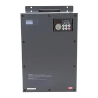
Mitsubishi Electric FR-F740 EC Instruction Manual (680 pages)
FR-F700 Series
Brand:
Mitsubishi Electric
| Category:
Inverter
| Size: 13.88 MB
Table of Contents
Instruction Manual
1
Safety Instructions
5
Table of Contents
13
1 Product Checking and Part Identification
21
Inverter Type
21
Description of the Case
22
Accessory
23
2 Installation
25
Removal and Reinstallation of the Operation Panel
25
Removal and Reinstallation of the Front Cover
26
FR-F740-00023 to 00620-EC
26
FR-F740-00770 to 12120-EC
27
FR-F746-00023 to 01160-EC
29
Mounting
30
Enclosure Design
31
Inverter Installation Environment
31
Inverter Placement
35
Heatsink Protrusion Attachment (FR-A7CN)
37
3 Wiring
39
Inverter and Peripheral Devices
39
Peripheral Devices
41
Terminal Connection Diagram
43
Main Circuit Connection
45
Specification of Main Circuit Terminal
45
Terminal Layout and Wiring
46
Cables and Wiring Length
49
Cable Size
49
Control Circuit Specifications
54
Control Circuit Terminals
59
Wiring Instructions
61
Separate Power Supply for the Control Circuit
62
Changing the Control Logic
65
Connecting the Operation Panel/Parameter Unit Using a Connection Cable
68
RS485 Terminal Block
69
Communication Operation
70
Connection of Stand-Alone Option Units
71
Magnetic Contactors (MC)
71
Connection of a Brake Unit (FR-BU/MT-BU5)
73
Connection of the High Power Factor Converter (FR-HC, MT-HC)
76
Connection of the Power Regeneration Common Converter FR-CV
78
(01160 or Less)
78
Connection of Power Regeneration Converter (MT-RC) (01800 or More)
79
Connection of the Power Improving DC Reactor
80
Installation of a Reactor
81
Electromagnetic Compatibility (EMC)
82
Leakage Currents and Countermeasures
82
Inverter-Generated Noises and Their Reduction Techniques
87
EMC Filter
90
Power Supply Harmonics
91
Inverter-Driven 400V Class Motor
92
4 Operation
93
Precautions for Use of the Inverter
93
Drive the Motor
96
Operation Panel FR-DU07
97
Parts of the Operation Panel
97
Basic Operation (Factory Setting)
99
Easy Operation Mode Setting (Easy Setting Mode)
100
Operation Lock
102
Monitoring of Output Current and Output Voltage
104
First Priority Monitor
104
Digital Dial Push
104
Change the Parameter Setting Value
105
Overheat Protection of the Motor by the Inverter
107
PU Operation Mode
109
Set the Set Frequency to Operate
110
Use the Digital Dial Like a Potentiometer to Perform Operation
111
Use Switches to Give the Frequency Command (Multi-Speed Setting)
112
Perform Frequency Setting by Analog Voltage Input
115
Perform Frequency Setting by Analog Current Input
117
External Operation
119
Use the Set Frequency Set by the Operation Panel (Pr. 79 = 3)
119
Use Switches to Give a Start Command and a Frequency Command (Multi-Speed Setting) (Pr. 4 to Pr. 6)
121
Perform Frequency Setting by Analog Voltage Input
124
Change the Frequency (50Hz) of the Maximum Value of Potentiometer
127
Perform Frequency Setting by Analog Current Input
128
Change the Frequency (50Hz) of the Maximum Value of Potentiometer
130
5 Basic Settings
131
Simple Mode Parameter List
131
Increase the Starting Torque (Pr. 0)
133
Limit the Maximum and Minimum Output Frequency (Pr. 1, Pr. 2)
135
When the Rated Motor Frequency Is 60Hz (Pr. 3)
137
Change the Acceleration/Deceleration Time (Pr. 7, Pr. 8)
138
Energy Saving Operation (Pr. 60)
140
Operation Mode (Pr. 79)
142
Parameter Clear
143
All Parameter Clear
144
Parameter Copy and Parameter Verification
145
Parameter Copy
146
Parameter Verification
148
Initial Value Change List
149
6 Parameter
151
Parameter Overview
151
Motor Torque
189
Manual Torque Boost (Pr. 0, Pr. 46)
189
Simple Magnetic Flux Vector Control (Pr. 80, Pr. 90)
192
Slip Compensation (Pr. 245 to Pr. 247)
193
Stall Prevention
194
Multiple Rating (LD = Light Duty, SLD = Super Light Duty) (Pr. 570)
203
Limit the Output Frequency
204
Maximum and Minimum Frequency (Pr. 1, Pr. 2, Pr. 18)
204
Avoid Mechanical Resonance Points (Frequency Jump)
206
Set V/F Pattern
208
Base Frequency, Voltage (Pr. 3, Pr. 19, Pr. 47)
208
Load Pattern Selection (Pr. 14)
210
Adjustable 5 Points V/F (Pr. 71, Pr. 100 to Pr. 109)
211
Frequency Setting by External Terminals
213
(Pr. 4 to Pr. 6, Pr. 24 to Pr. 27, Pr. 232 to Pr. 239)
213
Multi-Speed Setting Operation
213
Jog Operation (Pr. 15, Pr. 16)
216
Input Compensation of Multi-Speed and Remote Setting (Pr. 28)
220
Remote Setting Function (Pr. 59)
221
Acceleration and Deceleration
225
Acceleration and Deceleration Time
225
Starting Frequency and Start-Time Hold Function (Pr. 13, Pr. 571)
229
Acceleration and Deceleration Pattern (Pr. 29, Pr. 140 to Pr. 143)
231
Selection and Protection of a Motor
235
Motor Protection from Overheat (Electronic Thermal Relay Function)
235
Motor Protection from Overheat (Electronic Thermal Relay Function) (Pr. 9, Pr. 51, Pr. 561, Pr. 986)
235
Applied Motor (Pr. 71)
243
Motor Brake and Stop Operation
244
DC Injection Brake (Pr. 10 to Pr. 12)
244
Selection of a Regenerative Brake and DC Feeding (Pr. 30, Pr. 70)
247
Stop Selection (Pr. 250)
255
Output Stop Function (Pr. 522)
257
Function Assignment of External Terminals
259
Input Terminal Function Selection (Pr. 178 to Pr. 189)
259
Inverter Output Shutoff Signal (MRS Signal, Pr. 17)
262
Operation Condition Selection of Second Function Selection Signal
264
(Terminal RT, Pr. 155)
264
Start Signal Selection (Terminal STF, STR, STOP, Pr. 250)
266
Output Terminal Function Selection (Pr. 190 to Pr. 196)
270
Detection of Output Frequency (SU, FU, FU2, Pr. 41 to Pr. 43, Pr. 50, Pr. 870)
277
Output Current Detection Function (Y12, Y13, Pr. 150 to Pr. 153, Pr. 166, Pr. 167)
280
Remote Output Function (REM, Pr. 495 to Pr. 497)
283
Pulse Train Output of Output Power (Y79 Signal, Pr. 799)
285
Monitor Display and Monitor Output Signals
286
Speed Display and Speed Setting (Pr. 37, Pr. 144, Pr. 505)
286
DU/PU Monitor Display Selection
288
CA, am Terminal Function Selection (Pr. 55, Pr. 56, Pr. 867, Pr. 869)
296
Terminal CA, am Calibration [C0 (Pr. 900), C1 (Pr. 901), C8 (Pr. 930) to C11 (Pr. 931)]
298
Operation Selection at Power Failure
303
Automatic Restart (Pr. 57, Pr. 58, Pr. 162 to Pr. 165, Pr. 299, Pr. 611)
303
Power Failure Signal (Y67 Signal)
311
Power Failure-Time Deceleration-To-Stop Function (Pr. 261 to Pr. 266)
312
Operation Setting at Alarm Occurrence
319
Retry Function (Pr. 65, Pr. 67 to Pr. 69)
319
Alarm Code Output Selection (Pr. 76)
323
Input/Output Phase Loss Protection Selection (Pr. 251, Pr. 872)
325
Energy Saving Operation and Energy Saving Monitor
326
Energy Saving Control and Optimum Excitation Control (Pr. 60)
326
Energy Saving Monitor (Pr. 52, Pr. 54, Pr. 158, Pr. 891 to Pr. 899)
328
Motor Noise, Noise Reduction
335
Speed Smoothing Control (Pr. 653, Pr. 654)
337
Frequency Setting by Analog Input (Terminals 1, 2 and 4)
338
Analog Input Selection (Pr. 73, Pr. 267)
338
Analog Input Compensation (Pr. 73, Pr. 242, Pr. 243, Pr. 252, Pr. 253)
345
Input Filter Time Constant (Pr. 74)
348
Bias and Gain of Frequency Setting Voltage (Current) [Pr. 125, Pr. 126, Pr. 241, C2 (Pr. 902) to C7 (Pr. 905)]
349
4Ma Input Check of Current Input (Pr. 573, Pr. 777, Pr. 778)
357
Misoperation Prevention and Parameter Setting Restriction
363
Reset Selection/Disconnected PU Detection/Pu Stop Selection (Pr. 75)
363
Parameter Write Selection (Pr. 77)
368
Reverse Rotation Prevention Selection (Pr. 78)
370
User Groups (Pr. 160, Pr. 172 to Pr. 174)
371
Password Function (Pr. 296, Pr. 297)
374
Selection of Operation Mode and Operation Location
379
Operation Mode Selection (Pr. 79)
379
Operation Mode at Power on (Pr. 79, Pr. 340)
392
Operation Command Source and Speed Command Source During Communication Operation (Pr. 338, Pr. 339, Pr. 550, Pr. 551)
394
Communication Operation and Setting
402
PU Connector
403
RS485 Terminals
406
Initial Settings and Specifications of RS485 Communication
411
(Pr. 117 to Pr. 124, Pr. 331 to Pr. 337, Pr. 341, Pr. 502, Pr. 549, Pr. 779)
411
Communication E²PROM Write Selection (Pr. 342)
414
Operation Selection at Communication Error (Pr. 502, Pr. 779)
414
Mitsubishi Inverter Protocol (Computer Link Communication)
418
Error Code
424
Modbus-RTU Communication (Pr. 331, Pr. 332, Pr. 334, Pr. 343, Pr. 502, Pr. 539, Pr. 549, Pr. 779)
439
Alarm History
456
Bacnet MS/TP Protocol
460
Analog Output
466
Protocol Implementation Conformance Statement - PICS
476
Operation by PLC Function (Pr. 414, Pr. 415, Pr. 498, Pr. 506 to Pr. 515, Pr. 826 to Pr. 865)
477
PID Control
478
PID Control (Pr. 127 to Pr. 134, Pr. 553, Pr. 554, Pr. 575 to Pr. 577)
478
Bias and Gain Calibration for PID Displayed Value [Pr. 241, Pr. 759, C42 (Pr. 934) to C45 (Pr. 935)]
496
Pre-Charge Function (Pr. 760 to Pr. 769)
500
Second PID Function (Pr. 753 to Pr. 758, Pr. 765 to Pr. 769)
508
Advanced PID Function (Pump Function) (Pr. 554, Pr. 575 to Pr. 591)
511
Special Operation
525
Commercial Power Supply-Inverter Switchover Function
525
(Pr. 57, Pr. 58, Pr. 135 to Pr. 139, Pr. 159)
525
Traverse Function (Pr. 592 to Pr. 597)
533
Regeneration Avoidance Function (Pr. 665, Pr. 882 to Pr. 886)
536
Useful Functions
539
Cooling Fan Operation Selection (Pr. 244)
539
Display of the Life of the Inverter Parts (Pr. 255 to Pr. 259)
540
Maintenance Timer Alarm (Pr. 503, Pr. 504)
544
Current Average Value Monitor Signal (Pr. 555 to Pr. 557)
545
Free Parameters (Pr. 888, Pr. 889)
549
Initiating a Fault (Pr. 997)
550
Setting Multiple Parameters as a Batch (Pr. 999)
552
Setting of Parameter Unit and Operation Panel
558
PU Display Language Selection (Pr. 145)
558
Operation Panel Frequency Setting/Key Lock Operation Selection
559
Buzzer Control (Pr. 990)
559
PU Contrast Adjustment (Pr. 991)
560
Setting of FR-PU07-01
561
PID Display Bias/Gain Setting Menu
562
Unit Selection for the PID Parameter/Pid Monitored Items (Pr. 759)
563
PID Set Point Direct Setting Menu
565
3-Line Monitor Selection (Pr. 774 to Pr.776)
566
7 Troubleshooting
569
List of Alarm Display
570
Causes and Corrective Actions
572
Reset Method of Protective Function
591
LED Display
593
Check and Clear of the Alarm History
594
Check First When You Have Troubles
596
Motor Does Not Start
596
Motor or Machine Is Making Abnormal Acoustic Noise
598
Inverter Generates Abnormal Noise
598
Motor Generates Heat Abnormally
598
Motor Rotates in the Opposite Direction
599
Speed Greatly Differs from the Setting
599
Acceleration/Deceleration Is Not Smooth
599
Speed Varies During Operation
600
Operation Mode Is Not Changed Properly
600
Operation Panel (FR-DU07) Display Is Not Operating
601
Motor Current Is too Large
601
Speed Does Not Accelerate
602
Unable to Write Parameter Setting
603
Power Lamp Is Not Lit
603
Meters and Measuring Methods
604
Measurement of Powers
605
Measurement of Voltages and Use of PT
606
Measurement of Currents
606
Use of CT and Transducer
607
Measurement of Inverter Input Power Factor
607
Measurement of Converter Output Voltage (Across Terminals P/+ and N/-)
607
8 Maintenance and Inspection
609
Inspection
609
Daily Inspection
609
Periodic Inspection
609
Daily and Periodic Inspection
610
Display of the Life of the Inverter Parts
612
Checking the Inverter and Converter Modules
615
Cleaning
616
Replacement of Parts
616
Inverter Replacement
624
Measurements on the Main Circuit
625
Insulation Resistance Test Using Megger
625
Pressure Test
625
Measurement of Voltages and Currents
626
A Appendix
629
Specifications FR-F740-00023 to -01160
629
Specifications FR-F740-01800 to -12120
630
Specifications FR-F746-00023 to -01160
631
Common Specifications
632
Outline Dimension Drawings
634
FR-F740-00023 to -00126
634
FR-F740-00170 to -00380
635
FR-F740-00470 and -00620
636
FR-F740-00770 to -01160
637
Fr-F740-01800
638
FR-F740-02160 to -03610
639
FR-F740-04320 to -06830
640
FR-F740-07700 and -08660
641
FR-F740-09620 to -12120
642
FR-F746-00023 to -00126
643
FR-F746-00170 and -00250
643
FR-F746-00310 and -00380
644
FR-F746-00470 and -00620
644
Fr-F746-00770
645
FR-F746-00930 and -01160
645
DC Reactors
646
Panel Cutting for the Heatsink Protrusion Attachment
648
Operation Panel FR-DU07
649
Parameter Unit FR-PU07
649
Parameter List with Instruction Codes
650
Specification Change
669
SERIAL Number Check
669
Advertisement
Advertisement
Related Products
Mitsubishi Electric FR-F740-00023
Mitsubishi Electric FR-F740P-250K
Mitsubishi Electric FR-F740-30K
Mitsubishi Electric FR-F740-45K
Mitsubishi Electric FR-F740-110K
Mitsubishi Electric FR-F740-450K
Mitsubishi Electric FR-F740-500K
Mitsubishi Electric FR-F740-560K
Mitsubishi Electric FR-F740-00770-NA
Mitsubishi Electric FR-F740PJ-1.5KF
Mitsubishi Electric Categories
Air Conditioner
Controller
Projector
Inverter
Heat Pump
More Mitsubishi Electric Manuals
Login
Sign In
OR
Sign in with Facebook
Sign in with Google
Upload manual
Upload from disk
Upload from URL