Advertisement
FR-F
700 Series
Instruction Manual Supplement
Before using this FR-F746-EC (IP54 specification) inverter, please read through the
following instructions along with the supplied manual for this inverter.
1. Inverter type
Symbol
Voltage/structure specification
Three-phase 400V class/
waterproof structure IP54
F746
(standard IEC 60529:2001)
specification
2. Removal and installation method of the front cover
(1) Removal
• After removing the installation screw, remove the front cover.*
• Remove the connection cable from the PU connector.
• Remove the hook of metal chain end from the inverter.
* Since the metal chain is mounted to the front cover, remove the front cover slowly.
Metal chain
(2) Installation
• Install the hook of metal chain end to the inverter.
• Connect the connection cable to the PU connector.
• Fix the front cover using the installation screws securely.
CAUTION
· When installing the front cover, be careful not to pinch the connection cable or
the metal chain.
FR -
F746
Removal/installation
hook
Connection cable
00126
- EC
-
Symbol
Description
00023
Displays the SLD rated
to
current
00620
1/8
BCN-C22005-352
Advertisement
Table of Contents

Related Manuals for Mitsubishi Electric FR-F746-EC


Summary of Contents for Mitsubishi Electric FR-F746-EC
- Page 1 FR-F 700 Series Instruction Manual Supplement Before using this FR-F746-EC (IP54 specification) inverter, please read through the following instructions along with the supplied manual for this inverter. 1. Inverter type 00126 - EC FR - F746 Symbol Voltage/structure specification Symbol...
- Page 2 3. Precautions for use of the inverter There are following precautions for IP54 specification. (1) Do not remove the operation panel. The operation panel is installed to the front cover. The connection cable is also connected to PU connector internal of the inverter.
- Page 3 (4) The cooling fan fixes the fan cover with fixed screws. For the type, refer to the following table. Inverter Type Fan Type Units 00083,00126 MMF-09D24TS-RP3 BKO-CA1640H03 00170,00250,00310, MMF-09D24TS-RP3 BKO-CA1640H03 00380 F746 00470,00620 MMF-12D24DS-RP3 BKO-CA1619H03 00770 MMF-09D24DS-RP3 BKO-CA1640H03 00930,01160 MMF-12D24DS-RP3 BKO-CA1619H03 *1 The clearances above and under the inverter should be 10cm or more.
- Page 4 4. Rating SLD is initially set. Type FR-F746- 00023 00038 00052 00083 00126 00170 00250 00310 00380 00470 00620 00770 00930 01160 Applied motor capacity 0.75 18.5 (kW) *1 Rated capacity 12.2 17.5 22.1 26.7 32.8 43.4 53.3 64.8 80.8 (kVA) *2 11.5 Rated...
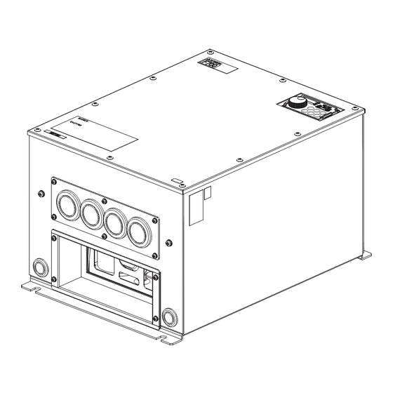
- Page 5 5. Outline dimension drawings •FR-F746-00023,00038,00052,00083,00126-EC Exhaust 2holes 7 Screw : M6 Rating plate 86.5 86.5 (Unit : mm) 3holes 28 (with rubber bushing) explosion-releasing valve •FR-F746-00170,00250-EC Exhaust 2holes 7 Screw : M6 Rating plate (Unit : mm) 87.5 87.5 4holes 35 (with rubber bushing) explosion-releasing valve...
- Page 6 •FR-F746-00310,00380-EC Exhaust 2holes 10 Screw : M8 Rating plate (Unit : mm) 4holes 35 (with rubber bushing) explosion-releasing valve •FR-F746-00470,00620-EC Exhaust 2holes 10 Screw : M8 Rating plate (Unit : mm) 4holes 44 (with rubber bushing) explosion-releasing valve BCN-C22005-352...
- Page 7 •FR-F746-00770-EC Exhaust 2holes 10 Screw : M8 Rating plate (Unit : mm) 55.5 55.5 4holes 63 (with rubber bushing) •FR-F746-00930,01160-EC Exhaust 2holes 12 Screw : M10 Rating plate (Unit : mm) 91.5 91.5 4holes 63 (with rubber bushing) BCN-C22005-352...
- Page 8 MEMO BCN-C22005-352...
Need help?
Do you have a question about the FR-F746-EC and is the answer not in the manual?
Questions and answers