Lutron Electronics GRAFIK Eye QSGRJ-3P Installation And Operation Manual
Grafik eye qs control unit
Hide thumbs
Also See for GRAFIK Eye QSGRJ-3P:
- Installation and operation manual (67 pages) ,
- Programming addendum (8 pages)
Table of Contents
Advertisement
Quick Links
®
Please Read
Model Numbers: QSGRJ-3P, QSGRJ-4P, QSGRJ-6P
QSGR-3P, QSGR-4P, QSGR-6P
Unit Capacity (watts)
MLV
Zone Capacity (watts)
MLV
See page 8 for PELV (Class 2: USA) ratings.
120 V
50/60 Hz
2000 W
2000 VA / 1 600 W
25 – 800 W
25 – 800 VA / 25 – 600 W
LUTRON
220 - 240 V
50/60 Hz
3000 W
3000 VA / 2 400 W
40 – 1200 W
40 – 1200 VA / 40 – 960 W
Installation and
Operation Guide
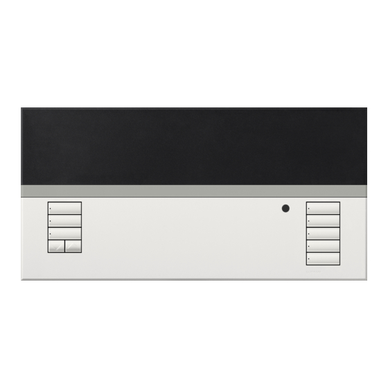
The GRAFIK Eye QS control unit allows
for control of both lights and shades,
without interfaces, using a single control
unit. Features include pushbutton scene
recall, info screen that displays energy
savings and status, IR receiver, astronomic
timeclock, contact closure input, and
engravable backlit buttons that are easy to
find and operate.
Advertisement
Table of Contents
Troubleshooting

Related Manuals for Lutron Electronics GRAFIK Eye QSGRJ-3P


Summary of Contents for Lutron Electronics GRAFIK Eye QSGRJ-3P
-
Page 1: Please Read
IR receiver, astronomic timeclock, contact closure input, and engravable backlit buttons that are easy to find and operate. LUTRON Model Numbers: QSGRJ-3P, QSGRJ-4P, QSGRJ-6P QSGR-3P, QSGR-4P, QSGR-6P 120 V 50/60 Hz 220 - 240 V 50/60 Hz... -
Page 2: Table Of Contents
Contents Features and Functions of the Contact Closure Input (CCI) Mode Setup . . . Associating Sivoia QS Shades/Drapes ® GRAFIK Eye and GRAFIK Eye QS Control Units . . . . . . ®... -
Page 3: Features And Functions Of The Grafik Eye ® Qs
Features and Functions of the GRAFIK Eye ® Hinged faceplate Info screen Zone numbers Displays status or programming functions Zone raise/lower buttons Master buttons Zone LEDs display current lighting zone levels Temporarily raise and lower lighting levels on unit Timeclock button Scene buttons Displays current With integral scene... -
Page 4: Wiring The Grafik Eye
Wiring the GRAFIK Eye ® Overview of Line Voltage/Mains Wiring 1 2 3 4 5 6 L N Line Voltage/Mains 1 2 3 4 5 6 L N Cables and Load Wiring Terminal labels: L: Hot/Live N: Neutral : Ground 1-6: Dimmed/Switched 120 - 127 V line voltage outputs... -
Page 5: Line Voltage Wiring Details
Wiring the GRAFIK Eye QS: Line Voltage Wiring Details ® • Use properly certified cable for all line voltage/mains cables. • Proper short-circuit and overload protection must be provided at the distribution panel. You can use up to a 20 A circuit breaker for your installation. •... - Page 6 Wiring the GRAFIK Eye QS: Line Voltage Wiring Details (continued) ® The recommended installation torque is Step 4: Connect line voltage and loads 5.0 in∙lbs (0.6 N∙m) for line voltage/mains to control unit. connections and 5.0 in∙lbs (0.6 N∙m) for •...
-
Page 7: Overview Of Pelv (Class 2: Usa) Wiring
Wiring the GRAFIK Eye ® Overview of PELV (Class 2: USA) Wiring IR Wiring 18 AWG (1.0 mm each terminal 1: IR DATA From external 2: IR COM IR connection (by others) 1 2 3 4 5 6 L N Contact Closure Input Wiring 1 2 3 4 5 6 L N For settings, see page 21. -
Page 8: Qs Link Control Wiring Details
Wiring the GRAFIK Eye ® QS Link Control Wiring Details • System communication uses PELV (Class 2: USA) System Limits wiring. The QS wired communication link is limited to 100 devices or 100 zones. Please • Follow all local and national electrical codes when note the zone count and power draw unit information in the following table. -
Page 9: Qs Link Control Wiring And Terminal Connection Example
Wiring the GRAFIK Eye ® QS Link Control Wiring and Terminal Connection Example Control units shown in rear view • Connect the terminal 1, 3, and 4 connections to all control units, wallstations, and control interfaces. • Each control unit has its own power supply. -
Page 10: Powering More Than 3 Wallstations
Wiring the GRAFIK Eye ® Powering More Than 3 Wallstations • The GRAFIK Eye QS can power up to • The Common wire from the power supply • The +24 VDC wire from the power supply 3 seeTouch wallstations. An external connects to QS link terminal 1 on all connects to QS link terminal 2 on all of ®... -
Page 11: Completing Installation Of The Grafik Eye Qs
Completing Installation of the GRAFIK Eye ® 7.9 in 1. Mount the control unit in the wallbox as (200 mm) shown using the four screws pro vid ed. Note: Follow all local and national electrical codes when installing PELV 3.5 in (87 mm) (Class 2: USA) wiring with line voltage/ 3.75 in... -
Page 12: General Functionality
General Functionality The info screen turns off 30 seconds after the last button press or completion of the last scene change. See example screens below. The Master buttons activate the info screen. These buttons Scene 1 temporarily raise or lower all dimmable lights (except those programmed as unaffected in the current scene). -
Page 13: Pre-Programmed Button Functionality
Pre-Programmed Button Functionality The GRAFIK Eye QS controls most lighting loads without special programming. Each ® unit ships with pre-programmed default settings for the scene and shade buttons. For load types other than those shown below (dimmable or non-dim), set the load type before proceeding. -
Page 14: Zone Button Operation
Zone Button Operation Each zone column (LEDs and buttons) Zone LEDs represents one zone of lights. Pressing LEDs indicate any button on a column turns on the info light level screen and displays the zone’s current (see below) light level and current energy savings. Zone Raise Pressing the raise and lower buttons on a zone causes different actions depending... -
Page 15: Programming Mode
Programming Mode Entering and Exiting Programming Mode Main menu To enter programming mode: Press and hold the top and bottom scene Timeclock Master buttons buttons simultaneously for 3 seconds. The Scene setup LEDs in the scene buttons will scroll from OK button top to bottom, confirming that you are in programming mode, and the info screen will... -
Page 16: Wireless Mode
• Enabled: The GRAFIK Eye QS Wireless control unit will respond to any programming Changes or modifications not expressly approved by Lutron Electronics Co. could void the user’s commands from nearby Lutron QS wireless (and compatible) products. authority to operate this equipment. -
Page 17: Zone Setup
Zone Setup Assign Load Types Master buttons 1. Enter programming mode (see Main menu page 15). OK button CCI Mode 2. Use the Master buttons to Zone setup highlight “Zone setup” and press the OK button to accept. 3. Use the Master buttons to Use the zone Zone Setup... -
Page 18: Setting Load Types
Zone Setup (continued) Load Type Notes Setting Load Types • All electronic low-voltage (ELV) lighting used with an Direct control via Control via interface must be rated for reverse GRAFIK Eye power module ® phase control dimming. Before installing an ELV light source, Power LUTRON verify with the manufacturer that... -
Page 19: Set High End Or Low End Trim
Zone Setup Set High End or Low End Trim Master • If you are unsure about appropriate high and low end settings, buttons please contact Lutron Technical Support for assistance. • High and low end trim settings limit the maximum and minimum button output of a dimming zone. -
Page 20: Label A Zone (Optional)
Zone Setup Label a Zone (optional) Master 1. Enter programming mode (see page 15). buttons Main menu 2. Use the Master buttons to highlight “Zone setup” and press CCI Mode the OK button to accept. button 3. Use the Master buttons to highlight “Label” and press the Zone setup OK button to accept. -
Page 21: Contact Closure Input (Cci) Mode Setup
Contact Closure Input (CCI) Mode Setup (wired directly to the GRAFIK Eye ® Master The integral contact closure input (CCI) on the back of the GRAFIK Eye QS can ® buttons be configured to match the installation requirements. The choices are listed and explained below. -
Page 22: Associating Wireless Occupancy Sensors And Grafik Eye
Associating Wireless Occupancy Sensors and GRAFIK Eye QS Wireless Control Units ® (for wireless enabled units only) Lutron’s wireless Radio Powr Savr occupancy and vacancy sensors can On the wireless occupancy sensor, press and hold the be associated with the GRAFIK Eye QS Wireless to activate scenes when “Lights On”... -
Page 23: Occupancy Sensor Setup
Occupancy Sensor Setup Mode Assignment This step allows you to assign occupancy sensors (wired and wireless) on the QS link or Master buttons connected to the GRAFIK Eye QS control unit. Sensors can be assigned in either Scene ® Mode or Zone Mode. button Scene Mode (default) is useful when the GRAFIK Eye QS is controlling lights in a single room or area. -
Page 24: Scene Mode
Occupancy Sensor Setup Scene Mode This step allows you to assign occupied and unoccupied scenes to up to four Master buttons occupancy sensors connected to the GRAFIK Eye QS control unit. ® Select Sensors Occ Sensor button 1. If not already done, complete the steps on page 22, and Setup select “Scene Mode”. -
Page 25: Zone Mode
Occupancy Sensor Setup Zone Mode Master This step allows you to assign occupied and unoccupied zone levels to up to four buttons occupancy sensors per zone connected to the GRAFIK Eye QS control unit. Sensors ® can be added to more than one zone. button Select Sensors Occ Sensor... -
Page 26: Label An Occupancy Sensor (Optional)
Occupancy Sensor Setup Label an Occupancy Sensor (optional) Master 1. Enter programming mode (see page 15). Main menu buttons 2. Use the Master buttons to highlight “Sensor Setup” and press Zone Setup the OK button to accept. button Sensor Setup 3. -
Page 27: Configure Occupancy Sensor Settings
Occupancy Sensor Setup Configure Occupancy Sensor Settings Master 1. Enter programming mode (see page 15). Main menu buttons 2. Use the Master buttons to highlight “Sensor Setup” and press Zone Setup the OK button to accept. button Sensor Setup 3. Use the Master buttons to highlight “Occupancy” and press the OK button to accept. -
Page 28: Associating Wireless Daylight Sensors And Grafik Eye
Associating Wireless Daylight Sensors and GRAFIK Eye QS Wireless Control Units ® (for wireless enabled units only) Lutron’s wireless Radio Powr Savr daylight sensors can be associated with the GRAFIK Eye QS Wireless to adjust light levels when certain daylight levels are detected. This section applies to installations where the GRAFIK Eye QS Wireless is being used in Master a single-room wireless installation. -
Page 29: Daylight Sensor Setup
Daylight Sensor Setup Assign Sensors This step allows you to assign sensors to each zone, with one daylight sensor per Master buttons zone connected to the GRAFIK Eye QS control unit. Sensors can be assigned to ® more than one zone. button Select Sensors Daylight Sensor... -
Page 30: Label A Daylight Sensor (Optional)
Daylight Sensor Setup Label a Daylight Sensor (optional) Master 1. Enter programming mode (see page 15). Main menu buttons 2. Use the Master buttons to highlight “Sensor Setup” and press Zone Setup the OK button to accept. button Sensor Setup 3. -
Page 31: Scene Setup
Scene Setup Set Zone Levels, Fade Rates, and Shade Group Actions Master 1. Enter programming mode (see page 15). Main menu buttons 2. Use the Master buttons to highlight “Scene setup” and press Timeclock the OK button to accept. button Scene setup 3. -
Page 32: Label A Scene (Optional)
Scene Setup Label a Scene (optional) Master 1. Enter programming mode (see Main menu buttons page 15). Timeclock 2. Use the Master buttons to highlight button “Scene setup” and press the Scene setup OK button to accept. 3. Use the Master buttons to highlight Scene setup “Labels”... -
Page 33: Set Save Mode
Set Save Mode 1. Enter programming mode (see page 15). Main menu 2. Use the Master buttons to highlight “Save mode” and press Scene setup the OK button to accept. Master Save mode 3. Use the Master buttons to highlight the save mode you would buttons like. -
Page 34: Quick Scene Programming
Quick Scene Programming Save by OK Mode By default, the GRAFIK Eye QS is in ® “Save by OK” mode, which allows you to quickly set scenes without entering program mode. 1. Press the button for the scene you want to set;... -
Page 35: Timeclock Operation
Timeclock Operation Set Time and Date 1. Enter programming mode (see page 15). Master Main menu buttons 2. Use the Master buttons to highlight “Timeclock” and press the Timeclock Timeclock OK button to accept. Scene setup button 3. Use the Master buttons to highlight “Time & date” and press the OK button to accept. -
Page 36: Set Location
Timeclock Operation Set Location 1. Enter programming mode (see page 15). Main menu Master buttons 2. Use the Master buttons to highlight Timeclock Timeclock “Timeclock” and press the OK button to Scene setup button accept. 3. Use the Master buttons to highlight “Location”... -
Page 37: Add An Event
Timeclock Operation Add an Event Main menu 1. Enter programming mode (see page 15). Master buttons 2. Use the Master buttons to highlight “Timeclock” and press the Timeclock Timeclock OK button to accept. Scene setup button 3. Use the Master buttons to highlight “Add events” and press the OK button to accept. -
Page 38: Delete An Event
Timeclock Operation Delete an Event Master 1. Enter programming mode (see page 15). Main menu buttons 2. Use the Master buttons to highlight Timeclock Timeclock “Timeclock” and press the OK button to button Scene setup accept. 3. Use the Master buttons to highlight Timeclock “Delete events”... -
Page 39: Set A Holiday
Timeclock Operation Set a Holiday 1. Enter programming mode (see page Master Timeclock buttons 15). Delete schedule 2. Use the Master buttons to highlight button “Timeclock” and press the OK button Holidays to accept. 3. Use the Master buttons to highlight Holiday “Holidays”... -
Page 40: Copy A Schedule
Timeclock Operation Copy a Schedule 1. Enter programming mode (see page 15). Master Timeclock buttons 2. Use the Master buttons to highlight Delete schedule Copy schedule “Timeclock” and press the OK button to button accept. Delete events 3. Use the Master buttons to highlight “Copy Schedule”... -
Page 41: Afterhours Mode
Timeclock Operation Afterhours Mode Afterhours Mode is an advanced power-saving feature. It allows occupants to manually Master turn on lights, but automatically turns the lights off after a specified amount of time buttons (Delay time). Before turning off, the lights can be set to flash to warn occupants, giving them the opportunity to extend the time until Afterhours Mode is activated by pressing button a button on the GRAFIK Eye QS or on any associated wallstation. -
Page 42: Set Up Afterhours Mode
Timeclock Operation Set Up Afterhours Mode Main menu 1. Enter programming mode (see page 15). Master 2. Use the Master buttons to highlight “Timeclock”, press the buttons Timeclock Timeclock OK button to accept, then use the Master buttons to highlight Scene setup “Afterhours setup”, and press the OK button to accept. -
Page 43: Associating Pico
Associating Pico Wireless Controls and GRAFIK Eye QS Wireless Control Units ® ® When a GRAFIK Eye QS wireless system includes a Pico wireless control, you can use the Pico wireless control as either a scene controller or a zone controller. This page describes using the Pico wireless control as a scene controller;... -
Page 44: Zone Controller
Associating Pico Wireless Controls and GRAFIK Eye QS Wireless Control Units ® ® To use the Pico wireless controller as a zone controller with a GRAFIK Eye QS Wireless control unit: 1. Make sure the wireless mode of the GRAFIK Eye QS control unit is “Enabled” (see page 16). 2. -
Page 45: Associating Sivoia
Associating Sivoia QS Shades/Drapes and GRAFIK Eye QS Control Units ® ® When a GRAFIK Eye QS system consists of Sivoia QS shades (or drapes) and a GRAFIK Eye QS with one or more shade button groups, you can associate the shade button groups on the control unit with the shades so the shade buttons can directly control the shades. -
Page 46: Adjusting Shade Settings
Adjusting Shade Settings (for Wired and Wireless Sivoia QS Shades/Drapes) ® Setting Limits 2. Select the EDU you want to adjust using 7. Repeat steps 2 through 6 to set the open the top button on the shade button and close limits for each shade assigned Note: Entering Limit Setup mode may group. -
Page 47: Preset Adjustment: Simple Method
Adjusting Shade Settings (for Wired and Wireless Sivoia QS Shades/Drapes) ® Preset Adjustment: Simple Method Preset Adjustment: Advanced Method 4. To move an EDU individually to its desired preset setting, select the EDU 1. Use the raise and lower Note: The advanced method for adjusting using the top button on the shade button buttons on the shade presets is needed only if you wish to... -
Page 48: Name A Group Of Shades
Adjusting Shade Settings (for Wired and Wireless Sivoia QS Shades/Drapes) ® Name a Group of Shades Master 1. Enter programming mode (see page 15). Main menu buttons 2. Use the Master buttons to highlight “Shade Labels” and press Zone Setup the OK button to accept. -
Page 49: Associating Multiple Grafik Eye
Associating Multiple GRAFIK Eye QS Control Units ® When there is more than one GRAFIK To associate two GRAFIK Eye QS Eye QS control unit in a system, it is control units: often convenient to associate them so 1. Begin with the GRAFIK Eye QS control On the unit that will “talk”, press that certain functions carry over to other unit that will “talk”... -
Page 50: Diagnostics And Special Settings
Diagnostics and Special Settings Enable/Disable Timeclock The timeclock can be enabled or disabled as desired. Master 1. Enter programming mode (see page 15), Timeclock buttons select “Timeclock,” and select “Enable/ Disable”. Press the OK button to accept. Monday Enabled button 2. -
Page 51: Activate System Accessories
Activate System Accessories Faceplate Removal Language Selection Once your GRAFIK Eye QS control The faceplates may need to be removed The GRAFIK Eye QS is capable of ® ® unit is programmed, you will need to to change the color or to write in zone operating in the following languages: activate any accessories or interfaces labels. -
Page 52: Troubleshooting
Troubleshooting Symptom Possible Causes Remedy Unit does not control loads Circuit breaker is off Switch circuit breaker on Unit does not turn lights on Low zone settings Reprogram scenes to a higher intensity LEDs on front of unit are not ON Miswire Check wiring Circuit breaker is tripping... -
Page 53: Troubleshooting: Wireless Functions
Troubleshooting (continued): Wireless Functions (for wireless enabled units only) Symptom Possible Causes Remedy Cannot associate a wireless device to a unit Unit does not support wireless functionality Verify unit has a model number beginning with QSGRJ or QSGRK Unit in incorrect wireless mode Change wireless mode to “Enabled”... -
Page 54: Troubleshooting: Shade Functions
Troubleshooting (continued): Shade Functions Symptom Possible Causes Remedy EDU (electronic drive unit of the shade) will not EDU is not powered Check EDU power move Shade fabric is caught on something Check and unbind shade fabric EDU is not assigned to a shade button group Assign the EDU to a shade button group EDU (electronic drive unit of the shade) does not Presets have been set incorrectly... -
Page 55: Warranty
Contact Information Warranty Lutron Electronics Co., Inc. DAMAGES FOR LOSS OF PROFITS, CONFIDENTIAL OR OTHER Internet: www.lutron.com One Year Limited Warranty INFORMATION, OR PRIVACY; BUSINESS INTERRUPTION; E-mail: product@lutron.com For a period of one year from the date of purchase, and subject PERSONAL INJURY; FAILURE TO MEET ANY DUTY, INCLUDING to the exclusions and restrictions described below, Lutron warrants OF GOOD FAITH OR OF REASONABLE CARE; NEGLIGENCE, OR WORLD HEADQUARTERS each new unit to be free from manufacturing defects. Lutron will, ANY OTHER PECUNIARY OR OTHER LOSS WHATSOEVER), NOR at its option, either repair the defective unit or issue a credit equal FOR ANY REPAIR WORK UNDERTAKEN WITHOUT LUTRON’S Lutron Electronics Co., Inc. to the purchase price of the defective unit to the Customer against WRITTEN CONSENT ARISING OUT OF OR IN ANY WAY RELATED the purchase price of comparable replacement part purchased TO THE INSTALLATION, DEINSTALLATION, USE OF OR INABILITY 7200 Suter Road, Coopersburg, PA 18036-1299 from Lutron. Replacements for the unit provided by Lutron or, at its...
Need help?
Do you have a question about the GRAFIK Eye QSGRJ-3P and is the answer not in the manual?
Questions and answers