Lutron Electronics QSGRJ-3P Installation And Operation Manual
Grafik eye qs control unit
Hide thumbs
Also See for QSGRJ-3P:
- Installation and operation manual (55 pages) ,
- Programming addendum (8 pages)
Table of Contents
Advertisement
®
Please Read
Model Numbers: QSGRJ-3P, QSGRJ-4P, QSGRJ-6P
QSGR-3P, QSGR-4P, QSGR-6P
Unit Capacity (watts)
MLV
Zone Capacity (watts)
MLV
See page 7 for IEC PELV/NEC
English
Español
Control Unit
Installation and Operation Guide
120 V~ 50/60 Hz
2000 W
2000 VA / 1600 W
25 – 800 W
25 – 800 VA / 25 – 600 W
Class 2 ratings.
®
Français
The GRAFIK Eye
control of both lights and shades, without
interfaces, using a single control unit.
Features include pushbutton scene recall,
info screen that displays energy savings and
status, IR receiver, astronomic timeclock,
contact closure input, and engravable
backlit buttons that are easy to find and
operate.
LUTRON
220 - 240 V~ 50/60 Hz
3000 W
3000 VA / 2400 W
40 – 1200 W
40 – 1200 VA / 40 – 960 W
QS control unit allows for
®
For California residents only:
The batteries in these devices contain
Perchlorate Material – special handling may apply.
For more information visit
www.dtsc.ca.gov/hazardouswaste/perchlorate
Advertisement
Table of Contents
Troubleshooting

Subscribe to Our Youtube Channel
Related Manuals for Lutron Electronics QSGRJ-3P


Summary of Contents for Lutron Electronics QSGRJ-3P
- Page 1 IR receiver, astronomic timeclock, contact closure input, and engravable backlit buttons that are easy to find and operate. LUTRON Model Numbers: QSGRJ-3P, QSGRJ-4P, QSGRJ-6P QSGR-3P, QSGR-4P, QSGR-6P 120 V~ 50/60 Hz 220 - 240 V~ 50/60 Hz Unit Capacity (watts)
-
Page 2: Table Of Contents
Contents Features and Functions of the Contact Closure Input (CCI) Setup..Timeclock Operation Setting Time and Date ..... 52 GRAFIK Eye QS Control Unit . -
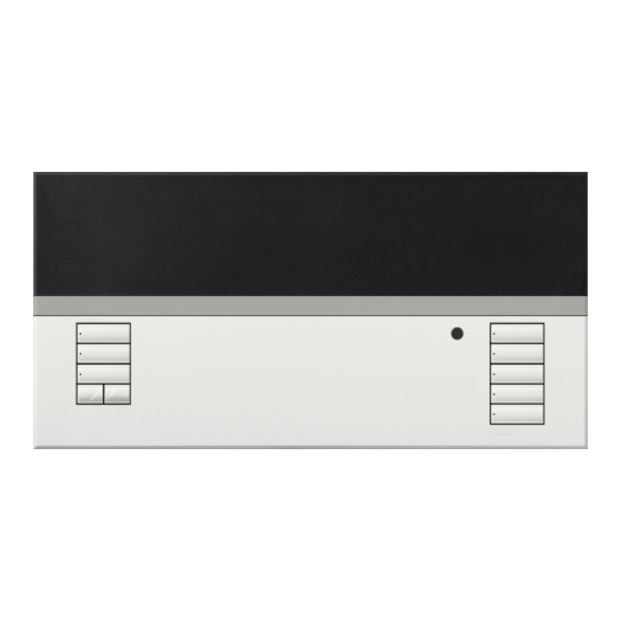
Page 3: Features And Functions Of The Grafik Eye
Features and Functions of the GRAFIK Eye QS Control Unit ® Hinged faceplate Info screen Displays status or programming functions Master buttons Temporarily raise and lower lighting levels on unit Zone numbers “OK” button Zone raise/lower buttons Used for programming Zone LEDs display current lighting zone levels Timeclock button... -
Page 4: Wiring The Grafik Eye
Wiring the GRAFIK Eye QS Control Unit ® Overview of Line Voltage/Mains Wiring 1 2 3 4 5 6 L N Line Voltage/Mains 1 2 3 4 5 6 L N Cables and Load Wiring Terminal labels: L: Hot/Live N: Neutral : Ground 1-6: Dimmed/Switched line voltage outputs... -
Page 5: Line Voltage Wiring Details
Wiring the GRAFIK Eye QS Control Unit (continued) ® Line Voltage Wiring Details • Use properly certified cable for all line voltage/mains cables. • Proper short-circuit and overload protection must be provided at the distribution panel. You can use up to a 20 A circuit breaker for your installation. - Page 6 Wiring the GRAFIK Eye QS Control Unit (continued) ® Line Voltage Wiring Details The recommended installation torque is Step 4: Connect line voltage and loads 5.0 in∙lb (0.6 N∙m) for line voltage/mains to control unit. connections and 5.0 in∙lb (0.6 N∙m) for •...
-
Page 7: Overview Of Iec Pelv/Nec Class 2 Wiring
Wiring the GRAFIK Eye QS Control Unit (continued) ® Overview of IEC PELV/NEC Class 2 Wiring ® IR Wiring 18 AWG (1.0 mm each terminal 1: IR DATA From external 2: IR COM IR connection (by others) 1 2 3 4 5 6 L N Contact Closure Input Wiring 24 V- 50 mA For settings, see CCI Mode Setup. -
Page 8: Qs Link Control Wiring Details
Wiring the GRAFIK Eye QS Control Unit (continued) ® QS Link Control Wiring Details T-Tap Wiring Example • System communication uses IEC PELV/NEC ® Class 2 wiring. • Follow all local and national electrical codes when seeTouch GRAFIK Eye ® ®... -
Page 9: Powering More Than 3 Wallstations Example
Wiring the GRAFIK Eye QS Control Unit (continued) ® Powering More Than 3 Wallstations Example The GRAFIK Eye QS control unit can power up to 3 seeTouch wallstations. An external 24 V- power supply is required to power ® ® more than 3 wallstations. -
Page 10: Completing Installation Of The Grafik Eye
Completing Installation of the GRAFIK Eye QS Control Unit ® 7.9 in 1. Mount the control unit in the wallbox as (200 mm) shown using the four screws pro vid ed. Note: Follow all local and national electrical codes when installing IEC 3.5 in (87 mm) PELV/NEC... -
Page 11: General Functionality
General Functionality The info screen turns off 30 seconds after the last button press or completion of the last scene change. See example screens below. The Master buttons activate the info screen. These buttons Scene 1 Master buttons temporarily raise or lower all dimmable lights (except those programmed as unaffected in the current scene). -
Page 12: Pre-Programmed Button Functionality
Pre-Programmed Button Functionality The GRAFIK Eye QS control unit controls most lighting loads without special ® programming. Each unit ships with pre-programmed default settings for the scene and shade buttons. For load types other than those shown below (dimmable or non-dim), assign the load type before proceeding. -
Page 13: Zone Button Operation
Zone Button Operation Each zone column (LEDs and buttons) Zone LEDs represents one zone of lights. Pressing LEDs indicate any button on a column turns on the info light level screen and displays the zone’s current (see below) light level and current energy savings. Zone Raise Pressing the raise and lower buttons on a zone causes different actions depending... -
Page 14: Programming Mode
Programming Mode Entering and Exiting Programming Mode Entering programming mode: Main menu Press and hold the top and bottom scene Timeclock Master buttons buttons simultaneously for 3 seconds. The Scene setup LEDs in the scene buttons will scroll from “OK” button top to bottom, confirming that you are in programming mode, and the info screen will Timeclock (back) button... -
Page 15: Wireless Mode
FCC Information ® respond to normal operation commands from wireless devices associated while in Changes or modifications not expressly approved by Lutron Electronics Co. could void the user’s “Enabled” mode. authority to operate this equipment. • Disabled: Use for wired-only systems. -
Page 16: Zone Setup
Zone Setup Assigning Load Types Master buttons 1. Enter programming mode. Main menu “OK” button 2. Use the Master buttons to highlight CCI Setup “Zone setup” and press the Zone setup “OK” button to accept. 3. Use the Master buttons to highlight Use the “Load type.”... -
Page 17: Setting Load Types
Zone Setup (continued) Load Type Notes Setting Load Types • All electronic low-voltage (ELV) lighting used with an Direct control via Control via interface must be rated for reverse GRAFIK Eye power module or ® phase control dimming. Before control unit interface installing an ELV light source, Power... -
Page 18: Setting High End Or Low End Trim
Zone Setup (continued) Setting High End or Low End Trim Master • If you are unsure about appropriate high and low end settings, buttons please contact LutronR Technical Support for assistance. “OK” • High and low end trim settings limit the maximum and minimum button output of a dimming zone. -
Page 19: Labeling A Zone (Optional)
Zone Setup (continued) Labeling a Zone (optional) Master 1. Enter programming mode. buttons Main menu 2. Use the Master buttons to highlight “Zone setup” and press “OK” CCI Setup the “OK” button to accept. button 3. Use the Master buttons to highlight “Label” and press the Zone setup “OK”... -
Page 20: Scene Setup
Scene Setup Setting Zone Levels, Fade Rates, and Shade Group Actions Master 1. Enter programming mode. Main menu buttons 2. Use the Master buttons to highlight “Scene setup” and press Timeclock “OK” the “OK” button to accept. button Scene setup 3. -
Page 21: Labeling A Scene (Optional)
Scene Setup (continued) Labeling a Scene (optional) Master 1. Enter programming mode. Main menu buttons 2. Use the Master buttons to highlight “OK” Timeclock “Scene setup” and press the button Scene setup “OK” button to accept. 3. Use the Master buttons to highlight “Labels”... -
Page 22: Setting Save Mode
Setting Save Mode The Save Mode of the GRAFIK Eye QS control unit can be adjusted to turn quick ® scene programming on and off, or to disable the use of zone and/or scene buttons for specific applications. Master Main menu Save Mode Settings buttons Save by OK (default): Quick scene programming mode;... -
Page 23: Contact Closure Input (Cci) Setup
Contact Closure Input (CCI) Setup (wired directly to the GRAFIK Eye QS control unit) ® The integral contact closure input (CCI) on the back of the GRAFIK Eye QS control Master ® buttons unit can be configured as: “OK” Occupancy (default): Allows a wired occupancy sensor to be included in the list of button available sensors when setting up occupancy actions. - Page 24 Contact Closure Input (CCI) Setup (continued) (wired directly to the GRAFIK Eye QS control unit) ® The integral contact closure input (CCI) on the back of the GRAFIK Eye QS control unit Master ® buttons is compatible with either type of contact closure device: “OK”...
-
Page 25: Occupancy Sensor Setup
Occupancy Sensor Setup Lutron occupancy and vacancy sensors work with the GRAFIK Eye QS Wireless control unit to automatically adjust light levels ® ® when occupancy or vacancy is detected. Wired occupancy and vacancy sensors may be connected to the contact closure input on the GRAFIK Eye QS control unit, a QS ®... -
Page 26: Associating Wireless Occupancy Sensors
Occupancy Sensor Setup (continued) Associating wireless occupancy sensors and GRAFIK Eye QS Wireless control units ® (for wireless enabled units only): 1. Make sure the wireless mode of the GRAFIK Eye QS control ® Main menu Master unit is “Enabled.” buttons 9-16 Zone Setup... -
Page 27: Selecting The Mode
Occupancy Sensor Setup (continued) When the GRAFIK Eye QS system is first powered up, occupancy sensors connected ® to the contact closure input (and the first three associated wireless Radio Powr Savr Master buttons occupancy sensors) will automatically operate in “Scene Mode.” Their defaults will be “No Action”... -
Page 28: Scene Mode
Occupancy Sensor Setup (continued) Scene Mode This step allows you to assign up to 16* occupancy sensors to the GRAFIK Eye Master ® buttons control unit. “OK” Selecting Sensors Occ Sensor button 1. If not already done, associate occupancy sensors and set to Setup “Scene Mode.”... -
Page 29: Zone Mode
Occupancy Sensor Setup (continued) Zone Mode Master This step allows you to assign up to four occupancy sensors per zone to the GRAFIK buttons QS control unit. Sensors can be added to more than one zone. ® “OK” Selecting Sensors Occ Sensor button 1. -
Page 30: Labeling An Occupancy Sensor (Optional)
Occupancy Sensor Setup (continued) Labeling an Occupancy Sensor (optional) 1. Enter programming mode. Master Main menu buttons 2. Use the Master buttons to highlight “Sensor Setup” and press Zone Setup the “OK” button to accept. “OK” button Sensor Setup 3. Use the Master buttons to highlight “Occupancy” and press the “OK”... -
Page 31: Configuring Occupancy Sensor Settings (Optional)
Occupancy Sensor Setup (continued) Configuring Occupancy Sensor Settings (optional) Master Occupancy Sensor Settings Main menu buttons Note: These settings affect all sensors assigned to the Zone Setup “OK” GRAFIK Eye QS control unit. ® button Sensor Setup Grace Period: If the GRAFIK Eye QS control unit is ®... -
Page 32: Daylight Sensor Setup
Daylight Sensor Setup Lutron daylight sensors work with the GRAFIK Eye QS Wireless control unit to automatically adjust electric light levels when natural ® ® light in the room changes. Wired daylight sensors may be connected to a QS Sensor Module (QSM) in the QS system. QS Link LUTRON Wired... -
Page 33: Associating Wireless Daylight Sensors
Daylight Sensor Setup (continued) Associating wireless daylight sensors and GRAFIK Eye QS Wireless control units ® (for wireless enabled units only): 1. Make sure the wireless mode of the GRAFIK Eye QS control ® Main menu Master unit is “Enabled.” buttons Zone Setup 2. -
Page 34: Assigning Sensors
Daylight Sensor Setup (continued) This step allows you to assign sensors to zones on the GRAFIK Eye QS control unit. ® Each zone can be assigned to only one sensor, but sensors can be assigned to more Master buttons than one zone. “OK”... -
Page 35: Labeling A Daylight Sensor (Optional)
Daylight Sensor Setup (continued) Labeling a Daylight Sensor (optional) Master 1. Enter programming mode. Main menu buttons 2. Use the Master buttons to highlight “Sensor Setup” and press “OK” Zone Setup the “OK” button to accept. button Sensor Setup 3. Use the Master buttons to highlight “Daylight” and press the “OK”... -
Page 36: Pico Wireless Control Setup
Pico Wireless Control Setup ® LutronR Pico wireless controls can be associated with a GRAFIK Eye QS system to control the light level of a specific zone or to act ® ® as a scene controller. Pico wireless controls can be associated directly to GRAFIK Eye QS Wireless control units, or to a wired or ®... -
Page 37: Wireless Control Unit
Pico Wireless Control Setup (continued) ® Associating the Pico wireless control with a GRAFIK Eye QS Wireless control unit: ® ® (for wireless enabled GRAFIK Eye QS control units only) ® 1. Make sure the wireless mode of the GRAFIK Eye QS control unit is Pico ®... -
Page 38: Associating Through A Qs Sensor Module
Pico Wireless Control Setup (continued) ® Associating the Pico wireless control through a QS Sensor Module (QSM): ® (for wired or wireless enabled GRAFIK Eye QS control units) ® Press and hold the “Program” button on the QSM for 3 seconds to enter programming mode. -
Page 39: Ir Setup
IR Setup An infrared (IR) remote can directly control the GRAFIK Eye QS control unit through ® the infrared receiver on the front of the GRAFIK Eye QS control unit. ® Remote LUTRON GRAFIK Eye ® control unit An externally powered IR repeater can also be connected to the IR terminals on the GRAFIK Eye QS control unit to obtain IR remote control. -
Page 40: Enabling/Disabling The Ir Receiver
IR Setup (continued) Enabling/disabling the IR receiver on the GRAFIK Eye QS control unit: ® Note: These steps will also enable or disable the IR terminals on the Main menu GRAFIK Eye QS control unit. ® Master 1. Enter programming mode. Wireless Mode buttons 2. -
Page 41: Associating The Qs Ir Eye With A Grafik Eye ® Qs Control Unit
IR Setup (continued) The QS IR Eye offers advanced programmable scene control depending on the IR remote being used. Use the chart below to select the appropriate control mode on the GRAFIK Eye QS control unit: ® IR Remote Control Mode Master GRX-IT 4 Buttons &... - Page 42 IR Setup (continued) Associating the QS IR Eye with a GRAFIK Eye QS control unit (continued): ® Note: For use with Lutron remote models MIR-ITFS and C-FLRC. IR Eye ® Point the IR remote at the QS IR Eye. To enter programming mode, press Master Change type? and hold the “On”...
-
Page 43: Associating Through A Qs Sensor Module
IR Setup (continued) Associating IR receivers through a QS Sensor Module (QSM): Upon power up, the QSM will automatically detect and Main menu configure wired IR receivers after a valid signal is received. Master buttons Wireless Mode Use an IR remote to send a signal to all connected receivers in the system. -
Page 44: Associating Sivoia
Associating Sivoia QS Shades/Drapes and GRAFIK Eye QS Control Units ® ® When a GRAFIK Eye QS system consists of Sivoia QS shades (or drapes) and a GRAFIK Eye QS with ® ® ® one or more shade button groups, you can associate the shade button groups on the control unit with the shades so the shade buttons can directly control the shades. -
Page 45: Adjusting Shade Settings
Adjusting Shade Settings (for Wired and Wireless Sivoia QS Shades/Drapes) ® Setting Limits 2. Select the EDU you want to adjust using 7. Repeat steps 2 through 6 to set the open (for wired shades/drapes only) the top button on the shade button and close limits for each shade assigned group. -
Page 46: Preset Adjustment: Simple Method
Adjusting Shade Settings (continued) (for Wired and Wireless Sivoia QS Shades/Drapes) ® Preset Adjustment: Simple Method Preset Adjustment: Advanced Method 3. Use the raise and lower buttons to move all EDUs for assigned shades together to 1. Use the raise and lower buttons on the •... -
Page 47: Naming A Group Of Shades
Adjusting Shade Settings (continued) (for Wired Window Treatments) Naming a Group of Shades 1. Enter programming mode. Main menu 2. Use the Master buttons to highlight “Shade Setup” and press Sensor Setup the “OK” button to accept.* Master buttons Shade Setup 3. -
Page 48: Enable/Disable "Stop If Moving" Functionality
Adjusting Shade Settings (continued) (for Wired Window Treatments) Enable/Disable “Stop If Moving” Functionality (software revision 9.003 or higher) If the GRAFIK Eye QS control unit can be configured to enable/disable the “Stop If ® Moving” functionality: pressing shade column button stops the shade if it is already moving, otherwise the shade is sent to the programmed level. -
Page 49: Associating Sivoia Qs Triathlon Shades With Grafik Eye Qs Control Unit
Associating Sivoia QS Triathlon Shades with GRAFIK Eye QS Control Unit ® ® ® Confirm Wireless Mode Enabled 2. Use the Master Associate Shades Main menu buttons to highlight 1. Enter Programming mode: Press and 1. Tap the Shade button on the shade to Shade labels “Wireless Mode”... -
Page 50: Setting Upper And Lower Limits Of A Sivoia
Setting Upper and Lower Limits of a Sivoia QS Triathlon Shade ® ® with GRAFIK Eye QS Control Unit ® 1. Verify that the shade is associated with 4. Use the Raise/Lower buttons to position 7. Use the Raise/Lower buttons to position the intended Shade button group of the the shade at the desired level for the the shade at the desired level for the... -
Page 51: Associating Multiple Grafik Eye
Associating Multiple GRAFIK Eye QS Control Units ® When there is more than one GRAFIK To associate two GRAFIK Eye ® QS control unit in a system, it is control units: ® often convenient to associate them so 1. Begin with the GRAFIK Eye QS control ®... -
Page 52: Timeclock Operation
Timeclock Operation Setting Time and Date Master Main menu 1. Enter programming mode. buttons 2. Use the Master buttons to highlight “Timeclock” and press the Timeclock Timeclock “OK” “OK” button to accept. button Scene setup 3. Use the Master buttons to highlight “Time & date” and press the “OK”... -
Page 53: Setting Location
Timeclock Operation (continued) Setting Location Main menu 1. Enter programming mode. Master buttons 2. Use the Master buttons to highlight Timeclock Timeclock “Timeclock” and press the “OK” button “OK” Scene setup button to accept. 3. Use the Master buttons to highlight “Location”... -
Page 54: Adding An Event
Timeclock Operation (continued) Adding an Event Main menu Master 1. Enter programming mode. buttons 2. Use the Master buttons to highlight “Timeclock” and press Timeclock Timeclock “OK” the “OK” button to accept. button Scene setup 3. Use the Master buttons to highlight “Add events” and press the “OK”... -
Page 55: Deleting An Event
Timeclock Operation (continued) Deleting an Event Master 1. Enter programming mode. Main menu buttons 2. Use the Master buttons to highlight Timeclock Timeclock “OK” “Timeclock” and press the “OK” button button Scene setup to accept. 3. Use the Master buttons to highlight Timeclock “Delete events”... -
Page 56: Setting A Holiday
Timeclock Operation (continued) Setting a Holiday 1. Enter programming mode. Master Timeclock buttons 2. Use the Master buttons to highlight Delete schedule “Timeclock” and press the “OK” button “OK” button Holiday to accept. 3. Use the Master buttons to highlight “Holiday”... -
Page 57: Copying A Schedule
Timeclock Operation (continued) Copying a Schedule 1. Enter programming mode. Master Timeclock buttons 2. Use the Master buttons to highlight Delete schedule Copy schedule “Timeclock” and press the “OK” button “OK” button to accept. Delete events 3. Use the Master buttons to highlight “Copy Schedule”... -
Page 58: Afterhours
Afterhours The Afterhours feature of the GRAFIK Eye QS control unit can be used to automatically set lights to an energy-saving level (typically ® “Scene Off”). This feature allows occupants to manually turn on lights, but will automatically turn them off after a specified amount of time. -
Page 59: Afterhours Examples
Afterhours (continued) Afterhours Examples Afterhours starts; Afterhours ends Lights flash Example 1: Typical Office Delay to off Afterhours Scene Example 2: Late Night at Office Delay to off Delay to flash Delay to off Afterhours Scene (lights flash) Button press: Office worker Example 3: Late Night/Security Check Delay to off... -
Page 60: Setting Up Afterhours
Afterhours (continued) Setting Up Afterhours 1. Enter programming mode. Main menu Master 2. Use the Master buttons to highlight “Timeclock,” and press buttons Timeclock Timeclock the “OK” button to accept. “OK” Scene setup 3. Use the Master buttons to highlight “Afterhours setup,” and button press the “OK”... -
Page 61: Diagnostics And Special Settings
Diagnostics and Special Settings Enabling/Disabling the Timeclock The timeclock can be enabled or disabled as desired. Master 1. Enter programming mode. Use the Master Timeclock buttons buttons to select “Timeclock.” Press the “OK” “OK” button to accept. Monday button Enabled 2. -
Page 62: Setting The Security Password
Diagnostics and Special Settings (continued) Setting the Security Password A four-digit password can be set as a security feature to protect the Master programming settings on the GRAFIK Eye QS control unit. ® buttons 1. Enter programming mode Diagnostics “OK” 2. -
Page 63: Language Selection
Faceplate Removal Language Selection The faceplates may need to be removed to change the color The GRAFIK Eye QS control unit is ® or to write in zone labels. To remove either faceplate, open it capable of operating in the following fully (flush to the wall), and pull up (for the top faceplate) or languages: down (for the bottom faceplate) to pull the hinges out of their... -
Page 64: Troubleshooting
Troubleshooting Symptom Possible Causes Solution Unit does not power up Circuit Breaker is off Switch circuit breaker on Unit does not control loads Miswire Verify wiring to unit and loads Circuit breaker is tripping System short circuited Find and correct shorts System overload Verify zone/unit loading is within ratings (see Zone Setup section) Zone control does not work... -
Page 65: Troubleshooting: Wireless Functions
Troubleshooting (continued) Symptom Possible Causes Solution Device does not respond to IR Receiver is disabled Enable the IR receiver infrared controls Miswire or loose connection on rear IR terminal Verify rear IR terminal wiring Security lockout from Security password set incorrectly Call LutronR Technical Support to reset password programming mode Troubleshooting: Wireless Functions... -
Page 66: Troubleshooting: Shade Functions
Troubleshooting: Shade Functions Symptom Possible Causes Solution Shade EDU (electronic drive EDU is not powered Connect power to EDU unit) will not move Shade fabric is caught on something Check and unbind shade fabric EDU is not assigned to a shade button group Assign the EDU to a shade button group Shade button group will not All limits are set to the same height... -
Page 67: Warranty
MATERIALS PROVIDED BY LUTRON, IT DOES NOT FORM A Lutron Electron ics Co., Inc. PART OF THE BASIS OF ANY BARGAIN BETWEEN LUTRON AND © 2015 Lutron Electronics Co., Inc. CUSTOMER AND WILL NOT IN ANY WAY BE ENFORCEABLE BY CUSTOMER.
Need help?
Do you have a question about the QSGRJ-3P and is the answer not in the manual?
Questions and answers