Table of Contents
Advertisement
®
Please Read
Model Numbers: QSGR-3PCE, QSGR-4PCE, QSGR-6PCE
QSGRK-3PCE, QSGRK-4PCE, QSGRK-6PCE
QSGRM-3PCE, QSGRM-4PCE, QSGRM-6PCE
QSGRN-6PCE, QSGRQ-6PCE
All units 230 V
50/60 Hz
Unit Capacity (watts)
MLV
Zone Capacity (watts)
MLV
See page 8 for IEC PELV/NEC
Control Unit
Installation and Operation Guide
QSGR-3PCE
QSGRK-3PCE
QSGRM-3PCE
1 500 W
1 500 VA / 1 200 W
40 – 500 W
40 – 500 VA / 40 – 400 W
Class 2 ratings.
®
The GRAFIK Eye
for control of both lights and window
treatments, without interfaces, using
a single control unit. Features include
pushbutton scene recall, info screen
that displays energy savings and status,
IR receiver, astronomic timeclock, contact
closure input, and engravable backlit
buttons that are easy to find and operate.
LUTRON
QSGR-4PCE
QSGRK-4PCE
QSGRM-4PCE
2 000 W
2 000 VA / 1 600 W
40 – 500 W
40 – 500 VA / 40 – 400 W
QS control unit allows
®
QSGR-6PCE
QSGRK-6PCE
QSGRM-6PCE
QSGRN-6PCE
QSGRQ-6PCE
2 300 W
2 300 VA / 1 800 W
40 – 500 W
40 – 500 VA / 40 – 400 W
Advertisement
Table of Contents
Troubleshooting

Related Manuals for Lutron Electronics GRAFIK Eye QSGRN-6PCE


Summary of Contents for Lutron Electronics GRAFIK Eye QSGRN-6PCE
- Page 1 ® Control Unit Installation and Operation Guide Please Read The GRAFIK Eye QS control unit allows ® for control of both lights and window treatments, without interfaces, using a single control unit. Features include pushbutton scene recall, info screen that displays energy savings and status, IR receiver, astronomic timeclock, contact closure input, and engravable backlit buttons that are easy to find and operate.
-
Page 2: Table Of Contents
Contents Features and Functions of the Contact Closure Input (CCI) Setup Timeclock Operation GRAFIK Eye QS Control Unit CCI Mode Settings . . . . . . . . . . . . . . . . . . . . . . . . 24 Setting Time and Date . -
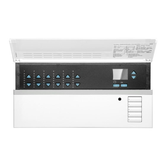
Page 3: Features And Functions Of The Grafik Eye ® Qs Control Unit
Features and Functions of the GRAFIK Eye QS Control Unit ® Hinged faceplate Info screen Zone numbers Displays status or programming functions Zone raise/lower buttons Master buttons Zone LEDs display current lighting zone levels Temporarily raise and lower lighting levels on unit Timeclock button Scene buttons Displays current... -
Page 4: Wiring The Grafik Eye
Wiring the GRAFIK Eye QS Control Unit: ® Overview of Line Voltage/Mains Wiring 1 2 3 4 5 6 L N Line Voltage/Mains 1 2 3 4 5 6 L N Cables and Load Wiring Terminal labels: L: Hot/Live N: Neutral : Ground 1-6: Dimmed/Switched line voltage outputs... -
Page 5: Line Voltage Wiring Details
Wiring the GRAFIK Eye QS Control Unit: ® Line Voltage Wiring Details • Use properly certified cable for all line voltage/mains cables. • Proper short-circuit and overload protection must be provided at the distribution panel. You can use up to a 20 A circuit breaker for your installation. • Install in accordance with all local and national electrical codes. - Page 6 Wiring the GRAFIK Eye QS Control Unit: ® Line Voltage Wiring Details (continued) The recommended installation torque Step 4: Connect line voltage and loads to control unit. is 0.6 N∙m for line voltage/mains connections and 0.6 N∙m for the earth/ • Strip 8 mm of insulation off the line ground connection. voltage/mains cables in the wallbox. Note: See the zone setup section for a list of compatible load types and instructions for programming the...
-
Page 7: Overview Of Iec Pelv/Nec ® Class 2 Wiring
Wiring the GRAFIK Eye QS Control Unit: ® Overview of IEC PELV/NEC Class 2 Wiring ® IR Wiring 1.0 mm each terminal 1: IR DATA From external 2: IR COM IR connection (by others) 1 2 3 4 5 6 L N 1 2 3 4 5 6 L N Contact Closure Input Wiring 24 V... -
Page 8: Qs Link Control Wiring Details
Wiring the GRAFIK Eye QS Control Unit: ® LUTRON LUTRON LUTRON LUTRON QS Link Control Wiring Details LUTRON LUTRON LUTRON T-Tap Wiring Example • System communication uses IEC PELV/NEC ® Class 2 wiring. • Follow all local and national electrical codes when seeTouch ® installing IEC PELV/NEC Class 2 wiring with line ® wallstation GRAFIK Eye ®... -
Page 9: Power Group Wiring Example
Wiring the GRAFIK Eye QS Control Unit: ® Power Group Wiring Example On the QS link, there are devices that supply power and devices that consume power. Each device has a specific number of Power Draw Units (PDUs) it either supplies or consumes. A Power Group consists of one device that supplies power and one or more devices that consume power; each Power Group may have only one power-supplying device. Refer to the QS Link Power Draw Units specification submittal (Lutron PN 369405) for more information concerning PDUs. -
Page 10: Powering More Than 3 Wallstations Example
Wiring the GRAFIK Eye QS Control Unit: ® Powering More Than 3 Wallstations Example The GRAFIK Eye QS control unit can power up to 3 seeTouch wallstations. An external 24 V power supply is required to power ® ® more than three wallstations. • The Common wire from the power • The communication signals on the QS • The +24 VDC wire from the power supply... -
Page 11: Completing Installation Of The Grafik Eye
Completing Installation of the GRAFIK Eye QS Control Unit ® 1. Mount the control unit in the wallbox as 200 mm shown using the four screws pro vid ed. Note: Follow all local and national electrical codes when installing IEC 87 mm PELV/NEC Class 2 wiring with line... -
Page 12: General Functionality
General Functionality The info screen turns off 30 seconds after the last button press or completion of the last scene change. See example screens below. The Master buttons activate the info screen. These buttons Scene 1 Master buttons temporarily raise or lower all dimmable lights (except those programmed as unaffected in the current scene). -
Page 13: Pre-Programmed Button Functionality
Pre-Programmed Button Functionality The GRAFIK Eye QS control unit controls most lighting loads without special ® programming. Each unit ships with pre-programmed default settings for the scene and shade buttons. For load types other than those shown below (dimmable or non-dim), assign the load type before proceeding. See the scene setup section for instructions on changing scene settings. 9-16 Scene Button Pre-Programming for Dimmable Loads Scene 1: All zones to 100% Scene 2: All zones to 75% Scene 3: All zones to 50%... -
Page 14: Zone Button Operation
Zone Button Operation Each zone column (LEDs and buttons) Zone LEDs represents one zone of lights. Pressing LEDs indicate any button on a column turns on the info light level screen and displays the zone’s current (see below) light level and current energy savings. Zone Raise Pressing the raise and lower buttons on a zone causes different actions depending on zone type (see below). -
Page 15: Programming Mode
Programming Mode Entering and Exiting Programming Mode Main menu Entering programming mode: Press and hold the top and bottom scene Timeclock Master buttons buttons simultaneously for 3 seconds. The LEDs in the scene buttons will scroll from Scene setup OK button top to bottom, confirming that you are in programming mode, and the info screen will Timeclock (back) button... -
Page 16: Wireless Mode
Wireless Mode Many models of the GRAFIK Eye QS control unit support wireless communication with ® other Lutron products. This feature allows for easy integration of wireless sensors, Master ® keypads, remotes, and window treatments for single-room wireless applications. buttons Units supporting wireless communication are labeled “GRAFIK Eye QS Wireless”... -
Page 17: Zone Setup
Zone Setup Assigning Load Types Master buttons Main menu 1. Enter programming mode. OK button 2. Use the Master buttons to highlight CCI Setup “Zone setup” and press the Zone setup OK button to accept. 3. Use the Master buttons to highlight Use the “Load type”. -
Page 18: Setting Load Types
Zone Setup (continued) Load Type Notes Setting Load Types • All electronic low-voltage (ELV) lighting used with an Direct control via Control via interface must be rated for reverse GRAFIK Eye power module or ® phase control dimming. Before control unit interface installing an ELV light source, Power verify with the manufacturer that... -
Page 19: Setting High End Or Low End Trim
Zone Setup Setting High End or Low End Trim Master • If you are unsure about appropriate high and low end settings, buttons please contact Lutron Technical Support for assistance. • High and low end trim settings limit the maximum and minimum button output of a dimming zone. -
Page 20: Labeling A Zone (Optional)
Zone Setup Labeling a Zone (optional) Master 1. Enter programming mode. buttons Main menu 2. Use the Master buttons to highlight “Zone setup” and press CCI Setup the OK button to accept. button 3. Use the Master buttons to highlight “Label” and press the Zone setup OK button to accept. -
Page 21: Scene Setup
Scene Setup Setting Zone Levels, Fade Rates, and Window Treatment (Shade) Group Actions Master 1. Enter programming mode. Main menu buttons 2. Use the Master buttons to highlight “Scene setup” and press Timeclock the OK button to accept. button Scene setup 3. -
Page 22: Labeling A Scene (Optional)
Scene Setup Labeling a Scene (optional) Master 1. Enter programming mode. Main menu buttons 2. Use the Master buttons to highlight Timeclock “Scene setup” and press the button OK button to accept. Scene setup 3. Use the Master buttons to highlight “Labels”... -
Page 23: Setting Save Mode
Setting Save Mode The Save Mode of the GRAFIK Eye QS control unit can be adjusted to turn quick ® scene programming on and off, or to disable the use of zone and/or scene buttons for specific applications. Master Main menu Save Mode Settings buttons Save by OK (default): Quick scene programming mode;... -
Page 24: Contact Closure Input (Cci) Setup
Contact Closure Input (CCI) Setup (wired directly to the GRAFIK Eye QS control unit) ® Master The integral contact closure input (CCI) on the back of the GRAFIK Eye QS control unit ® buttons can be configured as: Occupancy (default): Allows a wired occupancy sensor to be included in the list of button available sensors when setting up occupancy actions. -
Page 25: Cci Type Settings
Contact Closure Input (CCI) Setup (continued) (wired directly to the GRAFIK Eye QS control unit) ® Master The integral contact closure input (CCI) on the back of the GRAFIK Eye QS control unit ® buttons is compatible with either type of contact closure device: Maintained (default): The GRAFIK Eye QS control unit will act on both a contact button... -
Page 26: Occupancy Sensor Setup
Occupancy Sensor Setup Wired to Gra k Ey LUTRON Lutron occupancy and vacancy sensors work with the GRAFIK Eye QS Wireless control unit to automatically adjust light levels ® Wired to QSM when occupancy or vacancy is detected. Wired occupancy and vacancy sensors may be connected to the contact closure input on the GRAFIK Eye QS control unit, a QS LUTRON ®... -
Page 27: Associating Wireless Occupancy Sensors
Occupancy Sensor Setup Associating wireless occupancy sensors and GRAFIK Eye QS Wireless control units ® (for wireless enabled units only): 1. Make sure the wireless mode of the GRAFIK Eye QS control Main menu ® Master unit is “Enabled”. buttons Zone Setup 9-16 2. -
Page 28: Selecting The Mode
Occupancy Sensor Setup When the GRAFIK Eye QS system is first powered up, occupancy sensors connected ® to the contact closure input (and the first three associated wireless Radio Powr Savr Master occupancy sensors) will automatically operate in Scene Mode. Their defaults will be “No buttons Action” for the occupied state and “Scene Off” for the unoccupied state. For additional sensors and/or alternate functionality, please complete all required programming actions. -
Page 29: Scene Mode
Occupancy Sensor Setup Scene Mode This step allows you to assign up to four occupancy sensors to the GRAFIK Eye Master ® buttons control unit. Selecting Sensors Occ Sensor button 1. If not already done, associate occupancy sensors and set to Setup “Scene Mode”. -
Page 30: Zone Mode
Occupancy Sensor Setup Zone Mode Master This step allows you to assign up to four occupancy sensors per zone to the GRAFIK buttons QS control unit. Sensors can be added to more than one zone. ® Selecting Sensors Occ Sensor button 1. -
Page 31: Labeling An Occupancy Sensor (Optional)
Occupancy Sensor Setup Labeling an Occupancy Sensor (optional) 1. Enter programming mode. Master Main menu buttons 2. Use the Master buttons to highlight “Sensor Setup” and press Zone Setup the OK button to accept. button Sensor Setup 3. Use the Master buttons to highlight “Occupancy” and press the OK button to accept. -
Page 32: Configuring Occupancy Sensor Settings
Occupancy Sensor Setup Configuring Occupancy Sensor Settings (optional) Occupancy Sensor Settings Master Main menu buttons Note: These settings affect all sensors assigned to the Zone Setup GRAFIK Eye QS control unit. ® button Sensor Setup Grace Period: If the GRAFIK Eye QS control unit is ®... -
Page 33: Daylight Sensor Setup
Daylight Sensor Setup LUTRON Lutron daylight sensors work with the GRAFIK Eye QS Wireless control unit to automatically adjust electric light levels when natural ® light in the room changes. Wired daylight sensors may be connected to a QS Sensor Module (QSM) in the QS system. Wired to QSM Wired QS Link... -
Page 34: Associating Wireless Daylight Sensors
Daylight Sensor Setup Associating wireless daylight sensors and GRAFIK Eye QS Wireless control units ® (for wireless enabled units only): 1. Make sure the wireless mode of the GRAFIK Eye QS control Main menu ® Master unit is “Enabled”. buttons Zone Setup 2. -
Page 35: Assigning Sensors
Daylight Sensor Setup This step allows you to assign sensors to zones on the GRAFIK Eye QS control unit. ® Each zone can be assigned to only one sensor, but sensors can be assigned to more Master buttons than one zone. Selecting Sensors Daylight Sensor button... -
Page 36: Labeling A Daylight Sensor (Optional)
Daylight Sensor Setup Labeling a Daylight Sensor (optional) Master 1. Enter programming mode. Main menu buttons 2. Use the Master buttons to highlight “Sensor Setup” and press Zone Setup the OK button to accept. button Sensor Setup 3. Use the Master buttons to highlight “Daylight” and press the OK button to accept. -
Page 37: Pico ® Wireless Control Setup
Pico Wireless Control Setup ® Lutron’s Pico wireless controls can be associated with a GRAFIK Eye QS system to control the light level of a specific zone or to ® ® act as a scene controller. Pico wireless controls can be associated directly to GRAFIK Eye QS Wireless control units, or to a wired or ®... -
Page 38: Wireless Control Unit
Pico Wireless Control Setup ® Associating the Pico wireless control with a GRAFIK Eye QS Wireless control unit: ® ® (for wireless enabled GRAFIK Eye QS control units only) ® Make sure the wireless mode of the GRAFIK Eye QS control unit is Pico ®... -
Page 39: Associating Through A Qs Sensor Module
Pico Wireless Control Setup ® Associating the Pico wireless control through a QS Sensor Module (QSM): ® (for wired or wireless enabled GRAFIK Eye QS control units) ® Press and hold the Program button on the QSM for 3 seconds to enter programming mode. -
Page 40: Ir Setup
Through QS IREye IR Setup An infrared (IR) remote can directly control the GRAFIK Eye QS control unit through ® the infrared receiver on the front of the GRAFIK Eye QS control unit. ® LUTRON Direct to Gra k Eye Remote LUTRON GRAFIK Eye... -
Page 41: Enabling/Disabling The Ir Receiver
IR Setup Enabling/disabling the IR receiver on the GRAFIK Eye QS control unit: ® Note: These steps will also enable or disable the IR terminals on the Main menu GRAFIK Eye QS control unit. ® 1. Enter programming mode. Master Wireless Mode buttons 2. -
Page 42: Associating The Qs Ir Eye With A Grafik Eye ® Qs Control Unit
IR Setup The QS IR Eye offers advanced programmable scene control depending on the IR remote being used. Use the chart below to select the appropriate control mode on the GRAFIK Eye QS control unit: ® IR Remote Control Mode Master GRX-IT 4 Buttons &... - Page 43 IR Setup Associating the QS IR Eye with a GRAFIK Eye QS control unit (continued): ® Note: For use with Lutron remote models MIR-ITFS and C-FLRC. IR Eye ® Point the IR remote at the QS IR Eye. To enter programming mode, press Master Change type? and hold the “On”...
-
Page 44: Associating Through A Qs Sensor Module
IR Setup Associating IR receivers through a QS Sensor Module (QSM): Upon power up, the QSM will automatically detect and Main menu configure wired IR receivers after a valid signal is received. Use Master buttons Wireless Mode an IR remote to send a signal to all connected receivers in the 9-16 system. -
Page 45: Associating Sivoia
Associating Sivoia QS Window Treatments and GRAFIK Eye QS Control Units ® ® When a GRAFIK Eye QS system consists of Sivoia QS window treatments (shades) and a GRAFIK Eye ® ® ® QS with one or more shade button groups, you can associate the shade button groups on the control unit with the window treatments so the shade buttons can directly control the window treatments. -
Page 46: Adjusting Window Treatment Settings
Adjusting Window Treatment Settings (for Wired and Wireless Sivoia QS Window Treatments) ® Setting Limits 2. Select the EDU you want to adjust using 7. Repeat steps 2 through 6 to set the (for wired window treatments only) the top button on the shade button open and close limits for each window group. -
Page 47: Preset Adjustment: Simple Method
Adjusting Window Treatment Settings (for Wired and Wireless Sivoia QS Window Treatments) ® Preset Adjustment: Simple Method Preset Adjustment: Advanced Method 3. Use the raise and lower buttons to move all EDUs for assigned window treatments 1. Use the raise and lower buttons on the •... -
Page 48: Naming A Group Of Window Treatments
Adjusting Window Treatment Settings (for Wired and Wireless Sivoia QS Window Treatments) ® Naming a Group of Shades (Window Treatments) Master 1. Enter programming mode. Main menu buttons 2. Use the Master buttons to highlight “Shade Labels” and press Zone Setup the OK button to accept. -
Page 49: Associating Multiple Grafik Eye
Associating Multiple GRAFIK Eye QS Control Units ® When there is more than one GRAFIK To associate two GRAFIK Eye ® QS control unit in a system, it is control units: ® often convenient to associate them so 1. Begin with the GRAFIK Eye QS control ®... -
Page 50: Timeclock Operation
Timeclock Operation Setting Time and Date 1. Enter programming mode. Master Main menu buttons 2. Use the Master buttons to highlight “Timeclock” and press the Timeclock Timeclock OK button to accept. button Scene setup 3. Use the Master buttons to highlight “Time & date” and press the OK button to accept. -
Page 51: Setting Location
Timeclock Operation Setting Location 1. Enter programming mode. Main menu Master buttons 2. Use the Master buttons to highlight Timeclock Timeclock “Timeclock” and press the OK button to button Scene setup accept. 3. Use the Master buttons to highlight “Location” and press the OK button to Timeclock accept. -
Page 52: Adding An Event
Timeclock Operation Adding an Event Main menu 1. Enter programming mode. Master buttons 2. Use the Master buttons to highlight “Timeclock” and press the Timeclock Timeclock OK button to accept. button Scene setup 3. Use the Master buttons to highlight “Add events” and press the OK button to accept. -
Page 53: Deleting An Event
Timeclock Operation Deleting an Event Master 1. Enter programming mode. Main menu buttons 2. Use the Master buttons to highlight Timeclock Timeclock “Timeclock” and press the OK button to button Scene setup accept. 3. Use the Master buttons to highlight Timeclock “Delete events”... -
Page 54: Setting A Holiday
Timeclock Operation Setting a Holiday 1. Enter programming mode. Master Timeclock buttons 2. Use the Master buttons to highlight Delete schedule “Timeclock” and press the OK button button to accept. Holiday 3. Use the Master buttons to highlight “Holiday” and press the OK button to Holiday accept. -
Page 55: Copying A Schedule
Timeclock Operation Copying a Schedule 1. Enter programming mode. Master Timeclock buttons 2. Use the Master buttons to highlight Delete schedule Copy schedule “Timeclock” and press the OK button to button accept. Delete events 3. Use the Master buttons to highlight “Copy Schedule”... -
Page 56: Afterhours
Afterhours The Afterhours feature of the GRAFIK Eye QS control unit can be used to automatically set lights to an energy-saving level (typically ® “Scene Off”). This feature allows occupants to manually turn on lights, but will automatically turn them off after a specified amount of time. When Afterhours starts, the lights will flash to alert occupants that the lights will soon fade to the Afterhours Scene. Occupants then can press a keypad button to extend the time until the Afterhours feature flashes the lights again. -
Page 57: Afterhours Examples
Afterhours Afterhours Examples Afterhours starts; Afterhours ends Lights flash Example 1: Typical Office Delay time Afterhours Scene Example 2: Late Night at Office Delay time Warn Time Delay time Afterhours Scene (lights flash) Button press: Office worker Example 3: Late Night/Security Check Delay time Warn Time Delay time... -
Page 58: Setting Up Afterhours
Afterhours Setting Up Afterhours Main menu 1. Enter programming mode. Master 2. Use the Master buttons to highlight “Timeclock”, and press buttons Timeclock Timeclock the OK button to accept. Scene setup 3. Use the Master buttons to highlight “Afterhours setup”, and button press the OK button to accept. -
Page 59: Diagnostics And Special Settings
Diagnostics and Special Settings Enabling/Disabling the Timeclock The timeclock can be enabled or disabled as desired. Master 1. Enter programming mode. Use the Master Timeclock buttons buttons to select “Timeclock.” Press the OK button to accept. Monday button Enabled 2. Use the Master buttons to highlight either “Enabled”... -
Page 60: Setting The Security Password
Diagnostics and Special Settings (continued) Setting the Security Password A four-digit password can be set as a security feature to protect the Master programming settings on the GRAFIK Eye QS control unit. ® buttons 1. Enter programming mode Diagnostics 2. Select “Diagnostics” and press the OK button to button Reset USB accept. Password 3. -
Page 61: Language Selection
Language Selection Faceplate Removal The GRAFIK Eye QS control unit is The faceplates may need to be removed ® capable of operating in the following to change the color or to write in zone languages: labels. To remove either faceplate, open it fully (flush to the wall), and pull up (for •... -
Page 62: Troubleshooting
Troubleshooting Symptom Possible Causes Solution Unit does not power up Circuit Breaker is off Switch circuit breaker on Unit does not control loads Miswire Verify wiring to unit and loads Circuit breaker is tripping System short circuited Find and correct shorts System overload Verify zone/unit loading is within ratings (see Zone Setup section) Zone control does not work... -
Page 63: Troubleshooting: Wireless Functions
Troubleshooting (continued) Symptom Possible Causes Solution Device does not respond to IR Receiver is disabled Enable the IR receiver infrared controls Miswire or loose connection on rear IR terminal Verify rear IR terminal wiring Security lockout from Security password set incorrectly Call Lutron Technical Support to reset password programming mode Troubleshooting: Wireless Functions... -
Page 64: Troubleshooting: Window Treatment Functions
Troubleshooting: Window Treatment Functions Symptom Possible Causes Solution Window treatment EDU EDU is not powered Connect power to EDU (electronic drive unit) will Window treatment fabric is caught on something Check and unbind window treatment fabric not move EDU is not assigned to a shade button group Assign the EDU to a shade button group Shade button group will All limits are set to the same height... -
Page 65: Warranty
Quantum, and GRAFIK Eye are registered trademarks and Radio Powr Other countries: +65.6220.4666 UNLESS AN AFFIRMATION, REPRESENTATION OR WARRANTY Savr and Energi Savr Node are trademarks of Lutron Electronics Co., Inc. MADE BY AN AGENT, EMPLOYEE OR REPRESENTATIVE IS © 2012 Lutron Electronics Co., Inc.
Need help?
Do you have a question about the GRAFIK Eye QSGRN-6PCE and is the answer not in the manual?
Questions and answers