Table of Contents
Advertisement
Quick Links
®
Please Read
Model Numbers: QSGRJ-6E, QSGRJ-8E, QSGRJ-16E
QSGR-6E, QSGR-8E, QSGR-16E
Unit Capacity (watts)
MLV
Zone Capacity (watts)
MLV
See page 7 for EcoSystem bus ratings; see page 8 for IEC PELV/NEC
English
Español
with EcoSystem Control Unit
Installation and Operation Guide
120 V~ 50/60 Hz
2000 W
2000 VA / 1600 W
25 – 800 W
25 – 800 VA / 25 – 600 W
Français
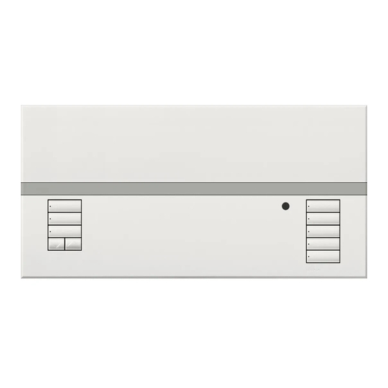
The GRAFIK Eye QS with EcoSystem
control unit allows for control of both lights
and shades, without interfaces, using
a single control unit. Features include
pushbutton scene recall, info screen
that displays energy savings and status,
IR receiver, astronomic timeclock, contact
closure input, and engravable backlit
buttons that are easy to find and operate.
The built-in EcoSystem bus link can control
up to 64 EcoSystem devices.
LUTRON
220 - 240 V~ 50/60 Hz
3000 W
3000 VA / 2400 W
40 – 1200 W
40 – 1200 VA / 40 – 960 W
Class 2 ratings.
®
For California residents only:
The batteries in these devices contain Perchlorate Material –
special handling may apply.
For more information, visit www.dtsc.ca.gov/hazardouswaste/perchlorate
Advertisement
Table of Contents
Troubleshooting

Related Manuals for Lutron Electronics GRAFIK Eye QS with EcoSystem


Summary of Contents for Lutron Electronics GRAFIK Eye QS with EcoSystem
- Page 1 ® with EcoSystem Control Unit Installation and Operation Guide Please Read The GRAFIK Eye QS with EcoSystem control unit allows for control of both lights and shades, without interfaces, using a single control unit. Features include pushbutton scene recall, info screen...
-
Page 2: Table Of Contents
Diagnostics ......28 GRAFIK Eye QS with EcoSystem Control Unit Installation and Operation Guide 2... -
Page 3: Features And Functions Of The
Features and Functions of the GRAFIK Eye QS with EcoSystem Control Unit Hinged faceplate Page button Switches between displaying Info screen zones 1 to 8 and 9 to 16 on Displays status or 16-zone unit programming functions Master buttons Temporarily raise and lower... -
Page 4: And Ecosystem Wiring
Power module * For a complete list of approved dimmable LEDs please call 1.800.523.9466 or or interface visit www.lutron.com/dimcflled GRAFIK Eye QS with EcoSystem Control Unit Installation and Operation Guide 4 ®... -
Page 5: Grafik Eye Qs With Ecosystem
Switch connecting the loads to the (110 mm) GRAFIK Eye QS with EcoSystem control unit, test the loads for Load short-circuits. Neutral LUTRON (continued on next page) GRAFIK Eye QS with EcoSystem Control Unit Installation and Operation Guide 5 ®... - Page 6 Terminals 1, 2, 3: Dimmed/Switched line voltage outputs Notice: Risk of damage to unit. GRAFIK Eye QS with EcoSystem control units must be in stalled by a qual i fied electrician in accordance with all applica ble reg u la tions and building codes.
-
Page 7: Ecosystem Bus Wiring Details
WARNING! Shock hazard. May and C-PCBL-216-CL-1 (plenum). result in serious injury or death. Do not wire live. Interrupt power via circuit breaker before wiring and servicing the EcoSystem bus supply. GRAFIK Eye QS with EcoSystem Control Unit Installation and Operation Guide 7 ®... -
Page 8: Overview Of Iec Pelv/Nec ® Class 2 Wiring
Note: The GRAFIK Eye QS control unit must be powered by a Normal/Emergency distribution panel for proper ELI operation. Refer to the LUT-ELI-3PH Installation Guide for the complete wiring diagram. GRAFIK Eye QS with EcoSystem Control Unit Installation and Operation Guide 8 ®... -
Page 9: Qs Link Control Wiring Details
• For more information regarding Lutron cable specifications, please see Lutron P/N 369596 and P/N 369597 at www.lutron.com • For wire runs over 2000 ft (610 m), please contact Lutron Customer Assistance LUTRON LUTRON GRAFIK Eye QS with EcoSystem Control Unit Installation and Operation Guide 9 ®... -
Page 10: Powering More Than 3 Wallstations Example
(continued) Powering More Than 3 Wallstations Example The GRAFIK Eye QS with EcoSystem control unit can power up to 3 seeTouch wallstations. An external 24 V- power supply is required to power more than 3 wallstations. • The Common wire from the power supply •... -
Page 11: Completing Installation Of The Grafik Eye Qs With Ecosystem Control Unit
3. Apply the protective overlay to the hinged cover and faceplate control unit. will open fully, as shown. Protective overlay (apply after installation) GRAFIK Eye QS with EcoSystem Control Unit Installation and Operation Guide 11 ®... -
Page 12: General Functionality
LED bar indicate the unit’s current page. Upon switching pages, the LED bars for all 8 zones of that page will show their level for the current scene. GRAFIK Eye QS with EcoSystem Control Unit Installation and Operation Guide 12 ®... -
Page 13: Pre-Programmed Button Functionality
Pre-Programmed Button Functionality The GRAFIK Eye QS with EcoSystem control unit controls most lighting loads without special programming. Each unit ships with pre-programmed default settings for the scene and shade buttons. For load types other than those shown below (dimmable or non-dim), assign the load type before proceeding. -
Page 14: Zone Button Operation
UA = Unaffected (lights are not affected by scene button or Master buttons) • Press lower to turn zone off LED on LED off Note: To set zone types, see the zone setup section. GRAFIK Eye QS with EcoSystem Control Unit Installation and Operation Guide 14 ®... -
Page 15: Programming Mode
Pressing it repeatedly will eventually return you to the main menu, but will not exit programming mode. When the screen displays a Yes/No question, the Timeclock button is “No”. GRAFIK Eye QS with EcoSystem Control Unit Installation and Operation Guide 15 ®... -
Page 16: Wireless Mode
• Connect the equipment into an outlet on a circuit different from that to which the receiver is connected. • Consult the dealer or an experienced radio/TV technician for help. GRAFIK Eye QS with EcoSystem Control Unit Installation and Operation Guide 16 ®... -
Page 17: Zone Setup
Saved as Unaffected.) Press the “OK” button to accept. 5. The info screen will confirm that your load type has been saved. 6. Exit programming mode. GRAFIK Eye QS with EcoSystem Control Unit Installation and Operation Guide 17 ®... -
Page 18: Setting Load Types
— RGB/CMY DMX EcoSystem switching (e.g., XPJ) Non-dim digital — * Use incandescent load type unless otherwise specified in the LED product selection tool available at www.lutron.com/ledtool. GRAFIK Eye QS with EcoSystem Control Unit Installation and Operation Guide 18 ®... -
Page 19: Setting High End Or Low End Trim
Note: Non-dim loads will turn off regardless of the minimum level setting. 3. The info screen will confirm that your minimum level has been saved. 4. Exit programming mode. Saved Saved GRAFIK Eye QS with EcoSystem Control Unit Installation and Operation Guide 19 ®... -
Page 20: Labeling A Zone (Optional)
7. The info screen will confirm that your name has been saved. 8. Exit programming mode. Note: On 16-zone units, use the page button to access all zones. Label zone 2 1 / 11 1: A Saved GRAFIK Eye QS with EcoSystem Control Unit Installation and Operation Guide 20 ®... -
Page 21: Scene Setup
7. The info screen will confirm that your scene has been saved. Scene 1 8. Exit programming mode. Set shade Groups Zone raise Zone lower Saved GRAFIK Eye QS with EcoSystem Control Unit Installation and Operation Guide 21 ®... -
Page 22: Labeling A Scene (Optional)
8. Exit programming mode. Scene 1 when that scene is active. Press OK to save. Daylighting 6. Exit programming mode. Enable Saved Saved GRAFIK Eye QS with EcoSystem Control Unit Installation and Operation Guide 22 ®... -
Page 23: Setting Save Mode
• To set a zone to unaffected (---), press and hold the zone lower button for 6 seconds after the zone has gone to 0% light level. GRAFIK Eye QS with EcoSystem Control Unit Installation and Operation Guide 23 ®... -
Page 24: Ecosystem Setup
If a device does not respond, repeat the “Build System” command and/or check the wiring. Searching... Found x Loads Found GRAFIK Eye QS with EcoSystem Control Unit Installation and Operation Guide 24 ®... -
Page 25: Assigning/Unassigning An Ecosystem Device
(each device can be assigned to only 1 zone at a time). • Devices can be assigned only to zones set to EcoSystem load type. • Refer to the Zone Setup section for instructions on changing load type. GRAFIK Eye QS with EcoSystem Control Unit Installation and Operation Guide 25 ®... -
Page 26: Addressing Ecosystem Devices
4. To program new/replacement devices, follow the instructions to assign EcoSystem devices to a zone. Address all 5. Exit programming mode. Address all ? Press OK Searching... Found x Loads Found GRAFIK Eye QS with EcoSystem Control Unit Installation and Operation Guide 26 ®... -
Page 27: Reset Missing Ballast Addresses
*This screen menu is only available in units with software revision 9.003 or higher. If you want to reset ballasts on a unit with an older version of software, please contact Lutron Customer Support. GRAFIK Eye QS with EcoSystem Control Unit Installation and Operation Guide 27 ®... -
Page 28: Diagnostics
Link Silence “EcoSystem” menu. 3. The info screen will confirm that the selected link status is saved. Silence Ballast Link Silence GRAFIK Eye QS with EcoSystem Control Unit Installation and Operation Guide 28 ®... -
Page 29: Contact Closure Input (Cci) Setup
5. The info screen will confirm that your setting has been saved. CCI menu 6. Exit programming mode. CCI Mode CCI Type CCI Mode Saved Occupancy Saved (continued on the next page) GRAFIK Eye QS with EcoSystem Control Unit Installation and Operation Guide 29 ®... - Page 30 CCI Type closure. The CCI must be set to “Maintained” (default) for proper “Emergency Mode” operation. Maintained Saved Saved GRAFIK Eye QS with EcoSystem Control Unit Installation and Operation Guide 30 ®...
-
Page 31: Occupancy Sensor Setup
Wired to Eco device 4. Assign sensor actions. LUTRON LUTRON 5. Configure sensor settings (optional). LUTRON Wireless to QSM GRAFIK Eye QS with EcoSystem Control Unit Installation and Operation Guide 31 ® LUTRON Wireless to QSM Wireless to Gra k Eye... -
Page 32: Associating Wireless Occupancy Sensors
Note: The wireless signal has a range of 30 ft (9 m) through standard construction or 60 ft (18 m) line of sight. QS Sensor Module (QSM) GRAFIK Eye QS with EcoSystem Control Unit Installation and Operation Guide 32 ®... -
Page 33: Selecting The Mode
Occ Sensor Saved Saved Scene Mode Zone Mode * Applicable only to units that ship with firmware version 9.003 and higher. Previous versions support up to 4 sensors. GRAFIK Eye QS with EcoSystem Control Unit Installation and Operation Guide 33 ®... -
Page 34: Scene Mode
Scene 1 Scene Off 3 seconds Setup * Applicable only to units that ship with firmware version 9.003 and higher. Previous versions support up to 4 sensors. GRAFIK Eye QS with EcoSystem Control Unit Installation and Operation Guide 34 ®... -
Page 35: Zone Mode
“OK” button to save. 4. Exit programming mode. Occ Sensor Occupied Unoccupied Actions Saved Saved Select Occupied Select Unoccupied 3 seconds Level Level Setup GRAFIK Eye QS with EcoSystem Control Unit Installation and Operation Guide 35 ®... -
Page 36: Labeling An Occupancy Sensor (Optional)
Repeat for all desired sensors. 7. Exit programming mode. Sensor xxxxxxxx yyyy-yyyy Label sensor x/y 1 / 11 1: A Saved Saved GRAFIK Eye QS with EcoSystem Control Unit Installation and Operation Guide 36 ®... -
Page 37: Configuring Occupancy Sensor Settings
7. The info screen will confirm that your setting has been saved. 8. Exit programming mode. * Applicable only to units that ship with firmware version 8.027 and higher. Previous versions support settings between 15–30 seconds. GRAFIK Eye QS with EcoSystem Control Unit Installation and Operation Guide 37 ®... -
Page 38: Daylight Sensor Setup
3. Assign sensors to zones or groups. LUTRON 4. Calibrate the system to achieve the desired response to natural light. Note: The Daylighting feature is not supported for the DMX load type. GRAFIK Eye QS with EcoSystem Control Unit Installation and Operation Guide 38 ®... -
Page 39: Associating Wireless Daylight Sensors
Note: The wireless signal has a range of 30 ft (9 m) through standard construction or 60 ft (18 m) line of sight. GRAFIK Eye QS with EcoSystem Control Unit Installation and Operation Guide 39 ®... -
Page 40: Assigning The Mode
Daylight Sensor Daylight Sensor screen. Note: Changing modes will remove all previous daylight Mode assignments. Setup Daylight Sensor Daylight Sensor Saved Saved Zone Group GRAFIK Eye QS with EcoSystem Control Unit Installation and Operation Guide 40 ®... -
Page 41: Zone Mode
Sensor Name Adjust Light Daylight Sensor “Cal” Radio Powr Savr button Daylight Sensor More light Setup Saved Saved Zone 1 3 seconds Calibrate Less light GRAFIK Eye QS with EcoSystem Control Unit Installation and Operation Guide 41 ®... -
Page 42: Group Mode
This step allows you to assign daylight sensors to a group of EcoSystem loads Master buttons connected to the GRAFIK Eye QS with EcoSystem control unit. You may also assign 9-16 daylight sensors to line-voltage zones in this mode. Each group can be assigned to “OK”... - Page 43 Note: If wireless sensors are not found, verify that they are associated correctly. Daylight Sensor Calibrate Adjust Light Setup More light Saved Saved Group 1 3 seconds Less light Calibrate GRAFIK Eye QS with EcoSystem Control Unit Installation and Operation Guide 43 ®...
-
Page 44: Labeling A Daylight Sensor (Optional)
Repeat for all desired sensors. 7. Exit programming mode. Sensor xxxx-xxxx Label sensor x/y 1 / 11 1: A Saved Saved GRAFIK Eye QS with EcoSystem Control Unit Installation and Operation Guide 44 ®... -
Page 45: Pico Wireless Control Setup
2 In scene function, the starting scene of the Pico wireless control is selectable and zone levels in each scene can be adjusted by following the instructions in Scene Setup. ® GRAFIK Eye QS with EcoSystem Control Unit Installation and Operation Guide 45 ®... -
Page 46: Wireless Control Unit
Note: The wireless signal has a range of 30 ft (9 m) through standard Bottom/Off construction or 60 ft (18 m) line of sight. button Pico Wireless Control GRAFIK Eye QS with EcoSystem Control Unit Installation and Operation Guide 46 ®... -
Page 47: Associating Through A Qs Sensor Module
On the Pico wireless control, press and hold the top and bottom buttons for 3 seconds until the LEDs on the GRAFIK Eye control unit stop flashing and the QSM beeps 1 time. GRAFIK Eye QS with EcoSystem Control Unit Installation and Operation Guide 47 ®... -
Page 48: Ir Setup
Remote Remote LUTRON QS Sensor Module Wired IR IR Eye LUTRON LUTRON (QSM) GRAFIK Eye QS Receiver GRAFIK Eye QS control unit control unit GRAFIK Eye QS with EcoSystem Control Unit Installation and Operation Guide 48 ® Wired to QSM... -
Page 49: Enabling/Disabling The Ir Receiver
“OK” button to accept. The info screen will confirm that your Programming settings have been saved. 5. Exit programming mode. Integral IR Enabled Saved Saved GRAFIK Eye QS with EcoSystem Control Unit Installation and Operation Guide 49 ®... -
Page 50: Associating The Qs Ir Eye With A Grafik Eye Qs Control Unit
5. Point the IR remote at the QS IR Eye. To exit programming mode, press and hold the top and bottom buttons on the remote for 3 seconds. Button Setup First Scene QS IR Eye Saved Saved GRAFIK Eye QS with EcoSystem Control Unit Installation and Operation Guide 50 ®... - Page 51 1 second, press and hold the “Off” (bottom) button on the remote for 5 seconds. Change type? QS IR Eye Favorite Button Setup Saved Saved Favorite Scene MIR-ITFS C-FLRC GRAFIK Eye QS with EcoSystem Control Unit Installation and Operation Guide 51 ®...
-
Page 52: Associating Through A Qs Sensor Module
IR receivers and repeat as needed. Press OK Exit programming mode on the GRAFIK Eye QS control unit. Wired IR Change type? Change type? Receiver Saved Saved Zone Scene GRAFIK Eye QS with EcoSystem Control Unit Installation and Operation Guide 52 ®... -
Page 53: Associating Sivoia Qs Shades/Drapes And Grafik Eye Qs Control Units
The top and bottom LEDs Note: The wireless signal has a range of 30 ft (9 m) through will stop flashing. standard construction or 60 ft (18 m) line of sight. GRAFIK Eye QS with EcoSystem Control Unit Installation and Operation Guide 53 ®... -
Page 54: Adjusting Shade Settings
The LED next to the bottom button limits can be adjusted. will flash quickly for 2 seconds. GRAFIK Eye QS with EcoSystem Control Unit Installation and Operation Guide 54 ®... -
Page 55: Preset Adjustment: Simple Method
2. Press and release the middle button on that shade button group. The adjacent LED will blink rapidly. EDUs for assigned shades will automatically move to their current preset settings. GRAFIK Eye QS with EcoSystem Control Unit Installation and Operation Guide 55 ®... -
Page 56: Naming A Group Of Shades
1: A Saved * Applicable only to units that ship with firmware version 9.003 and higher. For previous versions, skip step 2 and proceed to step 3. GRAFIK Eye QS with EcoSystem Control Unit Installation and Operation Guide 56 ®... -
Page 57: Enable/Disable "Stop If Moving" Functionality
6. Once the process is complete, hit the back button to go back to the main menu. For each shade ‘Open’ Enables Open button Shade button group Shade Group N... Close button Stop If Moving Disabled GRAFIK Eye QS with EcoSystem Control Unit Installation and Operation Guide 57 ®... -
Page 58: Associating Sivoia Qs Triathlon Shades With Grafik Eye Qs Control Unit
Close button in that group for 6 seconds. All LEDs in the Shade button group and the Shade button LED will flash then turn off. GRAFIK Eye QS with EcoSystem Control Unit Installation and Operation Guide 58 ®... -
Page 59: Setting Upper And Lower Limits Of A Sivoia Qs Triathlon Shade With Grafik Eye Qs Control Unit
6. Set the lower limit: Repeat steps 2 and 3 9. Repeat steps 1 through 8 to set the to enter Limit Set mode. upper and lower limits for each Sivoia QS Triathlon shade. GRAFIK Eye QS with EcoSystem Control Unit Installation and Operation Guide 59 ®... -
Page 60: Associating Multiple Grafik Eye Qs Control Units
Master button unit B replicates presses activated scene activations on control unit A are and Master button replicated on control presses on control unit B. unit A. GRAFIK Eye QS with EcoSystem Control Unit Installation and Operation Guide 60 ®... -
Page 61: Timeclock Operation
8. Exit programming mode. 12 Hr Set time : 00 AM Set time 08 : Set date Set date Set date Saved : 00 2009 March GRAFIK Eye QS with EcoSystem Control Unit Installation and Operation Guide 61 ®... -
Page 62: Setting Location
4. Press the “OK” button to accept. The info screen will confirm that City your time and date have been saved. Saved 5. Exit programming mode. Philadelphia GRAFIK Eye QS with EcoSystem Control Unit Installation and Operation Guide 62 ®... -
Page 63: Adding An Event
9. The info screen will confirm that your event has been saved. 10. Repeat steps 4 through 9 for additional events. 11. Exit programming mode. Set time Add events Saved Scene : 00 AM Scene 1 GRAFIK Eye QS with EcoSystem Control Unit Installation and Operation Guide 63 ®... -
Page 64: Deleting An Event
“OK” button to Monday Monday accept. 4. Press the “OK” button to return to the Timeclock menu. Deleted 5. Exit programming mode. View 8:00 AM Scene 5 GRAFIK Eye QS with EcoSystem Control Unit Installation and Operation Guide 64 ®... -
Page 65: Setting A Holiday
3. Press the “OK” button to delete the Monday selected holiday. The info screen will Feb 14 confirm that your holiday has been deleted. 4. Exit programming mode. Delete holiday Deleted Delete? GRAFIK Eye QS with EcoSystem Control Unit Installation and Operation Guide 65 ®... -
Page 66: Copying A Schedule
4. The info screen will ask you to confirm deleting the schedule on the selected day; press the “OK” button to accept. Saved 5. Exit programming mode. Delete Sunday schedule? Deleted GRAFIK Eye QS with EcoSystem Control Unit Installation and Operation Guide 66 ®... -
Page 67: Afterhours
Afterhours scene: The scene that the GRAFIK Eye QS control unit will activate when the Delay to off expires. Range: Scenes 1 to 16, Off (default Scene off) (See example on the next page.) GRAFIK Eye QS with EcoSystem Control Unit Installation and Operation Guide 67 ®... -
Page 68: Afterhours Examples
Delay to flash Delay to off Afterhours Scene Delay to flash Delay to off Afterhours Scene (lights (lights flash) flash) Button press: Button press: Office worker Security guard GRAFIK Eye QS with EcoSystem Control Unit Installation and Operation Guide 68 ®... -
Page 69: Setting Up Afterhours
“OK” button to accept. The info screen will confirm Delay to off Afterhours that “Afterhours” mode is ended. Saved 4. Exit programming minutes Scene off mode. GRAFIK Eye QS with EcoSystem Control Unit Installation and Operation Guide 69 ®... -
Page 70: Diagnostics And Special Settings
USB status. There is Link info also an option to reset the USB connection (do this only if asked to by Lutron Customer Assistance). 3. Exit programming mode. GRAFIK Eye QS with EcoSystem Control Unit Installation and Operation Guide 70 ®... -
Page 71: Setting The Security Password
To disable your password, follow Steps Password 1 through 4 of “Setting the Security Set Password Password”, and select “Disable” on the Password menu. Disable GRAFIK Eye QS with EcoSystem Control Unit Installation and Operation Guide 71 ®... -
Page 72: Language Selection
“OK” button to select and save. Master buttons 9-16 “OK” button Timeclock Pull down to remove (back) button bottom faceplate GRAFIK Eye QS with EcoSystem Control Unit Installation and Operation Guide 72 ®... -
Page 73: Troubleshooting
Set the latitude and longitude of the unit’s location not occur at the correct time Holiday schedule is in effect Normal schedule will resume when the holiday ends GRAFIK Eye QS with EcoSystem Control Unit Installation and Operation Guide 73 ®... -
Page 74: Troubleshooting: Wireless Functions
Info screen often prompts Unit wireless mode set to “Enabled” and nearby Change wireless mode to “Ignore Programming” for wireless device wireless systems are being programmed association GRAFIK Eye QS with EcoSystem Control Unit Installation and Operation Guide 74 ®... -
Page 75: Troubleshooting: Shade Functions
Limits must be set manually on the Sivoia QS wireless EDU (see Sivoia QS wireless shade Sivoia QS wireless shades installation guide) through the GRAFIK Eye QS control unit. GRAFIK Eye QS with EcoSystem Control Unit Installation and Operation Guide 75 ®... -
Page 76: Troubleshooting: Ecosystem Functions
EcoSystem device at full E1 and E2 are not connected Check E1 and E2 connections on the back of the GRAFIK Eye QS with EcoSystem control unit brightness cannot be EcoSystem link is overloaded Reduce number of EcoSystem devices on link to 64 or fewer. Check voltage: Minimum voltage... -
Page 77: Warranty
Electronics Co., Inc. Other countries: +65.6220.4666 MATERIALS PROVIDED BY LUTRON, IT DOES NOT FORM A © 2015-2018 Lutron Electronics Co., Inc. PART OF THE BASIS OF ANY BARGAIN BETWEEN LUTRON AND CUSTOMER AND WILL NOT IN ANY WAY BE ENFORCEABLE BY CUSTOMER.
Need help?
Do you have a question about the GRAFIK Eye QS with EcoSystem and is the answer not in the manual?
Questions and answers