
Related Manuals for Lutron Electronics LCP128


Summary of Contents for Lutron Electronics LCP128
- Page 1 LCP128 D i m m i n g a n d S w i t c h i n g S S y y s s t t e e m m Setup and Maintenance Guide...
-
Page 3: Table Of Contents
Troubleshooting Guide Troubleshooting Guide........................55 Maintenance Maintenance............................60 Glossary of Terms Glossary of Terms..........................61 Tables Panel Tables ............................62 Module Type Table..........................66 Load Type Table ..........................67 Control Location Table........................68 Control Station Table .........................69 Time Clock Event Table ........................71 LCP128 Setup and Maintenance Guide... -
Page 4: How To Use This Guide
Tables are provided at the back of this guide to record the above information. Photocopy the tables as needed, and leave them for the occupant after they are completed. Note: For mounting and wiring information, refer to the LCP128 Installation Guide, Lutron P/N 032-150. System Overview Diagram Control Link 2000 ft. -
Page 5: System Specifications
Introduction System Specifications LCP128 is a lighting control system designed for commercial buildings. It consists of up to 8 dimming panels and up to 32 control stations. Control stations can be wallstations, key switches, contact closure input and output devices (OMX-AV), contact closure output devices (OMX-CCO-8), or building management system interfaces (OMX-RS232). - Page 6 (OMX-RS232). Emergency Power Mode When a LCP128 panel is placed into emergency power mode (loss of normal power), circuits are changed to emergency settings and remain at those settings until the controller exits emergency power mode (return of normal power). All control station inputs and time clock events are ignored while in emergency power mode.
-
Page 7: System Start-Up Checklist
LCP128 System Start-Up Checklist for Electrical Contractor Important Note: To ensure that the LCP128 System is ready for Start-Up, please complete the following checklist. The LCP128 panel(s) and control station(s) have been mounted in accordance with the installation instructions. Control stations have been wired to the panel in accordance with installation instructions. -
Page 9: Controller Overview
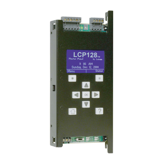
Controller Overview LCP128 Controller Layout Digital Link Transmit (TX) LED Digital Link Receive (RX) LED Panel Contact Closure Inputs Connector Digital Control Station Link and Emergency Sense Line Connector LCD Screen LCP128 Right Soft Labeled Left Soft Labeled Button Button... - Page 10 Controller Overview Navigation The LCP128 controller uses certain methods for navigating, selecting, setting values, etc. Please read this section carefully before using the controller to program your system. The LCP128 controller has nine buttons below the display. The table below explains their functions.
- Page 11 Intermediate screens have the soft labeled buttons “Previous” and “Next”, and the last screen has the Afterhours Setup soft Labeled buttons “Previous” and “Done”. Note: Data is not stored in the LCP128 system database until “Done” is selected. Flash Count: Previous...
- Page 12 Espanol Portugues then press (Done). Italiano Done Getting Started - The Home LCP128 Screen by Lutron • When the controller is first powered or is not used for 20 minutes, the display shows the Home 8:00 AM screen. Pressing (the Home button) always Wednesday, Nov 3, 2004 takes you back to this screen.
- Page 13 Station”. This could also indicate a control station address conflict. • If the unit is present and is not a control that is known to the system, the control is labeled as “???”. This could also indicate a control station address conflict. LCP128 Setup and Maintenance Guide...
-
Page 14: Step-By-Step Programming Instructions
Step by Step Programming Instructions Overview Programming your LCP128 system is done in seven steps. 1. Panel Configuration This step selects a language for the controller LCD and configures the load setup. For multiple panel systems, this step also assigns panel addresses and configures the number of circuits in each panel. -
Page 15: Step 1: Panel Configuration
For example, if Panel 1 has 12 circuits, the first circuit in Panel 2 will be circuit 13 on the LCP128 controller. The figure below shows a sample system. Note: If your system has only one panel, you do not need to set the panel configuration. The panel address, first system circuit number, and number of circuits are preprogrammed. - Page 16 Load Setup and press (OK). System Size C. Use to highlight System Size and press (OK). How many circuits D. Use to set the total number of system are in this system? circuits and press (Done). Cancel Done LCP128 Setup and Maintenance Guide...
- Page 17 Panel 3 address = 03 Master Programming Panel Etc. Cancel Next Circuit Offset Setup What is the first system circuit number in this panel? Previous Next Circuit Offset Setup How many circuits are in this panel? Previous Done LCP128 Setup and Maintenance Guide...
- Page 18 STEP 1 (continued) Module Type Setup Panel Setup Panel Addressing Your LCP128 system contains modules configured with one or more outputs (circuits). The module Load Setup types are set by the model numbers of the panels Emergency Setup in the system. Complete the Module Type Table at...
- Page 19 Load Type setup is now complete and all dimmed with phase control dimming before settings are saved in the event of a power setting to any load type other than Non-Dim. failure. LCP128 Setup and Maintenance Guide...
- Page 20 NA (not any). E. When all the trim levels are set press (Done). Caution! Do not reduce the low end trim on a fluorescent load type. This will decrease lamp life and may damage ballasts. LCP128 Setup and Maintenance Guide...
- Page 21 Chicago Setup and - 10% press (OK). Relay - O N D. Use to select a circuit and set the Chicago limit. When all the circuit limits are Cancel Done set press (Done). LCP128 Setup and Maintenance Guide...
-
Page 22: Step 2: Time Clock Configuration
Time Clock Configuration The LCP128 system can be programmed to initiate scenes and other actions automatically at either a specific time of day or at a time relative to sunrise or sunset. It is important to configure the time clock as needed for your location. - Page 23 The first 2 digits are the month, the middle 2 are the day, and the last 4 are the year. Cancel Done C. Press (Done) to save changes. LCP128 Setup and Maintenance Guide...
- Page 24 39.6N degrees. The minutes are Set Time Zone converted to a decimal of a degree by dividing by GMT -5:00 Eastern Time GMT -4:00 Atlantic Time GMT -3:30 Newfoundland GMT -3:00 Brasilia Previous Next LCP128 Setup and Maintenance Guide...
- Page 25 If no offset is required, leave the offsets at 0:00 (default). Press (Done) to save changes. Note: Do not use this function to compensate for daylight savings time. For procedures on how to program daylight savings time settings, refer to the next page. LCP128 Setup and Maintenance Guide...
- Page 26 Current Setting • The start month, week, and day. United States • The end month, week, and day. • The number of minutes to adjust for daylight savings time, up to 120 minutes. Previous Done LCP128 Setup and Maintenance Guide...
-
Page 27: Step 3: Scene Modification
The LCP128 system comes with 32 pre-configured scenes and 1 Off scene (see the table below for default scene settings). As you program your system, you can assign these scenes to time clock events. For example, at 6 PM each evening certain dimming circuit levels rise and additional circuits turn on. - Page 28 E. For dimming circuits affected by the scene, use to set a fade time and press (Next). F. For a combination of dimming and switching circuits, use to set whether switches react at Start of Fade or End of Fade. Then press (Done). LCP128 Setup and Maintenance Guide...
-
Page 29: Step 4: Control Stations
STEP 4 Control Stations Control stations are connected to the LCP128 panel via the digital control link. Control stations can be wallstations (with various numbers of buttons), key switches (NTOMX-KS), contact closure input and output devices (OMX-AV), contact closure output devices (OMX-CCO-8), or OMX-RS232 interfaces. Each control station must be assigned a unique address. - Page 30 Next and press (Next). Refer to the following pages to program each type of action. Address 01 Setup Button 01 Button 02 Button 03 Previous Next Address 03 Button 01 Action: Lower Circuits Previous Next LCP128 Setup and Maintenance Guide...
- Page 31 Fade Time and press Start of Fade K. For a combination of dimming and switching Previous Done circuits, use to set when the switches react (Start of Fade or End of Fade). Then press LCP128 Setup and Maintenance Guide...
- Page 32 I. For dimming circuits affected by the action, use to set the Fade Time. J. For a combination of dimming and switching circuits, use to set when the switches react (Start of Fade or End of Fade). Then press LCP128 Setup and Maintenance Guide...
- Page 33 Refer to “Configure Address 03 Setup the Wallstations” earlier in STEP 4. Clockwise Turn Counter - Clockwise Turn Previous Next Address 03 Key Switch Action: Scene Previous Next LCP128 Setup and Maintenance Guide...
- Page 34 Panel CCI Setup Note: For contact closure inputs wired directly to Back the LCP128 panel, refer to STEP 6. A. From the Main Menu use to highlight Control Station Setup Control Station Setup and press (OK).
- Page 35 The OMX-RS232 is packaged and shipped with a protocol document that details how to execute each command. Only a subset of the commands Address 03 Setup in that document work with the LCP128 system and they are listed below: Command LCP128 Function...
-
Page 36: Step 5: Time Clock Events
Before proceeding with STEP 5, complete the Time Clock Event Table located at the back of this guide. Record when each event should occur and what it should do. Afterhours Delay Warn Time Delay Warn Time Delay LCP128 Setup and Maintenance Guide... - Page 37 Note: For Afterhours End, this step is complete. Cancel Next Event Time Type Time Fixed Time Fixed 08:00 AM Previous Next Event Time Type Time Sunrise Sunrise + 00:15 HH : MM Previous Next LCP128 Setup and Maintenance Guide...
- Page 38 To add another event to this same schedule, select Yes when prompted “Modify More Events?” Note: You will set the afterhours warn time, flash count, and off delay later in STEP 5. LCP128 Setup and Maintenance Guide...
- Page 39 Program the action using the same method as for a weekly event. Refer to “Adding Weekly Events” Number of Days: earlier in STEP 5. Note: For Afterhours End, this step is complete. Previous Next LCP128 Setup and Maintenance Guide...
- Page 40 F. You are asked to confirm deleting the event(s). Sun - Sunrise +0:15 Press Yes to delete, otherwise press No. To delete another event from that day or holiday, Sun - Sunset -0:30 select Yes when prompted to “Delete Another?”. Previous Done LCP128 Setup and Maintenance Guide...
- Page 41 Emergency Setup Notes: To add an afterhours start action, refer to “Adding Afterhours Setup Weekly Events” earlier in STEP 5. Choose Language 120 minutes is the maximum allowable off delay Back in California Title 24. LCP128 Setup and Maintenance Guide...
-
Page 42: Step 6: Panel Contact Closure Inputs
STEP 6 Panel Contact Closure Inputs The LCP128 controller has two contact closure inputs (see illustration below). Separate actions can be defined for the opening and closing of the contact. The choices are: • Scene or Custom Scene - Each time the contact closure input is activated, the assigned circuits go to the programmed scene. - Page 43 F. For dimming circuits affected by the action, use to set the Fade Time. G. For a combination of dimming and switching circuits, use to set when the switches react (Start of Fade or End of Fade). Then press LCP128 Setup and Maintenance Guide...
- Page 44 Fade Time and press switches react? Start of Fade H. For a combination of dimming and switching circuits, use to set when the switches react (Start of Fade or End of Fade). Then press Previous Done LCP128 Setup and Maintenance Guide...
- Page 45 G. For dimming circuits affected by the action, use to set the Fade Time and press H. For a combination of dimming and switching circuits, use to set when the switches react (Start of Fade or End of Fade). Then press LCP128 Setup and Maintenance Guide...
-
Page 46: Step 7: Emergency Power Mode
• The essential and non-essential panels must be connected by a sense line wired to terminal 5 on the link connector on the LCP128 controller, see illustration below. (For wiring details see the LCP128 Installation Guide). In this configuration, the emergency (essential) lighting panel will “sense” the normal panels’ power. When normal power is lost, the emergency panel will go to the emergency settings (factory set to all circuits On). - Page 47 --- (unaffected). When the outputs are programmed press (Done) to update the database. F. For multi-panel systems, repeat the procedure to program the emergency settings at each remote panel. LCP128 Setup and Maintenance Guide...
- Page 48 Your LCP128 System is now programmed and ready to use. Important: Keep this guide with the system. It should include the completed Control Location, Panel, Module Type, Load Type, and Control Station Tables. The rest of this guide is REFERENCE MATERIAL.
-
Page 49: Overrides
The LCP128 controller enables you to perform the following types of overrides: • Circuit Level Override - Directly set a level for a dimming circuit or turn any circuit on or off. The override occurs immediately and remains in effect as long as the Set Circuit Levels screen is displayed on the controller LCD. - Page 50 To exit the Set Circuit Levels screen and return the circuits to what they were before setting overrides, press (Cancel). LCP128 Setup and Maintenance Guide...
- Page 51 Scene: To exit the Select Scene screen and return the circuits to what they were before setting overrides, press (Cancel). Cancel Done LCP128 Setup and Maintenance Guide...
- Page 52 B. Use to highlight Afterhours Override and afterhours mode? press (OK). C. The screen title indicates whether afterhours mode is enabled or disabled. To end afterhours mode press for Yes. (Or press for No.) LCP128 Setup and Maintenance Guide...
-
Page 53: Locking And Unlocking The Controller
Locking and Unlocking the Controller Overview The LCP128 controller may be password protected to prevent unauthorized access to system settings. If no controller buttons are pressed during a user-set time (1-90 minutes), the controller locks automatically. A 4-digit password must be set when locking is configured. This password must be entered before any of the menus can be accessed when the controller is locked. - Page 54 Locking and Unlocking the Controller (continued) Unlocking the Controller LCP128 If the controller is locked, a LOCKED message is displayed on the Home screen. You need to unlock LOCKED by Lutron the controller before you can access the Main 8:00 AM Menu.
-
Page 55: Troubleshooting Guide
(e) Circuit breaker is OFF. (e) Turn the breaker on to verify proper power supply to each circuit. The breaker could be in the LCP128 panel or in a separate distribution panel if the LCP128 is a feed- through panel. -
Page 56: Troubleshooting Guide
“Overrides” section in this guide for more information. do not turn on. (e) Control station link is (e) See the LCP128 Installation Guide for proper wiring. If a mis-wired. T-tap was created to wire a control to the control station link, it should be no longer than 8 ft. -
Page 57: Maintenance
OMX-AV. (d) Control station link is (d) See the LCP128 Installation Guide for proper wiring. If a mis-wired. T-tap was created to wire a control to the control station link, it should be no longer than 8 ft. (2.44m). -
Page 58: Maintenance
(d) Link is mis-wired. (d) See the LCP128 Installation Guide for proper wiring. If a T-tap was created to wire a control to the control station link, it should be no longer than 8 ft. (2.44m). -
Page 59: Maintenance
(c) See ‘Control station buttons do not work’ Symptom of this troubleshooting section. Password is unknown. (a) Contact Lutron Technical Support to unlock the controller. Lutron contact information may be found at the end of this guide. LCP128 Setup and Maintenance Guide... -
Page 60: Maintenance
Caution! Do not spray cleaning solution onto control as it may reach internal components. LCP128 Panels 1. Clean any dirt from air vent openings with a vacuum and check for any obstructions which may block air flow. Keep 12" (30.5 cm) above and below panels unobstructed. -
Page 61: Glossary Of Terms
• LCD (Liquid Crystal Display) - the graphical display • Afterhours Mode - a time clock mode typically built into the LCP128 controller that is used to used for turning selected lights off at the end of a configure the system. -
Page 62: Panel Tables
For each panel, fill in a description for each circuit. Label all spares. • Cross out the circuits that do not exist. • Fill in the system circuit numbers. (continued on next page) Panel 1 Panel 2 Panel System Panel System Description Description Circuit Circuit Circuit Circuit LCP128 Setup and Maintenance Guide... - Page 63 Circuit 1 in panel 1 is system circuit 1. The circuit number is continuous from panel to panel. Continue numbering panels 2 through 4 (if present). Panel 3 Panel 4 Panel System Panel System Description Description Circuit Circuit Circuit Circuit LCP128 Setup and Maintenance Guide...
- Page 64 Panel Tables Panel 5 Panel 6 Panel System Panel System Description Description Circuit Circuit Circuit Circuit LCP128 Setup and Maintenance Guide...
- Page 65 Panel Tables Panel 7 Panel 8 Panel System Panel System Description Description Circuit Circuit Circuit Circuit LCP128 Setup and Maintenance Guide...
-
Page 66: Module Type Table
Record the proper module types for each panel. The LCP128 Panel Model Number The model number for each LCP128 panel in the system indicates the quantity and type of modules present in that panel. L C P - _ X _ S _ D _ Q _ E _ M _ F _ T- 1 2 0 4 M L - 2 0... -
Page 67: Load Type Table
Each circuit in every LCP128 panel must be assigned a load type (see STEP 1 earlier in this guide). The load types available for each circuit depend upon the module type that provides that circuit. Below are the available load types. -
Page 68: Control Location Table
How to Use This Table: Control Location • For each control station, fill in the number of buttons and a brief description or location. Table Address Number of Buttons Location / Description LCP128 Setup and Maintenance Guide... -
Page 69: Control Station Table
Scene - Raise - Lower - Toggle - Delay to Off (DTO), minutes ∗ ∗ ∗ ∗ Kitchen Toggle “ Scene 1 Janitor’s Closet ∗ ∗ DTO, 5 Control Type Sample Control Station / Button LCP128 Setup and Maintenance Guide... - Page 70 How to Use This Table (continued): Control Station • For each button or contact, record the action and which circuits are being controlled. Table (continued) System Circuit / Description LCP128 Setup and Maintenance Guide...
-
Page 71: Time Clock Event Table
Time Clock Event • Fill in a line with the day and time of each time clock event. • For each event, record the action and which circuits are affected. Table Time Action Action Time LCP128 Setup and Maintenance Guide... - Page 72 5,633,540; and corresponding foreign patents. Tel: +49-309-710-4590 Lutron, the sunburst logo, Tu-Wire, and Hi-lume are registered Fax: +49-309-710-4591 trademarks; LCP128 is a trademark of Lutron Electronics Co., Inc. © 2005 Lutron Electronics Co., Inc. Email: lutrongermany@lutron.com Hong Kong Tel: +852-2104-7733...
Need help?
Do you have a question about the LCP128 and is the answer not in the manual?
Questions and answers