Printronix p300 Maintenance Manual
Line printer
Hide thumbs
Also See for p300:
- User's reference manual (153 pages) ,
- User's reference manual (148 pages)
Table of Contents
Advertisement
Advertisement
Table of Contents

Related Manuals for Printronix p300


Summary of Contents for Printronix p300
-
Page 1: Maintenance Manual
P300 / P600 Line Printers Maintenance Manual... - Page 3 P300 / P600 Line Printer Maintenance Manual P/N 140294–001, Rev C...
- Page 4 Printronix, Inc. makes no representations or warranties of any kind regarding this material, including, but not limited to, implied warranties of merchantability and fitness for a particular purpose. Printronix, Inc. shall not...
-
Page 5: About This Manual
Chapter 5: Corrective Maintenance — Contains procedures for printer adjustments, alignments, and replacement of hardware. Appendices — Appendix A lists PROM kit applications for P300 and P600 printers. Appendix B is a PCBA jumper location guide. Appendix C lists part numbers for components replaceable at the field maintenance level, cross–referenced to the illustrations in Chapter 5. - Page 6 P300/P600...
-
Page 7: Table Of Contents
..........4–71 P300/P600... - Page 8 ..........5–65 P300/P600...
- Page 9 ............C–1 P300/P600...
- Page 10 ........2–54 2–36 Paper Feed Control Circuits Block Diagram ......2–55 P300/P600...
- Page 11 ....3–13 3–6 Lubrication, Antirotation Arm, P300 Only ......3–15 4–1...
- Page 12 Paper Ironer Removal/Installation ........5–75 P300/P600...
- Page 13 Tools, Test Equipment, and Supplies ........5–2 P300/P600...
- Page 14 P300/P600...
-
Page 15: Chapter 1. Maintenance Overview
(XQ) configurations, at the field maintenance level. Print speed is the principal difference between P300 and P600 printers. Pedestal and XQ models of a given type differ mainly in type of equipment housing and control panel layout; functionally, they are nearly identical. -
Page 16: Specifications
External Controls and Indicators are illustrated in Figure 1–2 and described in Table 1–1. Internal Controls and Indicators are illustrated in Figure 1–3 and described in Table 1–2. Controls and Indicators for printer options are illustrated in Figure 1–4 and described in Table 1–3. 1–2 P300/P600 Maintenance Overview... -
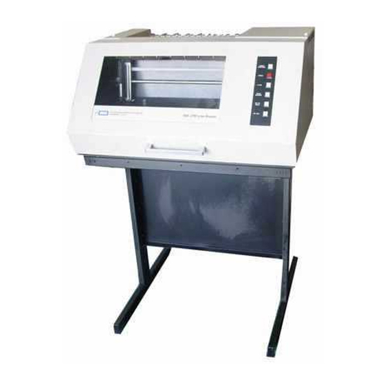
Page 17: Printer: Pedestal Model And Xq Cabinet Model
Figure 1–1. Printer: Pedestal Model and XQ Cabinet Model P300/P600 Maintenance Overview 1–3... -
Page 18: External Controls And Indicators
Press PRINT TEST then ON LINE to activate all Es print test. Printer must be on line to perform print tests. EVFU LOADED Illuminates when an EVFU form definition program Indicator is loaded into printer memory. 1–4 P300/P600 Maintenance Overview... -
Page 19: External Controls And Indicators
Figure 1–2. External Controls and Indicators P300/P600 Maintenance Overview 1–5... -
Page 20: Internal Controls And Indicators
Allows fine positioning of left print margin. Moves Adjustment paper slightly to left or right. Knob Vertical Position Rotate to move paper vertically. Knob Vertical Position Provides reference for setting top of form or first Disk line to be printed. 1–6 P300/P600 Maintenance Overview... -
Page 21: Internal Controls And Indicators
Figure 1–3. Internal Controls and Indicators P300/P600 Maintenance Overview 1–7... -
Page 22: Controls And Indicators For Options On Pedestal Models
DFT/NORM/CPRS Multi–mode print switch. Allows selection of draft, normal, or compressed print as default setting. NOTE: These options are available in kits from Printronix. Figure 1–4. Controls and Indicators for Options on Pedestal Models 1–8 P300/P600 Maintenance Overview... -
Page 23: Chapter 2. Principles Of Operation
2–3. Principal States of Operation NOTE: The bit numbering discussed in the following paragraphs uses a Printronix convention. Bit 1 corresponds to bit 0 in normal convention. Other bits can be converted by subtracting 1 from the Printronix bit number. -
Page 24: Printer System Block Diagram
CONTROL DETECTOR PANEL LOGIC VERTICAL PAPER FEED CONTROL PRINT MECHANISM HAMMER BANK AND DRIVER POWER SUPPLY PAPER FEED RIBBON CONTROL ASSEMBLY PAPER OUT AND PAPER MOTION DETECTOR CIRCUIT BREAKER Figure 2–1. Printer System Block Diagram 2–2 P300/P600 Principles of Operation... -
Page 25: Location Of Functional Elements On Pcbas
Ribbon Control PCBA PCBA (P600 and P600XQ only) Transistor Drivers Ribbon Motors Control Com Line Counter Circuits Reset Timing Logic Tri–state Output Interlock Shuttle Motor Control Logic Circuits Tri–state Shift Reg/Latch Shuttle Fan Control Circuits P300/P600 Principles of Operation 2–3... - Page 26 The printer uses standard interface signals as listed in Table 2–2 c. Print Buffer (Figure 2–2) The print buffer holds a full character line (132, 176, or 220 characters for P300; 132 or 198 for P600). The underline buffer holds a line of single bits.
- Page 27 RAM and the associated character is recirculated. A space character will recirculate the buffer one posi- tion (no underline). A line feed resets the NREC flip–flop and the printer waits to enter the print state. P300/P600 Principles of Operation 2–5...
-
Page 28: Buffer Load State Block Diagram
(198–P600, 15CPI ONLY) (176 OR 220–P300 13.3, 17.1CPI) – – – – – – – – – – – – UNDERLINES IDB1–IDB7 SDUL 1 X 132 (176, 220 – P300 198 – P600) CONTROL NREC NDUL RAM MEMORY CHARACTER NULR... -
Page 29: Interface Block Diagram
DSTB IDSTB INVERT DSTB DR (DATA REQUEST) LOGIC ONL (ON LINE) IONL (DP) RDY (READY) IRDY DRIVERS READY ICPE <BUSY> EDT (ENABLE DATA TRANSFER) ICBY <ACK> 4 usec IACK DELAY Figure 2–3. Interface Block Diagram P300/P600 Principles of Operation 2–7... -
Page 30: Interface Timing
CENTRONICS DATAPRODUCTS msec IDSTB ICSTB LATCH LATCH STB 1 STB 1 STB 2 STB 2 0.5 msec msec DSTB DSTB STB 3 Figure 2–4. Interface Timing 2–8 P300/P600 Principles of Operation... -
Page 31: Interface Signals
IACK Acknowledge signal sent to a Centronics compatible host com– puter, through a driver circuit, to request the next character. Set when ICBY is negated or when ON LINE switch is pressed. P300/P600 Principles of Operation 2–9... -
Page 32: Print State
Character Generation (Figure 2–6 through Figure 2–8) The complete character line (132, 176, or 220 eight bit bytes for P300; 132 or 198 for P600) stored in the buffer is addressed sequentially by the static RAM counter as it is clocked by SRCLK. Each byte ad- dressed is read out as data bits SDB1 through SDB8 and applied to the PROM address control logic deter- mining PROM selection and to the character PROMs themselves. -
Page 33: Dot Selection Block Diagram
COUNT PROM (SERIAL) HAMMER LATCHES BANK P300–44 SHIFT P600–66 REGISTER CHARACTER CC1–CC3 COLUMN SHIFT CLOCK PARALLEL COUNT LOGIC NHSC OUTPUT PROM (SELECT TO DRIVERS/ CHARACTER COILS 1 OF 3) Figure 2–5. Dot Selection Block Diagram P300/P600 Principles of Operation 2–11... - Page 34 “1” bit (dot) or a “0” bit (no dot) for each specific dot column and row. On the P300, only every third bit (representing every hammer location) in the COM data stream is clocked into the hammer driver shift register so that the 44 (132/3) hammer driver circuits may be pulsed.
-
Page 35: Defining The Dot Matrix
DESCENDER DOT LINE 0.02 ” FIRST ROW AND COLUMN OF NEXT CHARACTER LINE (AT 6 LPI) Figure 2–6. Defining the Dot Matrix UPPERCASE LOWERCASE UNDERLINE (REFERENCE) WITH DESCENDER Figure 2–7. Typical Characters (Data Processing Mode) P300/P600 Principles of Operation 2–13... - Page 36 During any SYNC period of a print cycle, the hammer driver shift register contains dot information for a specific dot column within the 12 dot column cell. On the P300, there are 36 SYNC periods for each ham- mer in the dot row, consisting of 12 for each of the three character columns covered by the printing action of each hammer.
- Page 37 1 of the odd character and ending at dot column 12 of the even character. For the P300 shuttle stroke from right to left, operation is the same as for left to right except that dots are loaded and printed beginning at dot column 12 of the third charter and ending at dot column 1 of the first character.
-
Page 38: Dot Column And Character Column Timing For One Shuttle Cycle
–A– P300 –B– P600 Figure 2–9. Dot Column and Character Column Timing for One Shuttle Cycle 2–16 P300/P600 Principles of Operation... -
Page 39: Dot Column And Character Column Counter Block Diagram
MULTIPLEXER COUNTER PROM LOGIC SYNC CHARACTER CC1–CC3 SYNC COLUMN COMPARATOR RESYNC COUNTER COUNT PROM NSPT CONTROL NSPFP SYNC DECODE GATES NEMOV PROM TURNAROUND SYNC LOGIC Figure 2–10. Dot Column and Character Column Counter Block Diagram P300/P600 Principles of Operation 2–17... - Page 40 24 for P600) during which printing occurs. Hammer shift clock, HSC, counter logic is a count of two (three for P300) counters clocked by SRCLK. Its output appears at a comparator which asserts its “equals” output only under the following two conditions: –A modulo three (or two) numbered character is read from the printer buffer and the bits CC1–CC2 are...
-
Page 41: Plotting The Six Bit Code
In plot mode operation, each line of data specifies dots to be printed in a single dot row. The PM signal (instead of the decoded row count) enables the SPFP pulse to generate end of print (EOP) which implies a new buffer load cycle is required. Figure 2–11. Plotting the Six Bit Code P300/P600 Principles of Operation 2–19... - Page 42 Hammer Driver Circuits (Figure 2–12 and Figure 2–13) Each of the print hammers (44 for P300/XQ; 66 for P6000/XQ) is controlled by an electromagnetic coil, a driver, and a logic circuit which, among other functions, controls the energizing of the coil.
- Page 43 –continued The hammer logic circuits perform the following functions: –Convert serial data bits (44 for P300; 66 for P600) on the COM line into parallel data bits (44 for P300; 66 for P600). –Control the energizing of hammer coils to print dots in accordance with the parallel data.
-
Page 44: Hammer Driver Block Diagram
HAMMER DRIVER (H/D) +9.5V REGULATOR HAMMER OUTPUT +36V DISABLE +36V CIRCUITS DARLINGTON DRIVERS (66) FAIL SAFE NHCK DATA LATCHES (66) OPTO– ISOLATORS SHIFT REGISTER (66) NHSC NHSC –B– P600 Figure 2–12. Hammer Driver Block Diagram 2–22 P300/P600 Principles of Operation... -
Page 45: Hammer Driver Circuit Timing
–A– P300 –B– P600 Figure 2–13. Hammer Driver Circuit Timing P300/P600 Principles of Operation 2–23... -
Page 46: Safety Circuits
OR LOSS OF HRS PULSES AFTER TIMEOUT 1 MILLISECOND ONE – SHOT 5 HL MISSING GROUND DIRECT SET +5 HAMMER LEVEL (5 HL) APPLIED OUTPUT ENABLE LATCH – Figure 2–14. Safety Circuits (P600 HD Only) 2–24 P300/P600 Principles of Operation... -
Page 47: Hammer Reset Timer
– Q – ENABLE (176 usec) T1=NSYNCH (2.5 usec) T2=N160H 2.5 CK1 T3=N160H + (2.5n) NSYNCH n = NUMBER OF LOGIC 1 BITS NHSCH NCLK COMH DATA LATCH NSYNCH Figure 2–15. Hammer Reset Timer, P600 P300/P600 Principles of Operation 2–25... - Page 48 0.0139 inches, and no printing occurs. During each of the four printing periods, an entire dot row, three characters wide for P300 and two characters wide for P600, is printed in 36 SYNC periods for P300 and in 24 SYNC periods for P600.
-
Page 49: Dot Row Timing Vs Timing Disk And Cam Position
24 PERIODS PERIODS 24 PERIODS PERIODS 8.57 MSEC 3.9 MSEC 1/2 CAM REVOLUTION (50 MILLISECONDS) 1/2 CAM REVOLUTION (50 MILLISECONDS) RESYNC RESYNC RESYNC –B– P600 Figure 2–16. Dot Row Timing vs Timing Disk and Cam Position P300/P600 Principles of Operation 2–27... -
Page 50: Operation Of Mpu Circuit
Figure 2–17. Operation of MPU Circuit 2–28 P300/P600 Principles of Operation... -
Page 51: Hammer And Shuttle Arrangement
The polarity of the resulting electromagnetic field opposes the field of the permanent magnet, releasing the hammer. The hammer tip strikes the ribbon and paper, leaving a dot of ink. –A– –B– P300 P600 Figure 2–18. Hammer and Shuttle Arrangement P300/P600 Principles of Operation 2–29... -
Page 52: Print Hammer Action
–continued During flight time, the coil is de–energized. As the hammer rebounds after striking, it is recaptured by the permanent magnet. The P300 can produce up to 1000 impacts per second, the P600 up to 1400 impacts per second. A dot row is created by horizontal scanning. All dots in any row of the dot matrix are printed in a single scan as the shuttle moves from one side to the other. -
Page 53: Standard Character Formation
As one of the two low points of the revolving cam turns toward the shuttle, the spring expands, returning the shuttle to the right. –A– P300 –B– P600 Figure 2–20. Standard Character Formation P300/P600 Principles of Operation 2–31... - Page 54 The P300 print mechanism has 44 evenly spaced print hammers fixed to its hammer bank. The hammer bank travels horizontally 3/8 inch while printing. In data processing print mode (300 LPI), each hammer prints the entire dot pattern of three adjacent character columns.
-
Page 55: P600 Phase Fire Operation
12 1 2 3 4 5 6 7 8 9 10 12 1 2 3 4 5 6 7 8 9 10 12 1 2 3 4 5 6 7 8 9 10 Even Hammer Fire Figure 2–21. P600 Phase Fire Operation P300/P600 Principles of Operation 2–33... -
Page 56: Hammer Bank Shuttle Components
P600 SHOWN Figure 2–22. Hammer Bank Shuttle Components 2–34 P300/P600 Principles of Operation... -
Page 57: Paper Feed State
Skip Over Perforation Paper Feed to Top of Form Electronic Vertical Format Unit Programming EVFU Memory Channel Seek Operation Vertical Tab Operation Binary Count Operation Runaway Paper Fault Protection Paper Transport Paper Out Switch Logic P300/P600 Principles of Operation 2–35... - Page 58 The velocity counter counts the 16 microsecond S5 pulses and applies a binary coded address to the velocity PROM. The addressed velocity PROM contents determine the rate at which paper feed pulses are generated during the current period. 2–36 P300/P600 Principles of Operation...
-
Page 59: Paper Feed Logic Block Diagram
PAPER VELOCITY ODD/EVEN FEED COUNTER PULSE NPPF F–F LOGIC LOGIC NOPP STEP COUNTER COUNTER LOGIC NPPF NEMOV LOGIC COUNT ENABLE BOARD NSPFP PAPER FEED PHASE MOTOR GENERATOR LOGIC Figure 2–23. Paper Feed Logic Block Diagram P300/P600 Principles of Operation 2–37... - Page 60 LPI (none at eight LPI). If the character line has no printable characters, the paper moves according to the LPI listed above. 2–38 P300/P600 Principles of Operation...
-
Page 61: Line Feed Operation Velocity Profile
Figure 2–24. Line Feed Operation Velocity Profile P300/P600 Principles of Operation 2–39... -
Page 62: Timing Sequence For Printing One Character Line
–A– P300 Figure 2–25. Timing Sequence for Printing One Character Line 2–40 P300/P600 Principles of Operation... - Page 63 15.5 inches per second during the next 12 row counts on the P600 (8.5 inches per second for the P300). That velocity is maintained until the beginning of the last line of the form FLL is detected. FLL causes the velocity PROM and velocity counter logic to generate paper feed pulses at a lower rate until paper movement stops following the last line of the form.
-
Page 64: Top-Of-Form Counter Block Diagram
1 2 3 4 DECODER (12) 256 X 4 PROM 8 16 32 64 (SKIP–OVER PERFORATION) FMFD F–F NFMD TO PAPER VELOCITY NVRDY F–F TO ROW NEFF COUNTER LOGIC NFMRS Figure 2–26. Top–of–Form Counter Block Diagram 2–42 P300/P600 Principles of Operation... -
Page 65: Top-Of-Form Slewing Velocity Profile
–A– P300 –B– P600 Figure 2–27. Top–of–Form Slewing Velocity Profile P300/P600 Principles of Operation 2–43... -
Page 66: Paper Feed To Top-Of-Form Timing
–A– P300 –B– P600 Figure 2–28. Paper Feed to Top–of–Form Timing 2–44 P300/P600 Principles of Operation... - Page 67 –After the last channel command has been loaded, an end load command is decoded and sent to the load flip–flop. The flip–flop is clocked by NSPI and resets. The EVFU memory is disabled from further loading. The forms length counter stops incrementing immediately, but the EVFU memory accepts the ELD code. P300/P600 Principles of Operation 2–45...
-
Page 68: Evfu Loading Block Diagram
MEMORY COUNTER (4 X 132) NSPI (ENABLE) (CLOCK) INTERFACE NSTL VFU LOAD CONTROL NELD LOGIC NVSC MEMORY ELD (END LOAD) COUNTER LOGIC Figure 2–29. EVFU Loading Block Diagram Figure 2–30. EVFU Loading Sequence Timing Diagram 2–46 P300/P600 Principles of Operation... - Page 69 –The PI line from the host system is active and jumper W5 is absent. –Data bit DB5 is high to generate binary count, BC. –Data bits DB1 through DB4 encode the number of lines to be slewed. P300/P600 Principles of Operation 2–47...
-
Page 70: Evfu Channel Seek Block Diagram
(128) LOGIC (CLOCK) > > COMPARATOR F–F < (RESET) FORM (START LOAD) LENGTH DECODER COUNTER (END LOAD) (CLOCK) RC1–RC4 ROW ONE NDLC (LINE CLOCK) DECODER COUNTER RCLK LOGIC Figure 2–31. EVFU Channel Seek Block Diagram 2–48 P300/P600 Principles of Operation... -
Page 71: Evfu Channel Seek Velocity Profile
–A– P300 –B– P600 Figure 2–32. EVFU Channel Seek Velocity Profile P300/P600 Principles of Operation 2–49... -
Page 72: Evfu In Binary Count Mode
DB1–DB5 LOGIC BOARD B LATCHES INTERFACE VB1–VB4 COMPARATOR NSPI ROW COUNTER COUNTER LOGIC (ENABLE) (RESET) DISABLE PAPER FEED EVFU NVFS VELOCITY F–F LOGIC NVFS PAPER FEED LOGIC Figure 2–33. EVFU in Binary Count Mode 2–50 P300/P600 Principles of Operation... - Page 73 –No paper detected two inches below the print station (the printer is out of paper). –The forms thickness adjustment lever is in the open position (paper is not being held correctly at the print station). P300/P600 Principles of Operation 2–51...
-
Page 74: Paper Transport Components
Paper motion will stop after the printer attempts eight or 16 lines of print, depending upon where the detection occurs. Either condition lights the CHECK indicator and stops printer operation. Figure 2–34. Paper Transport Components 2–52 P300/P600 Principles of Operation... - Page 75 This paper motion fault may be defeated by removing jumper W6 on the logic B PCBA. P300/P600 Principles of Operation 2–53...
-
Page 76: Paper Motion Detector Diagram
TOP–OF–FORM COUNTER (LINE COUNT ”4” BIT) NFLT DELAY F–F F–F’S CONTROL CONSOLE SCHK CHECK (ENABLE PMD) F–F LOGIC BOARD SENSOR SYNCHRONOUS DETECTOR PAPER POWER SUPPLY SPROCKET PC BOARD HOLES Figure 2–35. Paper Motion Detector Diagram 2–54 P300/P600 Principles of Operation... -
Page 77: Paper Feed Control Circuits Block Diagram
CURRENT PFM1 DRIVER PFM2 TO PAPER NPFD FEED MOTOR CURRENT PFM3 DRIVER PFM4 Figure 2–36. Paper Feed Control Circuits Block Diagram P300/P600 Principles of Operation 2–55... -
Page 78: Ribbon Transport
Rc provides feedback to resist ribbon movement. TO SHUTTLE MOTOR AC LINE TRIAC SWITCHING CIRCUITS TO BLOWER +28V (P300) +36V (P600) RIGHT RIBBON RIBBON DETECTOR DIRECTION MOTOR LEFT CONTROL SERVO DETECTOR Figure 2–37. Ribbon Drive Block Diagram 2–56 P300/P600 Principles of Operation... -
Page 79: Ribbon Control Pcba Simplified Schematic
R IN1 R IN2 +3.7V R S1 R S2 (LOW) END OF (VOLTAGES ARE AS INDICATED LATCH RIBBON WHEN RIBBON IS RUNNING FROM DETECTORS RIGHT TO LEFT) (HIGH) Figure 2–38. Ribbon Control PCBA Simplified Schematic P300/P600 Principles of Operation 2–57... - Page 80 PCBA P/N 103250–001 can be replaced by P/N 104712–901 only with the addition of cable assembly 105392. The best course of action is to send the old cards to Printronix for repair, or to replace the entire power supply assembly (P/N 105513–901).
- Page 81 +28VDC –30VDC TP GD PAPER FEED MOTOR DRIVER MAGNETIC AMPLIFIER PICKUP +28V –30V +28V –30V PAPER FEED MOTOR DRIVE +2.7V FEEDBACK –A– +2.5V BIAS P300 MPU AMPLIFIER Figure 2–39. Power Supply Assembly (1 of 2) P300/P600 Principles of Operation 2–59...
- Page 82 RELAY MOTOR TRIGGER RELAY MAGNETIC PICKUP UNIT TO LOGIC PCBA AMPLIFIER TO RIBBON CONTROL PCBA PAPER MOTION SENSOR TO LOGIC PCBA AMPLIFIER –B– POWER SUPPLY PCBA P600 Figure 2–39. Power Supply Assembly (2 of 2) 2–60 P300/P600 Principles of Operation...
-
Page 83: Power Supply
The VSW logic switch is enabled, and VSW powers the ribbon assembly thereby acti- vating the ribbon transport. When NDPE is inactive, NPFD becomes active, PF1/PF2 are kept from the paper feed driver and VSW is switched off, halting the ribbon transport. P300/P600 Principles of Operation 2–61... - Page 84 There are MOS circuit elements that require +12 Vdc and/or –12 Vdc. These two voltages are supplied by simple zener regulators on the PCBA. +12 Vdc is derived from the +36 Vdc supply, while –12 Vdc is de- rived from the –36 Vdc supply. 2–62 P300/P600 Principles of Operation...
-
Page 85: V And +70 V Supplies
+ 70V TO FILTER AND PAPER FEED DRIVES CHOKE 36VAC + 36V TO CIRCUIT BREAKER TRIP COIL 36VAC VOLTAGE REGULATOR Figure 2–40. +36 V and +70 V Supplies, P600 P300/P600 Principles of Operation 2–63... -
Page 86: Reference Voltage Circuit
5V REGULATOR +9.5V +2.6V 2.6V REGULATOR +2.6V VREF 4.6V VREF 1V – Figure 2–41. Reference Voltage Circuit, P600 2–64 P300/P600 Principles of Operation... -
Page 87: V And Mos Supplies
CR32 R107 IN4554B R106 1/8W .00068 R108 100V 3.5K R109 R111 TIP32A +12V +36V – LM358 CR33 IN5349B 1W 3% +2.6V –12V –36V CR23 IN5349B 1W 3% Figure 2–42. +5 V and MOS Supplies, P600 P300/P600 Principles of Operation 2–65... - Page 88 The set flip–flop also resets and holds the clock counter and the MPU counter. Counting stops until the printer is cycled offline/online again to keep the relay from being actuated at nor- mal motor speed which would have a braking effect on the motor. 2–66 P300/P600 Principles of Operation...
-
Page 89: Relay Switching Details
SOLID STATE FROM RELAY – RELAY CIRCUIT LINE LOAD START CAPACITOR FROM AC HOT RIBBON DRIVE PCBA START WINDING WINDING AC NEUTRAL SHUTTLE MOTOR Figure 2–43. Relay Switching Details, P600 P300/P600 Principles of Operation 2–67... -
Page 90: Motor Relay Trigger Circuit
59.7 Msec 238.8 – Msec RELAY – NAND RESET 119.4 RESET Msec DECODE 96 CLOCK COUNTER COUNTER RESET – RESET 119.4 UP TO SPEED NAND ENERGIZE DE–ENERGIZE RELAY RELAY Figure 2–44. Motor Relay Trigger Circuit, P600 2–68 P300/P600 Principles of Operation... -
Page 91: Chapter 3. Preventive Maintenance
Lubricate per paragraph 3–5b. Antirotation Arm (P300 Only) Lubricate per paragraph 3–5c. 3–3. Inspection Inspect the printer, using Table 3–2 as your guide. Perform no disassembly for this inspection. Correct any condition that could affect performance or reliability. P300/P600 Preventive Maintenance 3–1... -
Page 92: Cleaning
Interior of Cabinet (Figure 3–1) Disconnect AC power cord (1). Open cabinet cover (2). Move forms thickness lever (3) to full open. Remove paper from printer. Squeeze locking latch (4) and lift ribbon spools (5) from ribbon hubs (6). 3–2 P300/P600 Preventive Maintenance... -
Page 93: Cleaning Interior Of Cabinet
6. RIBBON HUB (2) 7. TRACTOR (2) 8. HAMMER BANK 9. BASE PAN 10. SPLINE SHAFT 11. RIBBON GUIDES 12. TRACTOR DOOR 13. PAPER MOTION DETECTOR 14. RIBBON PATH 15. PLATEN Figure 3–1. Cleaning Interior of Cabinet P300/P600 Preventive Maintenance 3–3... - Page 94 Retor- que to 3–5 in–lbs while shuttling.” Follow the labelled instructions careful- (a) If machine is a P300 with linear bearing blocks requiring no torque adjustment, go to step 5(b).
- Page 95 If machine is a P600, loosen two screws (1) and lift comb bracket (2) without stressing the wires. On P300 or P600 with sleeve bearings (indicated by the warning label) loosen each bearing block screw (13).
- Page 96 (b) Put ribbon drive assembly (8) in position and press onto retaining clips (9). (c) Install two socket head screws (7). (d) Install ribbon spools (5) on ribbon hubs (6). Make sure the ribbon tracks properly. 10. Close front cover (2). 3–6 P300/P600 Preventive Maintenance...
-
Page 97: Cleaning Hammer Bank Assembly–Ribbon Drive To Service Position
6. RIBBON HUBS 7. SCREW, SOCKET HEAD (2) 8. RIBBON DRIVE ASSEMBLY 9. RETAINING CLIP (2) 10. SUPPORT PIN, VERTICAL COVER 11. SHOULDER SCREW Figure 3–2. Cleaning Hammer Bank Assembly – Ribbon Drive to Service Position P300/P600 Preventive Maintenance 3–7... -
Page 98: Cleaning Hammer Bank Assembly–Hammer Bank To Service Position
9. ROLL PINS 10. HAMMER SPRINGS 11. HAMMER TIPS 12. FILTER 13. BEARING BLOCK SCREW (2) 14. CONNECTOR (4) –A– P600 Figure 3–3. Cleaning Hammer Bank Assembly – Hammer Bank to Service Position (1 of 2) 3–8 P300/P600 Preventive Maintenance... - Page 99 –B– P300 Figure 3–3. Cleaning Hammer Bank Assembly – Hammer Bank to Service Position (2 of 2) P300/P600 Preventive Maintenance 3–9...
-
Page 100: Lubrication
(5) through one revolution of cam. If there is a problem, remove cam wick per paragraph 5–29a and inspect. If damaged or worn, replace it. Install original or replacement per paragraph 5–29b. 4. Restore printer to normal operating configuration by performing steps 10 through 13 of para- graph 5–27b. 3–10 P300/P600 Preventive Maintenance... -
Page 101: Lubrication, Counterweight And Cam Wick
1. UPPER SUPPORT SHAFT 2. OIL PORT PLUG (2) 3. WICK PAD SEGMENTS 4. LEAF SPRING 5. CAM Figure 3–4. Lubrication, Counterweight and Cam Wick P300/P600 Preventive Maintenance 3–11... - Page 102 6. Install follower yoke (1) and counterweight per paragraph 5–27b steps 1 through 6. 7. Inspect cam follower yokes (1 and at 6) for proper seating and freedom to pivot. 8. Perform steps 7 through 13 of paragraph 5–27b. 3–12 P300/P600 Preventive Maintenance...
-
Page 103: Lubrication, Self–Aligning Cam Followers, P600 Only
1. CAM FOLLOWER YOKE (COUNTER–BALANCE) 2. SEAT PLATE 3. MOUNTING PIN 4. MAGNET BLOCK 5. RIGHT BEARING BLOCK 6. CAM FOLLOWER YOKE (SOCKET–HAMMERBANK) 7. PIN (BEHIND SCREW) Figure 3–5. Lubrication, Self Aligning Cam Followers, P600 Only P300/P600 Preventive Maintenance 3–13... - Page 104 3–5. Lubrication –continued c. Antirotation Arm, P300 Only (Figure 3–6) 1. Remove power cord (1). Open cover (2). Put ribbon drive in service position per paragraph 3–4c step 4. 2. Remove two screws (3). 3. Move antirotation arm (4) upward until flat clears spring (5). Rotate arm (4) forward and remove from printer.
-
Page 105: Lubrication, Antirotation Arm, P300 Only
1. POWER CORD 2. COVER 3. SCREW (2) 4. ANTIROTATION ARM 5. BEARING Figure 3–6. Lubrication, Antirotation Arm, P300 Only P300/P600 Preventive Maintenance 3–15... - Page 106 3–16 P300/P600 Preventive Maintenance...
-
Page 107: Chapter 4. Troubleshooting
The table will direct you to a flow chart that guides you through a troubleshooting procedure. NOTE: The troubleshooting flow charts in this manual do not take multiple fail- ures into consideration. P300/P600 Troubleshooting 4–1... -
Page 108: Power Indicator Not Illuminated
Garbled Letters and/or Wrong Font Figure 4–27 4–55 VII. PAPER TRANSPORT NOT FEEDING PROPERLY No Paper Feed Figure 4–28 4–57 Paper Feeds Erratically Figure 4–29 4–61 Paper Drags Figure 4–30 4–66 Figure 4–31 4–69 Top of Form Does Not Operate 4–2 P300/P600 Troubleshooting... -
Page 109: Confidence Check
Indicator. Indicator Illuminated Press TOP OF FORM switch. Press CHECK switch. Observe indicator. Observe paper transport and CHECK indicator. Indicator Illuminated GO TO SHEET 2 CHECK Indicator 4–4 Stays On. Figure 4–1. Confidence Check (1 of 4) P300/P600 Troubleshooting 4–3... - Page 110 Symptom PCBA per para 5–44. gone Replace logic B PCBA per para 5–44. Press TOP OF FORM switch and check for symptom. GO TO SHEET 3 GO TO SHEET 3 Figure 4–1. Confidence Check (2 of 4) 4–4 P300/P600 Troubleshooting...
- Page 111 Refer to schematics FROM SHEET 2 and troubleshoot using standard techniques. If problem Press ON LINE switch. remains, contact authorized distributor service representative. Observe ON LINE indicator. GO TO SHEET 4 Figure 4–1. Confidence Check (3 of 4) P300/P600 Troubleshooting 4–5...
- Page 112 4–5a, 4–5b, and 4–5c. Observe: Print action. Paper feed. Ribbon drive. Printer Locate the flow chart Return to performs normally for the symptom in Normal operation Table 4–1. Figure 4–1. Confidence Check (4 of 4) 4–6 P300/P600 Troubleshooting...
-
Page 113: New Printer Does Not Operate
Refer to User’s Interface Reference Manual and correct interface. Return to Refer to schematics Normal operation and troubleshoot using standard techniques. If problem remains, contact authorized distributor service representative. Figure 4–2. New Printer Does Not Operate P300/P600 Troubleshooting 4–7... - Page 114 Check card cage fan. Check for operating line voltage. Voltage Open platen. Restore line voltage. at wall Return to Normal operation GO TO SHEET 2 GO TO SHEET 2 Figure 4–3. POWER Indicator Not Illuminated (1 of 2) 4–8 P300/P600 Troubleshooting...
- Page 115 PCBA per para 5–41. Observe POWER indicator. POWER Return to indicator still off Normal operation Refer to schematics and troubleshoot using standard techniques. If problem remains, contact authorized distributor service representative. Figure 4–3. POWER Indicator Not Illuminated (2 of 2) P300/P600 Troubleshooting 4–9...
-
Page 116: Check Indicator Stays On
Replace switch per moves freely para 5–38 or 5–39. Return to Normal operation Open rear door. Extend card cage. Check P/S PCBA fault indicators. GO TO SHEET 2 Figure 4–4. CHECK Indicator Stays On (1 of 2) 4–10 P300/P600 Troubleshooting... - Page 117 Refer to schematics and troubleshoot and troubleshoot using standard using standard techniques. If problem techniques. If problem remains, contact remains, contact authorized distributor authorized distributor service service representative. representative. Figure 4–4. CHECK Indicator Stays On (2 of 2) P300/P600 Troubleshooting 4–11...
- Page 118 Press CHECK switch. indicator off para 5–44a, 1 and 2. Observe indicator. Observe power supply CHECK PCBA indicators. indicator off GO TO SHEET 2 GO TO SHEET 2 Figure 4–5. ON LINE Indicator Not Illuminated (1 of 2) 4–12 P300/P600 Troubleshooting...
- Page 119 Return to remains, contact indicator off Normal operation authorized distributor service representative. Refer to schematics and troubleshoot using standard techniques. If problem remains, contact authorized distributor service representative. Figure 4–5. ON LINE Indicator Not Illuminated (2 of 2) P300/P600 Troubleshooting 4–13...
-
Page 120: Shuttle Does Not Accelerate To Speed When On Line Switch Is Pressed
Refer to schematics and troubleshoot Press ON LINE switch using standard and observe shuttle. techniques. If problem remains, contact authorized distributor service representative. Figure 4–6. Shuttle Does Not Accelerate to Speed When ON LINE Switch is Pressed 4–14 P300/P600 Troubleshooting... -
Page 121: Ribbon Does Not Advance
3–4c, step 4. authorized distributor service representative. On ribbon control PCBA, Replace logic PCBA ground Z2–2. per para 5–44. Return to Normal operation GO TO SHEET 2 Figure 4–7. Ribbon Does Not Advance (1 of 2) P300/P600 Troubleshooting 4–15... - Page 122 Observe ribbon and shuttle. Motor Replace ribbon control runs PCBA per para 5–21. Return to Normal operation Check connectors and cables. Repair/replace as necessary. Return to Normal operation Figure 4–7. Ribbon Does Not Advance (2 of 2) 4–16 P300/P600 Troubleshooting...
-
Page 123: Ribbon Folds Over
5–3 and 5–4. Operate printer and observe ribbon. Still Return to folds over Normal operation Refer to schematics and troubleshoot using standard techniques. If problem remains, contact authorized distributor service representative. Figure 4–8. Ribbon Folds Over P300/P600 Troubleshooting 4–17... -
Page 124: Ribbon Not Feeding Smoothly
Replace hammer bank cover per para Cover 3–4c, 1 thru 5 and 8 thru 10. Check for symptom. Symptom Return to present Normal operation GO TO SHEET 2 Figure 4–9. Ribbon Not Feeding Smoothly (1 of 2) 4–18 P300/P600 Troubleshooting... - Page 125 5–25. Check for symptom. Symptom Return to present Normal operation Refer to schematics and troubleshoot using standard techniques. If problem remains, contact authorized distributor service representative. Figure 4–9. Ribbon Not Feeding Smoothly (2 of 2) P300/P600 Troubleshooting 4–19...
-
Page 126: End Of Ribbon Not Detected
Repeat for right ribbon guide. Return to Normal operation Direction Return to change incorrect Normal operation Refer to schematics and troubleshoot using standard techniques. If problem remains, contact authorized distributor service representative. Figure 4–10. End of Ribbon Not Detected 4–20 P300/P600 Troubleshooting... - Page 127 PCB per para 5–45. Run self–test per User’s Reference Manual. Refer to schematics and troubleshoot using standard Fails Return to techniques. If problem to print Normal operation remains, contact authorized distributor service representative. Figure 4–11. Not Printing (1 of 3) P300/P600 Troubleshooting 4–21...
- Page 128 If problem remains, contact authorized distributor service Operate printer from representative. host computer. Return to Still doesn’t Check cable length. print Normal operation GO TO SHEET 3 Figure 4–11. Not Printing (2 of 3) 4–22 P300/P600 Troubleshooting...
- Page 129 Normal operation Operate printer from host computer. Return to Still doesn’t print Normal operation Refer to schematics and troubleshoot using standard techniques. If problem remains, contact authorized distributor service representative. Figure 4–11. Not Printing (3 of 3) P300/P600 Troubleshooting 4–23...
-
Page 130: Missing Characters
Refer to schematics and troubleshoot Print out and check using standard for symptom. techniques. If problem remains, contact authorized distributor service representative. Symptom present. Return to Normal operation GO TO SHEET 2 Figure 4–12. Missing Characters (1 of 4) 4–24 P300/P600 Troubleshooting... - Page 131 Replace hammer driver PCBA per para 5–45. Print out and check for symptom. Return to Symptom normal operation. present Install original hammer driver PCBA per para 5–45. GO TO SHEET 3 Figure 4–12. Missing Characters (2 of 4) P300/P600 Troubleshooting 4–25...
- Page 132 Normal operation Check for broken tip(s). Replace hammer Tips spring per para 5–25. Print out and check for symptom. Return to Symptom present Normal operation GO TO SHEET 4 Figure 4–12. Missing Characters (3 of 4) 4–26 P300/P600 Troubleshooting...
- Page 133 5–46. Print out and check for symptom. Return to Symptom present Normal operation Refer to schematics and troubleshoot using standard techniques. If problem remains, contact authorized distributor service representative. Figure 4–12. Missing Characters (4 of 4) P300/P600 Troubleshooting 4–27...
-
Page 134: Missing Characters, Example Of
Figure 4–13. Missing Characters, Example of 4–28 P300/P600 Troubleshooting... -
Page 135: Missing Dots
GO TO SHEET 4 Check setting of Forms Thickness Lever. Setting Reposition lever. Print out and check for symptom. Symptom Return to present Normal operation GO TO SHEET 2 Figure 4–14. Missing Dots (1 of 6) P300/P600 Troubleshooting 4–29... - Page 136 Normal operation Check platen gap per para 5–10. Adjust platen gap per para 5–10. Print out and check for symptom. Return to Symptom present Normal operation GO TO SHEET 3 Figure 4–14. Missing Dots (2 of 6) 4–30 P300/P600 Troubleshooting...
- Page 137 5–24. Return to Symptom present Normal operation Print out and check for symptom. Refer to schematics and troubleshoot using standard techniques. If problem remains, contact authorized distributor service representative. Figure 4–14. Missing Dots (3 of 6) P300/P600 Troubleshooting 4–31...
- Page 138 Normal operation present Check for ribbon fold over. Ribbon Ribbon Folds Over 4–8 Check hammer coil(s) for opens, shorts, or visible damage (burns). Resistance s/b ≅ 5.20 GO TO SHEET 5 Figure 4–14. Missing Dots (4 of 6) 4–32 P300/P600 Troubleshooting...
- Page 139 Replace logic B PCBA per para 5–44. Print out and check for symptom. Return to Symptom present Normal operation Install original logic B PCBA per para 5–44. GO TO SHEET 6 Figure 4–14. Missing Dots (5 of 6) P300/P600 Troubleshooting 4–33...
- Page 140 5–24. Print out and check for symptoms. Return to Symptom present Normal operation Refer to schematics and troubleshoot using standard techniques. If problem remains, contact authorized distributor service representative. Figure 4–14. Missing Dots (6 of 6) 4–34 P300/P600 Troubleshooting...
-
Page 141: Missing Dots
Figure 4–15. Missing Dots, Example of P300/P600 Troubleshooting 4–35... - Page 142 Print out and check for symptom. Return to Symptom present Normal operation Replace hammer spring per para 5–25. Print out and check for symptom. GO TO SHEET 2 Figure 4–16. Light and/or Smeared Characters (1 of 2) 4–36 P300/P600 Troubleshooting...
- Page 143 Print out and check for symptom. Return to Symptom present Normal operation Refer to schematics and troubleshoot using standard techniques. If problem remains, contact authorized distributor service representative. Figure 4–16. Light and/or Smeared Characters (2 of 2) P300/P600 Troubleshooting 4–37...
-
Page 144: Light And/Or Smeared Characters, Example Of
Figure 4–17. Light and/or Smeared Characters, Example of 4–38 P300/P600 Troubleshooting... -
Page 145: Misplaced Dots
Normal operation Check platen gap per para 5–10. Adjust platen gap per para 5–10. Print out and check for symptom. Return to Symptom present Normal operation GO TO SHEET 2 Figure 4–18. Misplaced Dots (1 of 4) P300/P600 Troubleshooting 4–39... - Page 146 Replace logic A PCBA per para 5–44. Print out and check for symptom. Symptom Return to present Normal operation Install original logic A PCBA per para 5–44. GO TO SHEET 3 Figure 4–18. Misplaced Dots (2 of 4) 4–40 P300/P600 Troubleshooting...
- Page 147 Symptom present Normal operation Check that printer grounding is per prints. Grounding Correct grounding. Print out and check for symptom. Return to Symptom present Normal operation GO TO SHEET 4 Figure 4–18. Misplaced Dots (3 of 4) P300/P600 Troubleshooting 4–41...
- Page 148 5–35. Print out and check for symptom. Return to Symptom present Normal operation Refer to schematics and troubleshoot using standard techniques. If problem remains, contact authorized distributor service representative. Figure 4–18. Misplaced Dots (4 of 4) 4–42 P300/P600 Troubleshooting...
-
Page 149: Print Too Light Or Dark
5–10. Adjust platen gap per para 5–10. Print out and check for symptom. Symptom Return to present Normal operation GO TO SHEET 2 Figure 4–19. Print Too Light or Dark (1 of 2) P300/P600 Troubleshooting 4–43... - Page 150 Print out and check for symptom. Return to Symptom present Normal operation Refer to schematics and troubleshoot using standard techniques. If problem remains, contact authorized distributor service representative. Figure 4–19. Print Too Light or Dark (2 of 2) 4–44 P300/P600 Troubleshooting...
-
Page 151: Print Too Light Or Dark
Figure 4–20. Print Too Light or Dark, Example of P300/P600 Troubleshooting 4–45... - Page 152 Align hammer tips per para 5–8. Print out and check for symptom. Return to Symptom present Normal operation Refer to schematics and troubleshoot using standard techniques. If problem remains, contact authorized distributor service representative. Figure 4–21. Horizontal Misalignment 4–46 P300/P600 Troubleshooting...
- Page 153 Figure 4–22. Horizontal Misalignment, Example of P300/P600 Troubleshooting 4–47...
- Page 154 (see Fig. 4–25). Set MPU gap per para 5–11 and Characters phasing per para 5–12. Print out and check for symptoms. GO TO SHEET 2 GO TO SHEET 2 Figure 4–23. Vertical Misalignment (1 of 4) 4–48 P300/P600 Troubleshooting...
- Page 155 Print out and check for Refer to schematics and troubleshoot symptom. using standard techniques. If problem remains, contact authorized distributor service representative. GO TO SHEET 3 GO TO SHEET 3 Figure 4–23. Vertical Misalignment (2 of 4) P300/P600 Troubleshooting 4–49...
- Page 156 Install original logic B PCBA per para 5–44. Replace power supply PCBA per para 5–41. Print out and check for symptom. Symptom Return to present. Normal operation. GO TO SHEET 4 Figure 4–23. Vertical Misalignment (3 of 4) 4–50 P300/P600 Troubleshooting...
- Page 157 5–36. Print out and check for symptom. Symptom Return to present. Normal operation. Refer to schematics and troubleshoot using standard techniques. If problem remains, contact authorized distributor service representative. Figure 4–23. Vertical Misalignment (4 of 4) P300/P600 Troubleshooting 4–51...
-
Page 158: Vertical Misalignment Character Position, Example Of
Figure 4–24. Vertical Misalignment Character Position, Example of 4–52 P300/P600 Troubleshooting... -
Page 159: Vertically Deformed Characters, Example Of
Figure 4–25. Vertically Deformed Characters, Example of P300/P600 Troubleshooting 4–53... -
Page 160: Vertical Compression Of Print
Figure 4–26. Vertical Compression of Print, Example of 4–54 P300/P600 Troubleshooting... -
Page 161: Garbled Letters And/Or Wrong Font
PCBA per para 5–44. Print out and check for symptom. Symptom Return to present. Normal operation. Install original logic A PCBA per para 5–44. GO TO SHEET 2 Figure 4–27. Garbled Letters and/or Wrong Font (1 of 2) P300/P600 Troubleshooting 4–55... - Page 162 Print out and check for symptom. Symptom Return to present. Normal operation. Refer to schematics and troubleshoot using standard techniques. If problem remains, contact authorized distributor service representative. Figure 4–27. Garbled Letters and/or Wrong Font (2 of 2) 4–56 P300/P600 Troubleshooting...
-
Page 163: No Paper Feed
Check paper feed belt for damage. Replace paper feed Belt belt per para 5–34. Operate printer and check for symptom. Symptom Return to present. Normal operation. GO TO SHEET 2 Figure 4–28. No Paper Feed (1 of 4) P300/P600 Troubleshooting 4–57... - Page 164 Normal operation. Check paper ironer for damage. Replace paper ironer Ironer per para 5–33. Operate printer and check for symptom. Symptom Return to present. Normal operation. GO TO SHEET 3 Figure 4–28. No Paper Feed (2 of 4) 4–58 P300/P600 Troubleshooting...
- Page 165 Replace logic B PCBA per para 5–44. Operate printer and check for symptom. Symptom Return to present. Normal operation. Install original logic B PCBA per para 5–44. GO TO SHEET 4 Figure 4–28. No Paper Feed (3 of 4) P300/P600 Troubleshooting 4–59...
- Page 166 5–35. Operate printer and check for symptom. Symptom Return to present. Normal operation. Refer to schematics and troubleshoot using standard techniques. If problem remains, contact authorized distributor service representative. Figure 4–28. No Paper Feed (4 of 4) 4–60 P300/P600 Troubleshooting...
-
Page 167: Paper Feeds Erratically
Normal operation. Check that paper is correct thickness. Replace paper with Thickness correct thickness. Operate printer and check for symptom. Symptom Return to present. Normal operation. GO TO SHEET 2 Figure 4–29. Paper Feeds Erratically (1 of 5) P300/P600 Troubleshooting 4–61... - Page 168 5–15. Adjust paper feed belt Tension tension per para 5–15. Operate printer and check for symptom. Return to Symptom Normal operation. present. GO TO SHEET 3 Figure 4–29. Paper Feeds Erratically (2 of 5) 4–62 P300/P600 Troubleshooting...
- Page 169 Replace logic B PCBA per para 5–44. Operate printer and check for symptom. Symptom Return to present. Normal operation. Install original logic B PCBA per para 5–44. GO TO SHEET 4 Figure 4–29. Paper Feeds Erratically (3 of 5) P300/P600 Troubleshooting 4–63...
- Page 170 Inspect tractors for damage or tight gates. Tractors Replace tractors per para 5–36. Operate printer and check for symptom. Symptom Return to present. Normal operation. GO TO SHEET 5 Figure 4–29. Paper Feeds Erratically (4 of 5) 4–64 P300/P600 Troubleshooting...
- Page 171 5–36. Operate printer and check for symptom. Symptom Return to present. Normal operation. Refer to schematics and troubleshoot using standard techniques. If problem remains, contact authorized distributor service representative. Figure 4–29. Paper Feeds Erratically (5 of 5) P300/P600 Troubleshooting 4–65...
-
Page 172: Paper Drags
Check paper feed belt tension per para 5–15. Belt Replace paper feed belt per para 5–34. Operate printer and check for symptom. Symptom Return to present. Normal operation. GO TO SHEET 2 Figure 4–30. Paper Drags (1 of 3) 4–66 P300/P600 Troubleshooting... - Page 173 Normal operation. Check platen gap per para 5–10. Adjust platen gap per para 5–10. Operate printer and check for symptom. Symptom Return to present. Normal operation. GO TO SHEET 3 Figure 4–30. Paper Drags (2 of 3) P300/P600 Troubleshooting 4–67...
- Page 174 5–36. Operate printer and check for symptom. Symptom Return to present Normal operation. Refer to schematics and troubleshoot using standard techniques. If problem remains, contact authorized distributor service representative. Figure 4–30. Paper Drags (3 of 3) 4–68 P300/P600 Troubleshooting...
-
Page 175: Top-Of-Form Does Not Operate
Replace logic B PCBA per para 5–44. Operate printer and check for symptom. Symptom Return to present Normal operation. Install original logic B PCBA per para 5–44. GO TO SHEET 2 Figure 4–31. Top–of–Form Does Not Operate (1 of 2) P300/P600 Troubleshooting 4–69... - Page 176 Operate printer and check for symptom. Symptom Return to present Normal operation. Refer to schematics and troubleshoot using standard techniques. If problem remains, contact authorized distributor service representative. Figure 4–31. Top–of–Form Does Not Operate (2 of 2) 4–70 P300/P600 Troubleshooting...
-
Page 177: Shift Recycle Test - Sliding Pattern
Place printer on line. Print one half page of the pattern and take printer off line. Examine the printout. All characters should appear in each line of the print and look like Figure 4–32. Figure 4–32. Shift Recycle Test — Sliding Pattern P300/P600 Troubleshooting 4–71... -
Page 178: Plot Pattern Test
CHARACTER = DELETE SPECIAL = PLOT MODE FUNCTION = LINE FEED Place printer on line. Print one half page and take printer off line. Examine the printout and compare to Figure 4–33. Figure 4–33. Plot Pattern Test 4–72 P300/P600 Troubleshooting... -
Page 179: Mpu Phasing Test - All Hs
Place printer on line. Print one half page of the letter H and take printer off line. Examine the printout for vertical alignment of dots in alternate dot columns. If dots are staggered more than 0.005 inch, perform MPU phasing adjustment per paragraph 5–11. Figure 4–34. MPU Phasing Test — All Hs P300/P600 Troubleshooting 4–73... -
Page 180: Row Increment Test - Uppercase Characters
CHARACTER = SRO–64 SPECIAL = ROW INC FUNCTION = LINE FEED Place printer on line. Print one page and take printer off line. Examine the printout and compare to Figure 4–35. Figure 4–35. Row Increment Test — Uppercase Characters 4–74 P300/P600 Troubleshooting... -
Page 181: Underline/Vertical Hammer Alignment Test
Place printer on line. Print one half page of underlines and take printer off line. Examine the printout. Check for straight underlines. Deviation from straight lines may indicate hammer(s) out of adjustment or lack of proper tension on the paper train. Figure 4–36. Underline/Vertical Hammer Alignment Test P300/P600 Troubleshooting 4–75... - Page 182 4–76 P300/P600 Troubleshooting...
-
Page 183: Section I. General
Do not attempt field repair on these items. 5–2. Tools, Test Equipment, and Supplies The tools, test equipment, and supplies required for field level maintenance are listed in Table 5–1. P300/P600 Corrective Maintenance 5–1... -
Page 184: Tools, Test Equipment, And Supplies
Hammer Tip Alignment Tool (Long), P600 non PF (carbide hammers) – 103084–001 Hammer Tip Alignment Tool (Short) P600 non PF (carbide hammers) 103085–001 – Hammer Tip Alignment Tool (Long), P300 (carbide hammers) – 102394–002 Hammer Tip Alignment Tool (Short), P300 (steel hammers) 102393–001 –... -
Page 185: Section Ii. Alignments And Adjustments
(a) Remove ribbon spools (2) from hubs (3). (b) Loosen hub setscrew (4). (c) Reposition hub (3) as required so ribbon winds centered between flanges. CAUTION – – Do not over–tighten hub setscrew. (d) Tighten setscrew (4). P300/P600 Corrective Maintenance 5–3... -
Page 186: Ribbon Hub Height Adjustment
1. FRONT COVER 2. RIBBON SPOOLS 3. RIBBON HUB 4. SET SCREW Figure 5–1. Ribbon Hub Height Adjustment 5–4 P300/P600 Corrective Maintenance... -
Page 187: Ribbon Tracking Check And Adjustment
NOTE: Ribbon hub height check and adjustment may be performed here. 12. Set POWER to OFF. 13. On pedestal models, close front cover (3). Close rear door (2). Engage and tighten two fasteners (1). On XQ models, install right side panel per paragraph 5–18b. P300/P600 Corrective Maintenance 5–5... - Page 188 6. POWER SUPPLY PCBA 7. LEFT RIBBON GUIDE 8. LEFT GUIDE SKID (2) 9. SCREW (2) 10. WASHER (2) 11. GUIDE POST 12. RIGHT RIBBON GUIDE 13. RIGHT GUIDE SKID (2) Figure 5–2. Ribbon Tracking Check and Adjustment 5–6 P300/P600 Corrective Maintenance...
- Page 189 (a) If rattle decreases, install counterweight spring shim per step 8. (b) If rattle does not change, apply pressure to shuttle. (On P300, push against antirotation arm; on P600, push against frame.) If rattle decreases, install shuttle spring shim per step 7.
-
Page 190: Shuttle Spring Force Adjustment
(a) Loosen screw (13) about three turns. (b) Press in on the screwdriver handle to force the loosened screw (13) to create space for shim (14). On P300, also displace the upper counterweight shaft if necessary to allow space for shims. - Page 191 3. CAM COVER 4. GASKET 5. SHUTTLE SPRING 6. COUNTERWEIGHT SPRING 7. COUNTERWEIGHT 8. YOKE 9. SHIM (P300: P/N 101565 P600: P/N 103422) 10. SHUTTLE 11. BEARING BLOCK 12. CAM 13. SCREW 14. SHIM (P/N 101564) 15. UPPER COUNTERWEIGHT SHAFT 16.
- Page 192 (b) If indication is less than 10 pounds, install shuttle spring shim per paragraph 5–5, step 7 and repeat steps 5 through 7 above. (c) If indication is greater than 16 pounds, remove a shuttle spring shim and repeat steps 5 through 7 above. 5–10 P300/P600 Corrective Maintenance...
- Page 193 1. FORCE GAUGE 2. COUNTERWEIGHT 3. FEELER GAUGE 4. CAM 5. RIGHT CAM FOLLOWER 6. LEFT CAM FOLLOWER 7. ANTIROTATION ARM 8. YOKE Figure 5–4. Setting Shuttle and Counterweight Preload P300/P600 Corrective Maintenance 5–11...
-
Page 194: Setting Shuttle And Counterweight Preload
Remove hammer spring per paragraph 5–25a. Grip spring (1) with long nose pliers so screw hole is just covered. Carefully bend spring (1) in a direction away from the tip of hammer (3). Install hammer spring per paragraph 5–25b. 5–12 P300/P600 Corrective Maintenance... - Page 195 PRINTS TOO LIGHT PRINTS TOO DARK 1. HAMMER SPRING 2. SHUTTLE 3. HAMMER TIP Figure 5–5. Hammer Spring Retensioning P300/P600 Corrective Maintenance 5–13...
-
Page 196: Hammer Tip Alignment
(a) For P300 and non phase–fire P600, go directly to step 4. (b) For phase–fire P600s, be sure that either end of the short alignment tool is first set onto an odd–numbered hammer before proceeding with rest of step 4. -
Page 197: Hammer Tip Alignment
1. SCREW 2. HAMMER SPRING 3. ALIGNMENT TOOL, SHORT 3A. ALIGNMENT TOOL, LONG 4. HAMMER BANK COVER ROLL PIN Figure 5–6. Hammer Tip Alignment P300/P600 Corrective Maintenance 5–15... -
Page 198: Hammer Tip Height (Protrusion) Adjustment
(P/N 105639–001) on the hammer bank cover surface closest to the hammer bank. In- stall the strip in front of the row of holes. Return hammer bank to operating position per paragraph 3–4c.8. 10. Return ribbon drive to operating position per paragraph 3–4c.9. 5–16 P300/P600 Corrective Maintenance... -
Page 199: Hammer Tip Height Adjustment
Figure 5–7. Hammer Tip Height Adjustment P300/P600 Corrective Maintenance 5–17... -
Page 200: Platen Gap
(3) within six hammer positions of left end of hammer bank. Use 0.012 inch feeler gauge for P300 and non–phase fire P600; Use 0.010 inch feeler gauge for phase fire P600. (Non–phase fire P600 printers do not have heat sinks on the shuttle coils.) - Page 201 1. POWER CORD 2. FRONT COVER 3. HAMMER BANK COVER 4. HAMMER BANK 5, PIN (2) 6. FEELER GAUGE 7. PLATEN 8. HAMMER TIP 9. SCREW (2) 10. PAPER IRONER Figure 5–8. Platen Gap Adjustment P300/P600 Corrective Maintenance 5–19...
-
Page 202: Magnetic Pickup Gap
Connect oscilloscope between pin 2 of terminal strip (5) and chassis ground. Operate printer. Verify amplitude of scope trace is between 2.0 and 3.5 Volts peak to peak and waveform is as shown in the figure. Verify the entire envelope (two resyncs) is smooth and consistent. 5–20 P300/P600 Corrective Maintenance... - Page 203 1. SCREW 2. MPU 3. TIMING DISK 4. FLAT FEELER GAUGE, 0.010 INCH 5. TERMINAL STRIP 6. SCREW 7. MPU ARM 8. INTERFACE CONNECTOR Figure 5–9. Magnetic Pickup Gap and Phasing Adjustment P300/P600 Corrective Maintenance 5–21...
-
Page 204: Magnetic Pickup Phasing Adjustment
Tighten screw (6). Repeat printout and readjust as necessary. Install covers per paragraph 5–18b. Return printer to normal operation by performing steps 10 through 13 of paragraph 5–17b. 5–22 P300/P600 Corrective Maintenance... -
Page 205: Adapting Shuttle Motor To Line Frequency
5–13. Adapting Shuttle Motor to Line Frequency Check shuttle motor pulley for part number. (a) 50 Hz requires P/N 102737–001. (b) 60 Hz requires P/N 102337–002. Replace pulley, if necessary, per paragraphs 5–31a.13 and 5–31b.1. P300/P600 Corrective Maintenance 5–23... -
Page 206: Shuttle Belt
Position motor (3) to obtain proper belt tension and tracking. Maintain belt tracking clearance at 0.14 in. minimum between belt and disk. Do not allow motor to tilt. Tighten four nuts (2). Replace covers per paragraph 5–18b. Replace cam cover by performing steps 10 through 13 of paragraph 5–27b. 5–24 P300/P600 Corrective Maintenance... - Page 207 1. BELT 2. NUT (4) 3. MOTOR Figure 5–10. Shuttle Belt Tension Check and Adjustment P300/P600 Corrective Maintenance 5–25...
-
Page 208: Paper Feed Belt
– – Do not use tools to apply leverage to motor during adjustment as damage can occur. Position motor (4) to establish tension described in a, above. Tighten four screws (3). Install covers per paragraph 5–18b. 5–26 P300/P600 Corrective Maintenance... -
Page 209: Paper Feed Belt Tension Check And Adjustment
1. FRONT COVER 2. PAPER FEED BELT 3. SCREW (4) 4. MOTOR NOTE; SOME MODELS HAVE BELT COVER (NOT SHOWN) Figure 5–11. Paper Feed Belt Tension Check and Adjustment P300/P600 Corrective Maintenance 5–27... -
Page 210: Paper Motion Sensor
(a) Install paper in tractors and close gates. (b) Connect oscilloscope to junction of C12 and R39 (P300 or P300XQ) or C2 and R13 (P600 or P600XQ) on power supply PCBA; this is the input to the paper motion detector. Set oscilloscope to between 0.1 and 1 Volt per division as required to display entire vertical... - Page 211 P600 P300 END VIEW TOP VIEW CORRECT POLARITY 1. FRONT COVER 2. LEFT TRACTOR 3. PAPER MOTION SENSOR 4. NUT 5. CAPACITOR 6. POWER SUPPLY PCBA Figure 5–12. Paper Motion Sensor Check and Adjustment P300/P600 Corrective Maintenance 5–29...
-
Page 212: Paper Out Detectors
If error indication is on at the control panel, rotate shaft (2) counterclockwise until it goes off. Otherwise, rotate shaft (2) clockwise until error indication first appears. NOTE: Error indication is the control panel and on the power supply PCBA. Restore covers by performing steps 6 through 10 of paragraph 5–18b. 5–30 P300/P600 Corrective Maintenance... - Page 213 1. FORMS THICKNESS LEVER 2. SHAFT 3. NYLON BUTTON 4. PLATEN Figure 5–13. Paper Out Detector Adjustment P300/P600 Corrective Maintenance 5–31...
-
Page 214: Section Iii. Replacement
Disconnect two ground wire connectors (2), one at each upper corner of right side panel. Loosen side panel release screw (4). Lift right side panel (3) up, then separate it from the printer (5) so that mounting studs (6) disen- gage keyhole slots (7). 5–32 P300/P600 Corrective Maintenance... - Page 215 Engage mounting studs (6) with keyhole slots (7). Press down on panel (3) to seat it on mounting studs (6). Tighten side panel release screw (4). Connect two ground wire connectors (2) at each upper corner of right side panel (3). Close cover (1). P300/P600 Corrective Maintenance 5–33...
-
Page 216: Cover Removal/Installation, Pedestal Models
9. STUD, THREADED 10. COVER, FRONT 11. CLIP, RETAINING (2) 12. PEG (2) 13. COVER, REAR 14. CARD CAGE 15. SCREW (2) 16. CONNECTOR LBP1 17. BASE NOTE: SECONDARY FUSES NOT SHOWN Figure 5–14. Cover Removal/Installation, Pedestal Models 5–34 P300/P600 Corrective Maintenance... -
Page 217: Cover Removal/Installation, Floor Cabinet (Xq) Models
1. COVER 2. GROUND WIRE CONNECTOR 3. RIGHT SIDE PANEL 4. RELEASE SCREW 5. PRINTER 6. MOUNTING STUD (4) 7. KEYHOLE SLOT (4) Figure 5–15. Cover Removal/Installation, Floor Cabinet (XQ) Models P300/P600 Corrective Maintenance 5–35... -
Page 218: Control Panel
On pedestal models, position control panel (5) on front cover (2). On XQ models, install mem- brane assembly on control panel bezel. Install mounting nuts (3). On XQ models, install tie wraps and close cable clamp at top of frame. Close front cover (2). 10. Attach power cord (1). 5–36 P300/P600 Corrective Maintenance... -
Page 219: Control Panel Removal/Installation
7. FASTENER (2) 2. FRONT COVER 8. REAR DOOR 3. NUT (4) 9. CARD CAGE 4. COVER 10. SCREW (2) 5. CONTROL PANEL 11. CONNECTOR LBP1 6. WIRE CLIP 12. PRINTER Figure 5–16. Control Panel Removal/Installation P300/P600 Corrective Maintenance 5–37... -
Page 220: Ribbon Drive
Install two socket head screws (13) that secure ribbon drive assembly (11) to hammer bank bear- ing blocks. Install terminal lug (9) on threaded stud (10). Install washer (8), star washer (7), and nut (6). Install ribbon control PCBA per paragraph 5–21. 5–38 P300/P600 Corrective Maintenance... - Page 221 The 102140–901 ribbon control PCBA is identified by a built–in triac. This triac is used to switch AC current to the shuttle motor, and is used on all pedestal model P300 and P600 machines. (This PCBA was also used on early P6040/6080 machines; later P6040/6080 models use a control card without a triac.) Ribbon decks and ribbon control cards must match,...
-
Page 222: Ribbon Drive Removal/Installation, Pedestal Models
1. MATING CONNECTOR FOR J1 2. MATING CONNECTOR FOR J2 3. MATING CONNECTOR FOR J3 4. GROUND WIRE 5. GROMMET 6. RIBBON DRIVE ASSEMBLY 7. PRINTER Figure 5–17. Ribbon Drive Removal/Installation, Pedestal Models 5–40 P300/P600 Corrective Maintenance... -
Page 223: Ribbon Drive Removal/Installation, Floor Cabinet (Xq) Models
6. NUT 7. STAR WASHER 8. WASHER 9. TERMINAL LUG 10. THREADED STUD 11. RIBBON DRIVE ASSEMBLY 12. PRINTER 13. SCREW, SOCKET HEAD (2) 14. SCREW (2) Figure 5–18. Ribbon Drive Removal/Installation, Floor Cabinet (XQ) Models P300/P600 Corrective Maintenance 5–41... -
Page 224: Ribbon Control Pcba
Install terminal lug (9) on threaded stud (10). Install washer (8), star washer (7), and nut (6) Connect connectors P1, P3, P5, P6, and P7 to ribbon control PCBA (3). Position bottom plate (2) on ribbon drive assembly (11). Install six screws (1). 5–42 P300/P600 Corrective Maintenance... -
Page 225: Ribbon Control Pcba Removal/Installation, Pedestal Models
3. CONNECTOR J6 4. CONNECTOR J7 5. SCREW (2) 6. GROUND LUG 7. SCREW (2) 8. NUT (4) 9. MOTOR, RIGHT RIBBON 10. RIBBON CONTROL PCBA 11. CHASSIS Figure 5–19. Ribbon Control PCBA Removal/Installation, Pedestal Models P300/P600 Corrective Maintenance 5–43... -
Page 226: Ribbon Drive Motor
Install ribbon drive per paragraph 5–20b. Adjust ribbon hub height per paragraph 5–3. ON FLOOR CABINET (XQ) MODELS: Complete installation of ribbon control PCBA per paragraph 5–21b. Install plastic ribbon drive cover and two mounting screws. 5–44 P300/P600 Corrective Maintenance... -
Page 227: Ribbon Drive Motor Removal/Installation
1. HUB SCREW (2) 2. HUB (2) 3. RIBBON DRIVE MOTOR (2) 4. MOTOR CABLE CONNECTOR (2) 5. RIBBON CONTROL PCBA 6. NUT (8) 7. CHASSIS Figure 5–20. Ribbon Drive Motor Removal/Installation P300/P600 Corrective Maintenance 5–45... -
Page 228: Ribbon Drive Blower
Remove two nuts (4) and washers (5). Separate terminal board cover (6) from terminal board (7). Follow blower leads (8) to terminal board (7). Tag wires. Remove two screws (9) and terminal lugs (10). Support blower (11). Remove four screws (12) and nuts (13). 5–46 P300/P600 Corrective Maintenance... - Page 229 Place terminal board cover (6) on terminal board (7). Install two washers (5) and nuts (4). Engage bracket (2) on card cage (3). Swing up card cage (3) and install wingnut (1). Install right side panel per paragraph 5–18b. P300/P600 Corrective Maintenance 5–47...
-
Page 230: Ribbon Drive Blower Removal/Installation, Pedestal Models
1. SCREW 2. WASHER 3. BLOWER COVER 4. CHASSIS 5. BLOWER CABLE CONNECTOR 6. SHORT CABLE 7. BLOWER Figure 5–21. Ribbon Drive Blower Removal/Installation, Pedestal Models 5–48 P300/P600 Corrective Maintenance... - Page 231 7. TERMINAL BOARD 8. BLOWER LEADS 9. SCREW (4) 10. TERMINAL LUGS 11. BLOWER 12. SCREW (4) 13. NUT (4) 14. POWER SUPPLY ASSEMBLY 15. POWER SUPPLY PCBA Figure 5–22. Ribbon Drive Blower Removal/Installation, Floor Cabinet (XQ) Models P300/P600 Corrective Maintenance 5–49...
-
Page 232: Shuttle Assembly
Set shuttle assembly (16) in position on printer (18). Install antirotation arm (9) with notch to- ward shuttle using two screws (8). Install and finger tighten two captive screws (15). Install and finger tighten screws (13) on right bearing block and screws (10) on both bearing blocks. 5–50 P300/P600 Corrective Maintenance... - Page 233 11. COMB BRACKET 12. HAMMER CONNECTOR (4) 13. SCREW (2) 14. BEARING BLOCK CLAMP SCREW (2) MACHINED BEARING BLOCK CAST BEARING BLOCK NOTE: RIBBON DRIVE OMITTED FOR CLARITY. –A– P600 Figure 5–23. Shuttle Assembly Removal/Installation (1 of 2) P300/P600 Corrective Maintenance 5–51...
- Page 234 20. HAMMER BANK CABLE 21. LEFT BEARING BLOCK 22. GROUND WIRE 23. BEARING CLAMP SCREW MACHINED BEARING BLOCK (DO NOT LOOSEN BEARING CLAMP SCREW) CAST BEARING BLOCK –B– P300 Figure 5–23. Shuttle Assembly Removal/Installation (2 of 2) 5–52 P300/P600 Corrective Maintenance...
- Page 235 Tighten two captive screws (2). 11. Install hammer bank cover assembly and check platen gap (adjust if necessary) per paragraph 5–10. 12. Place ribbon drive in operating position per paragraph 3–4c, step 9. 13. Replace cover per paragraph 5–18b. P300/P600 Corrective Maintenance 5–53...
- Page 236 P300 shuttles with sleeve bearings in the shaft sup- port blocks have a warning label on the shuttle face that reads “Loosen torque screw in top of each bearing block before rotating shuttle to service position.
- Page 237 5–24. Shuttle Assembly –continued d. Installation, P300 –continued Place connector HDP1 (16) on card cage (9). Install two screws (15). Repeat for HDP3 (17). Retie cable as necessary, to keep it clear of power supply chassis and card cage. Slide power sup- ply assembly (12) back into position.
-
Page 238: Hammer Spring
Align hammer tips per paragraph 5–8. Torque hammer spring screw (2) to 12 in–lbs. Return hammer bank to operating position per paragraph 3–4c, step 8. Place ribbon drive in operating position per paragraph 3–4c, steps 9 and 10. 5–56 P300/P600 Corrective Maintenance... -
Page 239: Hammer Spring Removal/Installation
1. HAMMER BANK COVER 2. HAMMER SPRING SCREW 3. ADJACENT SCREW 4. HAMMER SPRING 5. CLAMP PLATE Figure 5–24. Hammer Spring Removal/Installation P300/P600 Corrective Maintenance 5–57... - Page 240 Insert two coil leads (5) into connector (9). Make sure sense of color coding is identical with other coils, and terminals (11) are locked in. Route coil leads (5) over comb bracket (2) and into slots in comb (6). Adjust path of leads so flex loop matches that of other leads. 5–58 P300/P600 Corrective Maintenance...
-
Page 241: Hammer Coil
NOTE: On older P300s, each hammer coil is integral with its mounting base. The hammer coil is held in place on the pole pin with adhesive. Newer P300 coils are not glued on and are easily removed. On newer P300 printers, skip steps 2 through 5 and simply pull the coil off. - Page 242 11. TERMINAL 3. COIL SCREW 12. COIL 4. WASHER 13. HAMMER BANK 5. COIL LEADS (2) 14. HAMMER SPRING 6. COMB 7. SCREW (4) 8. WIRE CLAMP –A– P600 Figure 5–25. Hammer Coil Removal/Installation (1 of 2) 5–60 P300/P600 Corrective Maintenance...
- Page 243 1. HEAT SINK 2. TOP OF COIL BOBBIN 3. COIL WIRES 4. BOBBIN SLEEVE 5. POLE PIN –B– 6. HAMMER BANK PCBA CONNECTOR P300 7. COIL ASSEMBLY, NEW Figure 5–25. Hammer Coil Removal/Installation (2 of 2) P300/P600 Corrective Maintenance 5–61...
-
Page 244: Counterweight Assembly
Remove cam cover plate (8) and gasket (9). Reinstall shoulder screw (7) if placing ribbon deck in service position. Remove screws (10). (Five on P300, three on P600.) Gently pry out lower counterweight shaft assembly (11). 10. Loosen two screws (12). Make sure leaf spring (14) moves freely and is not damaged. - Page 245 2. FRONT COVER 3. CAPTIVE SCREW (2) 4. CAM COVER 5. GASKET 6. SCREW (5) 7. SHOULDER SCREW 8. CAM COVER PLATE 9. GASKET SEE PAGE 2 P600 SHOWN Figure 5–26. Counterweight Assembly Removal/Installation (1 of 2) P300/P600 Corrective Maintenance 5–63...
- Page 246 12. SCREW (2) 13. PLATE 14. LEAF SPRING 15. COUNTERWEIGHT 16. CAM P600 SHOWN 17. SPRING 18. SHIM 19. WASHER 20. UPPER COUNTERBALANCE SHAFT 21. CAM FOLLOWER 22. SPRING GUIDE Figure 5–26. Counterweight Assembly Removal/Installation (2 of 2) 5–64 P300/P600 Corrective Maintenance...
-
Page 247: Flywheel Assembly
5–14b. Check cam wick (12). Verify it is in contact with cam and properly lubricated. If lubrication is required, refer to paragraph 3–5. 10. Complete installation of counterweight assembly per paragraph 5–27b, steps 7 through 13. P300/P600 Corrective Maintenance 5–65... -
Page 248: Flywheel Assembly Removal/Installation
2. MPU ARM 3. FLYWHEEL ASSEMBLY 4. SUPPORT PLATE 5. SCREW (2) 6. SPLIT LOCKWASHER (2) 7. SHUTTLE BELT 8. HOUSING 9. ROLL PIN 10. CAM 11. PULLEY 12. CAM WICK P600 SHOWN Figure 5–27. Flywheel Assembly Removal/Installation 5–66 P300/P600 Corrective Maintenance... -
Page 249: Cam Wick
Connect MPU leads (3) by installing two screws (5) and terminal lugs (6) to terminal strip (4). White wire goes to terminal 1 and black to terminal 2. Perform MPU gap and phasing adjustments per paragraphs 5–11 and 5–12. Close rear door (2). Tighten fasteners (1). P300/P600 Corrective Maintenance 5–67... -
Page 250: Cam Wick Removal/Installation
1. SCREW 2. CLIP 3. WICK 4. FLYWHEEL ASSEMBLY 5. HOUSING 6. LEAF SPRING NOTE: LEAF SPRING FITS UNDER UPPER LIP OF CLIP. Figure 5–28. Cam Wick Removal/Installation 5–68 P300/P600 Corrective Maintenance... -
Page 251: Magnetic Pickup Removal/Installation
2. REAR DOOR 3. MPU LEADS 4. TERMINAL STRIP 5. SCREW (2) 6. TERMINAL LUG (2) 7. CLAMP SCREW 8. MPU 9. MPU ARM 10. PRINTER 11. TIMING DISK 12. BRACKET Figure 5–29. Magnetic Pickup Removal/Installation P300/P600 Corrective Maintenance 5–69... - Page 252 (19). 12. Move motor (6) to the rear then up and out of printer (20). 13. Remove pulley if required. (a) Remove three screws (21) and washers (22). (b) Separate pulley (8) from adapter (23). 5–70 P300/P600 Corrective Maintenance...
-
Page 253: Shuttle Motor Removal/Installation
13. MOTOR LEAD 14. SCREW 15. TERMINAL LUG 16. GROUND LEAD 17. SPLIT LOCKWASHER (4) 18. WASHER (4) 19. CARRIAGE BOLTS 20. PRINTER 21. SCREW (3) 22. WASHER (3) 23. ADAPTER Figure 5–30. Shuttle Motor Removal/Installation P300/P600 Corrective Maintenance 5–71... -
Page 254: Shuttle Motor
Remove flywheel assembly per paragraph 5–28a. Remove belt (1) from shuttle motor pulley (2). Check that pulley (2) is not loose on shaft. b. Installation Place belt (1) over shuttle motor pulley (2). Install flywheel assembly per paragraph 5–28b. 5–72 P300/P600 Corrective Maintenance... -
Page 255: Shuttle Belt Removal/Installation
1. SHUTTLE BELT 2. SHUTTLE MOTOR PULLEY Figure 5–31. Shuttle Belt Removal/Installation P300/P600 Corrective Maintenance 5–73... -
Page 256: Paper Ironer
Tighten two middle then two outer screws (3). Verify ironer edge is straight (no rippling). On P600 only, slip comb clamp (2) under screws (1). On P600 only, tighten two screws (1). Place ribbon drive in operating position per paragraph 3–4c, steps 9 and 10. 5–74 P300/P600 Corrective Maintenance... -
Page 257: Paper Ironer Removal/Installation
1. SCREW (2) 2. COMB CLAMP 3. SCREW (4) 4. PAPER IRONER 5. PRINTER 6. CLAMP P600 SHOWN Figure 5–32. Paper Ironer Removal/Installation P300/P600 Corrective Maintenance 5–75... -
Page 258: Paper Feed Belt
Align pulley on spline shaft (5) with motor pulley (11). Center belt (10) on motor pulley (11). Tighten setscrew (3) against flat on spline shaft (5). Check belt tension per paragraph 5–15a. Adjust if necessary per paragraph 5–15b. 10. Close cover (2). Connect power cord (1). 5–76 P300/P600 Corrective Maintenance... - Page 259 2. COVER 3. SETSCREW 4. BUSHING 5. SPLINE SHAFT 6. BEARING (HIDDEN) 7. RIGHT SIDE PLATE 8. SCREW (4) 9. MOTOR 10. BELT 11. MOTOR PULLEY 12. FORMS ADJUSTMENT DISK Figure 5–33. Paper Feed Belt Removal/Installation P300/P600 Corrective Maintenance 5–77...
-
Page 260: Paper Feed Motor
Slip belt (6) over motor pulley (7). Install four screws (3) and two sets of washers (4 and 5). Connect feed motor cable (1) to power supply PCBA (2). Retie cable as necessary. Adjust belt tension per paragraph 5–15. 5–78 P300/P600 Corrective Maintenance... -
Page 261: Paper Feed Motor Removal/Installation
1. FEED MOTOR CABLE 2. POWER SUPPLY PCBA 3. SCREW (4) 4. WASHER (4) 5. WASHER (4) 6. BELT 7. MOTOR PULLEY 8. MOTOR 9. RIGHT SIDE PLATE Figure 5–34. Paper Feed Motor Removal/Installation P300/P600 Corrective Maintenance 5–79... - Page 262 (c) Install screw (14). (d) Slide spline shaft (7) into tractor (4). Make sure nubs on both tractor belts are in the same location relative to spline shaft. (e) Install paper motion sensor per paragraph 5–37. 5–80 P300/P600 Corrective Maintenance...
-
Page 263: Tractor Removal/Installation
3. RIGHT TRACTOR 12. PAPER FEED BELT 4. LEFT TRACTOR 13. MOTOR PULLEY 5. SETSCREW 14. SCREW (2) 6. BUSHING 15. CABLE CLAMP 7. SPLINE SHAFT 16. UPPER PULLEY INDENTATIONS 8. SCREW 9. WASHER Figure 5–35. Tractor Removal/Installation P300/P600 Corrective Maintenance 5–81... -
Page 264: Tractor
Move support shaft (8) to right until it clears left tractor (4). Tip left tractor (4) to gain access to nut (10). Remove nut (10) washer (12), and retainer (13). Disconnect sensor (14) from cable (15). Separate sensor (14) from tractor (4). 5–82 P300/P600 Corrective Maintenance... -
Page 265: Paper Motion Sensor Removal/Installation
4. LEFT TRACTOR 5. SCREW 6. (DELETED) 7. WASHER NOTE: 8. SUPPORT SHAFT PLASTIC TRACTOR SHOWN 9. KNOB 10. NUT 11. (DELETED) 12. WASHER 13. RETAINER 14. SENSOR 15. CABLE Figure 5–36. Paper Motion Sensor Removal/Installation P300/P600 Corrective Maintenance 5–83... -
Page 266: Paper Motion Sensor
Connect connector PSP5 (6) to power supply PCBA (7). Retie cable as necessary. Put power supply (4) back in position. Install two screws (2) and star washers (3). Swing back card cage (1). Check operation and adjust per paragraph 5–17, if necessary. 5–84 P300/P600 Corrective Maintenance... -
Page 267: Paper Out Mechanical Switch Removal/Installation
1. CARD CAGE 2. SCREW (2) 3. STAR WASHER (2) 4. POWER SUPPLY 5. SWITCH ASSEMBLY 6. CONNECTOR PSP5 7. POWER SUPPLY PCBA 8. SCREW (2) 9. BELT COVER Figure 5–37. Paper Out Mechanical Switch Removal/Installation P300/P600 Corrective Maintenance 5–85... -
Page 268: Paper Out Optical Sensor
5–39. Paper Out Optical Sensor (Figure 5–38) NOTE: Clean sensor and recheck operation before replacing. Paper out optical sensor components are no longer available from Printronix. A defective paper out optical sensor is replaced by installing belt cover 102654–002 and mechani- cal paper out switch 102634–901 (pedestal models) or switch 102634–903 (XQ... -
Page 269: Paper Out Optical Sensor Removal/Installation
6. CONNECTOR PSP5 7. POWER SUPPLY PCBA 8. NUT (2) 9. WASHER (2) 10. SENSOR PCBA 11. SENSOR SUPPORT 12. COVER 13. PAPER THROAT 14. NUT (2) 15. PRISM Figure 5–38. Paper Out Optical Sensor Removal/Installation P300/P600 Corrective Maintenance 5–87... -
Page 270: Dc Power Supply Fuse
Remove temporary bleeder resistors installed on C1 (5) and C3 (6). Swing card cage (4) back into place. On floor cabinet (XQ) models, do the XQ steps of paragraph 5–18b. Close rear door (3) and tighten two fasteners (2). Reconnect power cord (1). 5–88 P300/P600 Corrective Maintenance... -
Page 271: Dc Power Supply Fuses Removal/Installation
10. POWER SUPPLY PCBA 11. FUSE F4 12. FUSE F5 P600 SHOWN ITEMS 11 AND 12 NOT PRESENT ON ALL UNITS. P300 MAY ALSO HAVE FUSES INSTEAD OF CIRCUIT BREAKER. Figure 5–39. DC Power Supply Fuse Removal/Installation P300/P600 Corrective Maintenance 5–89... -
Page 272: Power Supply Pcba
The largest capacitor in the P–Series printer is the C1 capacitor on the power supply PCBA. This capacitor must be replaced every five (5) years to ensure optimum printer operation. The replacement capacitor must be Printronix part number 101372–005. This specifies a 78K mF, 75 VDC, capacitor. -
Page 273: Power Supply Pcba Removal/Installation
1. CONNECTOR 2. CONNECTOR 3. TERMINAL 4. POWER SUPPLY PCBA 5. SCREW (2) 6. TERMINAL LUG 7. POWER SUPPLY ASSEMBLY P600 SHOWN Figure 5–40. Power Supply PCBA Removal/Installation P300/P600 Corrective Maintenance 5–91... -
Page 274: Power Supply
10. Close rear door (2) and tighten two fasteners (1). 11. On pedestal models, install cover per paragraph 5–18b. On floor cabinet (XQ) models, install right side cover per paragraph 5–18b. 5–92 P300/P600 Corrective Maintenance... -
Page 275: Power Supply Removal/Installation
9. STAR WASHER (2) 10. CAPACITOR C1 11. POWER SUPPLY ASSEMBLY 12. NUT (2) 13. TRANSFORMER COVER 14. SCREW P600 SHOWN 15. TERMINAL LUG 16. SCREW 17. TERMINAL LUG 18. PRINTER BASE Figure 5–41. Power Supply Removal/Installation P300/P600 Corrective Maintenance 5–93... -
Page 276: Rear Fan
Install screw (4) and terminal lug (5) at T1–2. Put transformer cover (3) in place. Install two nuts (1) and star washers (2). Replace cover (pedestal models) or right side cover (XQ models) per paragraph 5–18b. 5–94 P300/P600 Corrective Maintenance... -
Page 277: Rear Fan Removal/Installation, Pedestal Models
1. NUT (2) 2. WASHER (2) 3. TRANSFORMER COVER (3) 4. SCREW 5. TERMINAL LUG 6. SCREW 7. TERMINAL LUG 8. SCREW (3) 9. NUT (3) 10. FAN 11. HOUSING Figure 5–42. Rear Fan Removal/Installation, Pedestal Models P300/P600 Corrective Maintenance 5–95... -
Page 278: Rear Fan Removal/Installation, Floor Cabinet (Xq) Models
1. NUT (2) 2. TRANSFORMER COVER 3. SCREW 4. TERMINAL LUG 5. SCREW 6. TERMINAL LUG 7. SCREW (3) 8. FAN 9. HOUSING Figure 5–43. Rear Fan Removal/Installation, Floor Cabinet (XQ) Models 5–96 P300/P600 Corrective Maintenance... - Page 279 THIS PAGE INTENTIONALLY LEFT BLANK P300/P600 Corrective Maintenance 5–97...
-
Page 280: Logic Pcba
Swing card cage (3) into place. On pedestal models, close rear door (2). Engage and tighten two fasteners (1). On floor cabinet (XQ) models, swing up card cage and install right side panel per paragraph 5–18b. 5–98 P300/P600 Corrective Maintenance... -
Page 281: Logic Pcba Removal/Installation
1. FASTENER (2) 2. REAR DOOR 3. CARD CAGE 4. EJECTOR LEVER (2) 5. PCBA Figure 5–44. Logic PCBA Removal/Installation P300/P600 Corrective Maintenance 5–99... -
Page 282: Hammer Driver Pcba
Connect seven leads (5) to PCBA (4) according to their labels. Close card cage (3). On pedestal models, close rear door (2). Engage and tighten two fasteners (1). On floor cabinet (XQ) models, swing up card cage and install right side panel per paragraph 5–18b. 5–100 P300/P600 Corrective Maintenance... -
Page 283: Hammer Driver Pcba Removal/Installation
1. FASTENER (2) 2. REAR DOOR 3. CARD CAGE 4. PCBA 5. LEADS (7) 6. EJECTOR LEVER (2) Figure 5–45. Hammer Driver PCBA Removal/Installation P300/P600 Corrective Maintenance 5–101... - Page 284 5–46. Hammer Bank Cable Harness, P600 (Figure 5–46) NOTE: A separate hammer bank cable harness is available for the P300 (P/N 101195–001) and the P300XQ (P/N 107729–001). NOTE: On floor cabinet (XQ) models, the hammer bank cable harness travels down the right side of the cabinet to reach the power supply and logic assem- blies.
-
Page 285: Hammer Bank Cable Harness Removal/Installation
10. CONNECTOR COM 1 11. CONNECTOR COM2 12. CAPACITOR C1 13. SCREW 14. (DELETED) 15. TERMINAL C2+ 16. TERMINAL LUG (2) 17. CAPACITOR C2 SEE PAGE 2 Figure 5–46. Hammer Bank Cable Harness Removal/Installation, P600 Only (1 of 2) P300/P600 Corrective Maintenance 5–103... - Page 286 22. WASHER (2) 23. CONNECTOR S2 24. CASTING 25. CONNECTOR S1 26. CONNECTOR S3 27. CONNECTOR S4 28. HAMMER BANK CABLE HARNESS 29. SHUTTLE MOTOR Figure 5–46. Hammer Bank Cable Harness Removal/Installation, P600 Only (2 of 2) 5–104 P300/P600 Corrective Maintenance...
-
Page 287: Hammer Bank Cable Harness
19. Retie cable as necessary. 20. Put ribbon drive to operating position per paragraph 3–4c, step 9. 21. Perform steps 2 through 4 of paragraph 5–45b. 22. Replace cover (pedestal models) or right side cover (XQ models) per paragraph 5–18b. P300/P600 Corrective Maintenance 5–105... - Page 288 5–106 P300/P600 Corrective Maintenance...
- Page 289 APPENDIX A P300 / P600 PROM KIT APPLICATIONS NOTE: Only A7 and B10 Printed Circuit Board Assemblies (PCBAs) can be used with P300/P600 floor cabinet (XQ) printers. Refer to the User’s Reference Manual for more detailed information about PCBA layout and jumper definition.
- Page 290 NOTES: Only A7 and B10 Printed Circuit Board Assemblies (PCBAs) can be used with P300/P600 floor cabinet (XQ) printers. Refer to the User’s Reference Manual for more detailed information about PCBA layout and jumper definition. The jumper settings on the chart below are factory default settings for a parallel Centronics interface.
- Page 291 E11 – E13 W1 – W7 E9, E10 E14 – E16 E1 –E3 W8 – W14 E4, E5 W15 – W21 E6, E7 W1 – W7 E8, E9 E10, E11 E12 – E14 W1 – W7 W8 – W14 P300/P600 Appendix B–1...
- Page 292 B–2 P300/P600 Appendix...
-
Page 293: Parts List
APPENDIX C PARTS LIST P300/P600 Parts List C–1... -
Page 294: Ribbon Tracking Check And Adjustment
3. Some parts listed may no longer be available. 4. Part numbers are not provided for all illustrated parts. 5. For part numbers not listed in Table C–1, contact the Printronix technical assistance center. Table C–2 on page C–20 lists parts not illustrated in this manual, but are included for your convenience. -
Page 295: Shuttle Spring Force Adjustment
102717–001 (P600) 16. CASTING (BASE SUPPORT) ..... 101101–002 (P300 & P300XQ) 103276–002 (P600 & P600XQ) 5–4. SETTING SHUTTLE AND COUNTERWEIGHT PRELOAD FORCE GAUGE . -
Page 296: Hammer Spring Retensioning
HAMMER SPRING ....... 103949–901 (P300, 18 mil, Carbide) 104685–902 (P600, non–phase fire) 105059–901 (P600, phase fire) -
Page 297: Shuttle Belt Tension Check And Adjustment
......104937–701 (P300 w/pulley, 60 Hz.) 103315–901 (P600 w/pulley, 60 Hz.) 105622–901 (P300 w/o pulley) 105621–901 (P600 w/o pulley) 108608–901 (P300XQ w/pulley) 108606–901 (P600XQ w/pulley) 5–11. PAPER FEED BELT BELT TENSION CHECK AND ADJUSTMENT FRONT COVER . - Page 298 ........C–6 P300/P600 Parts List...
- Page 299 ........P300/P600 Parts List...
- Page 300 ..... 15. POWER SUPPLY PCBA ......C–8 P300/P600 Parts List...
-
Page 301: Shuttle Assembly Removal/Installation
........105892–001 5–23. SHUTTLE ASSEMBLY REMOVAL/INSTALLATION (SHEET 2 OF 2: P300) FORMS THICKNESS LEVER . -
Page 302: Hammer Coil Removal/Installation
....... 105059–901 5–25. HAMMER COIL REMOVAL/INSTALLATION (SHEET 2 OF 2: P300) HEAT SINK . -
Page 303: Counterweight Assembly Removal/Installation
....... . . 101292–001 (P300) 103640–001 (P600) P300/P600 Parts List C–11... -
Page 304: Screw (4)
........102633–001 C–12 P300/P600 Parts List... -
Page 305: Nut (4)
MOTOR, SHUTTLE ......105622–901 (P300 w/o pulley) 105621–901 (P600 w/o pulley) 104937–701 (P300 w/pulley) -
Page 306: Paper Feed Belt Removal/Installation
101474–902 (XQ models) RIGHT SIDE PLATE ......105895–001 C–14 P300/P600 Parts List... - Page 307 RIGHT TRACTOR ....... 101545–001 (P300, Steel) 104023–001 (P600, Steel) 108616–902 (All, Plastic) LEFT TRACTOR (w/PMD) .
- Page 308 ........101386–050 (5 amp, fast blow) C–16 P300/P600 Parts List...
-
Page 309: Power Supply Assembly
....... . . 107475–001 (Pedestals only) 107644–001 (XQ only, electronics chassis) P300/P600 Parts List C–17... - Page 310 ......... . 101200–901 (P300 & P300XQ) 103240–901 (P600 &...
- Page 311 107731–001 (P600XQ) 29. SHUTTLE MOTOR (60 Hz.) ..... . . 103315–901 (P600, w/pulley) 108606–901 (P600 XQ ,w/pulley) P300/P600 Parts List C–19...
- Page 312 ..... . 108486–001 47. CNTR, 12 X 9 X .5, FOLD (1) ..... . 108488–001 C–20 P300/P600 Parts List...
- Page 313 Figure C–1. PXQ–Series Paper Puller, Motor Detail P300/P600 Parts List C–21...
- Page 314 Figure C–2. PXQ–Series Paper Puller Assembly C–22 P300/P600 Parts List...
- Page 315 Figure, 5–68 Alignments and Adjustments, 5–3 Channel Seek, Velocity Profile, EVFU, Figure, Antirotation Arm, Lubrication, 3–15 2–49 Appendix A, P300/P600 PROM Kit Applica- Channel Seek Block Diagram, EVFU, Figure, tions, A–1 2–48 Appendix B, PCBA Jumper Location Guide, Character, Elongated, with and Without Under- B–1...
- Page 316 External Controls and Indicators Figure, 1–8 Figure, 1–5 Table, 1–8 Table, 1–4 Internal Figure, 1–7 Table, 1–6 Corrective Maintenance, 5–1 Fan Replacement, Rear, 5–94 Counterweight Figure, 5–95, 5–96 Preload, Setting Shuttle and, 5–10 Figure, 5–11 Fault Isolation, 4–1 I–2 P300/P600 Index...
- Page 317 Ribbon Drive to Service Position, Figure, Figure, 5–99 3–7 Lubrication, 3–10 Shuttle Components, Figure, 2–34 Antirotation Arm, Figure, 3–15 Hammer Coil, Replacement, 5–58 Counterweight and Cam Wick, Figure, 3–11 Figure, 5–60 Self Aligning Cam Followers, Figure, 3–13 P300/P600 Index I–3...
- Page 318 No Paper Feed, 4–57 Paper Out Detector, Adjustment, 5–30 Figure, 5–31 Not Printing, 4–21 Paper Transport, Components, Figure, 2–52 Parts List (Appendix C), C–1 PCBA Replacement ON LINE Indicator Not Illuminated, 4–12 Hammer Driver, 5–100 Operating Procedures, 1–2 Figure, 5–101 I–4 P300/P600 Index...
- Page 319 Figure, 5–93 PCBA, 5–90 Print Too Light or Dark, 4–43 Figure, 5–91 Print Too Light or Dark, Example of, 4–45 Printer Cover, 5–32 Printer Figure, 5–34, 5–35 Description, 1–1 Rear Fan, 5–94 Figure, 1–3 Figure, 5–95, 5–96 P300/P600 Index I–5...
- Page 320 Self Aligning Cam Followers, Lubrication, Fig- ure, 3–13 Test Equipment, and Supplies, Tools, 5–1 Sensor Replacement Table, 5–2 Paper Motion, 5–82 Testing (Troubleshooting), 4–1 Figure, 5–83 Paper Out Optical, 5–86 Tests Figure, 5–87 MPU Phasing, All H’s, 4–73 I–6 P300/P600 Index...
- Page 321 4–52 Tools, Test Equipment, and Supplies, 5–1 Vertically Deformed Characters, Example of, Table, 5–2 4–53 Top–of–Form Counter Block Diagram, Figure, 2–42 Slewing Velocity Profile, Figure, 2–43 Timing, Paper Feed to, Figure, 2–44 Wick, Cam, Removal/Installation, 5–68 P300/P600 Index I–7...
- Page 322 I–8 P300/P600 Index...
- Page 324 RINTRONIX 17500 C ARTWRIGHT 19559 3-9559 RVINE, . 92623 714/863-1900 HONE: 714/660-8682 RINTRONIX EDERLAND OX 163, IEUWEWEG 283 NL-6600 A IJCHEN ETHERLANDS (31) 24-6490111 HONE: (31) 24-6419768 RINTRONIX NO. 42 CHANGI SOUTH STREET 1 CHANGI SOUTH INDUSTRIAL ESTATE 486763 INGAPORE (65) 542-0110 HONE: (65) 543-0220...
Need help?
Do you have a question about the p300 and is the answer not in the manual?
Questions and answers