Printronix P7000 User Manual
Cartridge ribbon printer
Hide thumbs
Also See for P7000:
- User manual (402 pages) ,
- Programmer's reference manual (148 pages) ,
- Quick setup manual (90 pages)
Table of Contents
Advertisement
Quick Links
Advertisement
Table of Contents
Troubleshooting

Subscribe to Our Youtube Channel
Related Manuals for Printronix P7000


Summary of Contents for Printronix P7000
- Page 1 P7000 Cartridge Ribbon Printer User’s Manual...
- Page 2 Printronix, Inc. disassemble the Software. or by Printronix, Inc. If you fail to comply with the terms of this You agree to keep confidential and use your best License and such failure is not corrected within thirty (30) days efforts to prevent and protect the contents of the after notice.
- Page 3 User’s Manual P7000 Cartridge Ribbon Printers...
-
Page 4: Trademark Acknowledgements
Printronix makes no representations or warranties of any kind regarding this material, including, but not limited to, implied warranties of merchantability and fitness for a particular purpose. Printronix shall not be held responsible for errors contained herein or any omissions from this material or for any damages, whether direct or indirect, incidental or consequential, in connection with the furnishing, distribution, performance, or use of this material. -
Page 5: Table Of Contents
Table of Contents 1 Introduction............11 Printer Overview ..................11 Printronix P7000 Cartridge Ribbon Printers (CRP) Series ....11 Consumable Monitoring With PrintNet Enterprise ........13 Graphics Enhancements ................13 Taking Care Of Your Printer ..............13 Conventions In This Manual ..............13 Warnings And Special Information ............14 Related Documents ................14... - Page 6 Dataproducts Submenu ..............81 Serial Submenu................83 E-Net Adapter Submenu ..............88 Ethernet Submenu ................88 NETWORK SETUP MENU - P7000 ............89 NETWORK SETUP MENU - P7000HD ..........89 ADAPTER ADDRESS ..............90 ADAPTER PARAMS ................ 91 ETHERNET ADDRESS ..............94 ETHERNET PARAMS..............
- Page 7 IPDS Emulation ..................208 PCL - II Emulation.................212 LG Emulation ..................216 PRINTER CONTROL - P7000..............221 PRINTER CONTROL - P7000HD............222 ADVANCED USER - P7000 ..............225 ADVANCED USER - P7000HD ............226 DIAGNOSTICS - P7000 ...............232 DIAGNOSTICS - P7000HD ..............233 DATE ....................236 Printer MGMT ..................237...
- Page 8 Table of Contents 5 Interfaces ............239 Overview....................239 Dataproducts Parallel Interface ............240 Dataproducts Parallel Interface Signals ......... 241 Centronics Parallel Interface..............242 Centronics Parallel Interface Signals ..........243 IEEE 1284 Parallel Interface..............244 Compatibility Mode................. 244 Nibble Mode ................... 244 Byte Mode ..................
- Page 9 Set The Tear Bar Distance.............303 Set The Top Of Form ..............304 ZTP SETTINGS Menu ................305 Performance Limitations ...............306 D Customer Support..........309 Printronix Customer Support Center.............309 Printronix Supplies Department ............309 Corporate Offices..................310 E Communication Notices ........311 Notices....................311 Energy Star...................313 Communication Statements..............313...
- Page 10 Table of Contents...
-
Page 11: Introduction
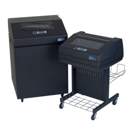
The Printronix P7000™ Line Matrix Printing Platform extends the series of technology innovations that cement Printronix’s leadership position. Line matrix printing is Printronix’s flagship technology, and it remains the... - Page 12 Chapter Printer Overview There are three printer configurations: Enclosed Cabinet (P72XX) • The enclosed cabinet models provide for near silent operation, making these printers perfectly suitable for use in the quietest of office environments. • Provides the best paper handling for large print runs. All paper input and output is contained inside the cabinet and protected from bumping and contamination.
-
Page 13: Consumable Monitoring With Printnet Enterprise
Consumable Monitoring With PrintNet Enterprise The Integrated Print Management System works with PrintNet Enterprise (PNE). PNE allows a system administrator to remotely view the current consumable status of all printers. PNE can be configured to deliver alerts on all consumable warnings. When a ribbon reaches the low state, PNE notifies the system administrator remotely via an automated e-mail alert of the low condition. -
Page 14: Warnings And Special Information
External Network Interface Card User’s Manual — Information about network protocols, configuration, and operation. • IGP/PGL Programmer's Reference Manual — Provides information used with the optional IGP Printronix emulation enhancement feature. • IGP/VGL Programmer's Reference Manual — Provides information used with the optional Code V emulation enhancement feature. -
Page 15: Contact Information
Asia Pacific (65) 6548 4114 China (86) 800-999-6836 http://www.printronix.com/public/servicessupport/default.aspx Printronix Supplies Department Contact the Printronix Supplies Department for genuine Printronix supplies. Americas (800) 733-1900 Europe, Middle East, and Africa 33 (0) 1 46 25 19 07 Asia Pacific (65) 6548 4116... -
Page 16: Corporate Offices
Phone: (65) 6542 0110 Fax: (65) 6546 1588 Printronix Commercial (Shanghai) Co. Ltd 22F, Eton Building East No.555, Pudong Av. Shanghai City, 200120, P R China Phone: (86) 400 886 5598 Fax: (86-21) 5138 0564 Visit the Printronix web site at www.printronix.com... -
Page 17: Setting Up The Printer
Setting Up The Printer Before You Begin Read this chapter carefully before installing and operating the printer. The printer is easy to install. However, for your safety and to protect valuable equipment, perform all the procedures in this chapter in the order presented. Power Requirements The printer must be connected to a power outlet that supplies 88 to 270 volts AC. -
Page 18: Printer Dimensions
Chapter Printer Dimensions Table 1. Maximum Interface Connection Cable Length Interface Type Maximum Cable Length Centronics Parallel 5 meters (15 feet) Dataproducts Parallel 12 meters (40 feet) IEEE 1284 Parallel 10 meters (32 feet) Serial RS-232 15 meters (50 feet) Serial RS-422 1220 meters (4000 feet) Coax... - Page 19 59.0 in (149.9 cm) 42.5 in (107.8 cm) 27.0 in (68.6 cm) 32.5 in 83.0 in 27.0 in (82.6 cm) (210.8 cm) (68.6 cm) 27.0 in 32.0 in (68.6 cm) (81.3 cm) Figure 2. Printer Dimensions - Cabinet Model with Paper Stacker...
- Page 20 Chapter Printer Dimensions 25 in. (63.5 cm) 10.5 in. (26.67 cm.) 48.0 in. (122 cm) 30 in. (76.2 cm.) 24.6 in. (62.48 cm) Figure 3. Printer Dimensions - Pedestal Model...
-
Page 21: Printer Component Locations
Printer Component Locations Printer Component Locations Ribbon Ribbon Cartridge Tab (2) Ribbon Tension Knob Tractor (2) Blue Tractor Lock (2) Splined Shaft Hammer Bank Cover and Paper Ribbon Mask Support (2) Slot (2) Vertical Position Knob Platen Lever Platen Stop Ribbon Cartridge Interface 183871 REV A... - Page 22 Chapter Printer Component Locations...
-
Page 23: Operating The Printer
Operating The Printer Powering On The Printer When you power on the printer, it executes a self-test. The default power-up state is online. When the self-test completes and the software has initialized successfully, the status indicator light turns on, indicating the printer is online. The default value of the type of emulation you have installed appears in the upper right corner of the display. -
Page 24: The Control Panel
Chapter The Control Panel The Control Panel Figure 5 shows the keys, displays, and indicators as they appear on the control panel. The following section provides the descriptions, and functions of the control panel keys. Key combinations are indicated with the plus (+) sign. For example, “Press ”... - Page 25 In offline mode, this key cancels all data in the print buffer, if enabled in the “ADVANCED USER - P7000” menu (see page 225). The print buffer is cleared without printing any of the data and the current paper position is set as the top-of-form.
- Page 26 Chapter The Control Panel SET TOF Sets the top-of-form on the printer. This key is active only when the printer is offline and will not operate if the printer is in a fault condition. The paper moves down to the print position and aligns to the top-of-form. Refer to the Quick Setup Guide for complete instructions on how to set the top-of-form.
- Page 27 Control Panel Keys > UP + DOWN ( Locks and unlocks the ENTER key. NOTE: The ENTER key lock and unlock function can be configured to be a > key combination other than (see page 230). < PREV or NEXT ( Moves between the options on the current level of configuration menu.
-
Page 28: Cancel A Print Job
3. Press CANCEL). NOTE: You may need to enable the Cancel option on the front panel. See “ADVANCED USER - P7000” on page 225 for details. 4. Set the top-of-form. Refer to the Quick Reference Guide. -
Page 29: Operational Procedures
Reload Paper Operational Procedures This section contains routine printer operating procedures on how to: • reload paper • unload paper Reload Paper Do this procedure when “LOAD PAPER” displays. (This message occurs when the last sheet of paper passes through the paper slot.) This procedure reloads paper without removing the last sheet of the old paper supply, while retaining the current top-of-form setting. - Page 30 Chapter Operational Procedures New Paper Existing Paper Figure 7. Loading New Paper into the Printer 6. Pull the new paper above and behind the ribbon mask, but in front of the existing paper. See Figure 4 on page 21 for the ribbon mask location. If necessary, gently press the existing paper back.
- Page 31 Reload Paper Vertical Position Knob Paper Thickness Indicator Platen Stop Platen Lever Platen Stop Knob 183444 REV B Figure 8. Setting the Platen Lever 9. Turn the platen stop knob clockwise or counterclockwise to match the paper thickness. (The A-B-C scale corresponds approximately to 1-, 3-, and 6-part paper thickness).
- Page 32 Chapter Operational Procedures Wire Guide (2) Paper Paper Slot Slot Metal Paper Guide (P7220 and P7200HD) Cabinet Model Pedestal Model 183439 REV B 183440 REV B Figure 9. Paper Slots on the Printers NOTE: Perform steps 15 to 32 only if you are unable to load the new paper over the existing paper.
- Page 33 Reload Paper Left Tractor Door Paper Left Tractor Lock Figure 10. Loading Paper on the Left Tractor 18. Pull the paper above and behind the ribbon mask. See Figure 4 on page 21 for the ribbon mask location. 19. Load the paper on the left tractor. 20.
- Page 34 Chapter Operational Procedures Tractor Paper Tractor Splined Shaft Tractor Lock Paper Scale Figure 11. Positioning the Left Tractor to Avoid Damage CAUTION To avoid damage to the printer caused by printing on the platen, always position the left tractor unit directly to the left of the “1” mark on the paper scale.
- Page 35 Reload Paper Tractor Door Tractor Lock Figure 12. Loading Paper onto the Sprockets 22. Unlock the right tractor. 23. Load the paper onto the sprockets and close the tractor door. If necessary, slide the right tractor to remove paper slack or to adjust for various paper widths.
- Page 36 Chapter Operational Procedures 24. Pedestal models: Using the vertical position knob to move the paper up, guide the paper over the upper paper guide and through the slot to the rear of the top cover. For pedestal models with the Quick Access Cover, refer to the Quick Setup Guide for paper exiting options.
- Page 37 Reload Paper Vertical Position Knob Paper Thickness Indicator Platen Stop Platen Lever Platen Stop Knob 183444 REV B Figure 15. Adjusting the Platen Lever 28. Turn the platen stop knob clockwise or counterclockwise to match the paper thickness. (The A-B-C scale corresponds approximately to 1-, 3-, and 6-part paper thickness.
-
Page 38: Unload Paper
Chapter Operational Procedures Unload Paper 1. Press ON LINE/CLEAR to place the printer in offline mode and open the printer cover. 2. For cabinet models, open the cabinet rear door. For models with the power stacker installed, press the STACKER UP key on the rear control panel. - Page 39 Unload Paper Paper Power Stacker Figure 17. Removing Stacked Paper from the Printer 6. For cabinet models, remove the stacked paper from the rear cabinet floor. For cabinet models with the power stacker installed, remove the paper from the wire paper tent and press the STACKER DOWN key to lower the stacker mechanism.
- Page 40 Chapter Operational Procedures Tractor Door Platen Lever Figure 18. Completely Removing the Paper 8. To completely remove the paper from the printer: a. Raise the platen lever as far as it will go and open both tractor doors. CAUTION Be careful when pulling any paper backward through the paper path, especially when using a label stock.
-
Page 41: Integrated Print Management System
(the cartridge) and feeds only in one direction. The CRS contains an interface board that allows communication between the printer and the cartridge. Using the CRS, the P7000 automatically detects when a new or used ribbon is installed and determines the ribbon’s length, ink color, and expected yield. -
Page 42: Loading A Used Ribbon Cartridge
System is factory set so that the image quality at the end of the ribbon life is as good as it was when the ribbon was new. You may adjust the ribbon end point for a lighter or darker image as required for your printing needs. See “PRINTER CONTROL - P7000” on page 221. -
Page 43: Changing Ribbon Cartridge
Changing Ribbon Cartridge Changing Ribbon Cartridge Before changing the ribbon cartridge, determine whether at the end of ribbon life if you want to make the print lighter (extend the ribbon life) or darker (shorten the ribbon life). If you want to make the print lighter or darker, go to “Ribbon End Point”... - Page 44 Chapter Integrated Print Management System Ribbon Tab (2) Ribbon Cartridge Ribbon Tension Knob Tab Slot (2) Air Shroud Assembly Figure 20. Installing the Ribbon Cartridge 5. Remove the ribbon slack on the new ribbon cartridge by turning the ribbon tension knob clockwise. CAUTION Do not turn the ribbon tension knob counterclockwise.
- Page 45 Changing Ribbon Cartridge Ribbon Cartridge Ribbon Mask Hammerbank Cover Ribbon Ribbon Tension Knob Ribbon Cartridge Figure 21. The Ribbon Cartridge Snapped in Place 7. Rock the cartridge downward, making sure that the ribbon goes between the guide and the mask (see Figure 21). You will feel it snap into place. CAUTION Make sure that the ribbon does not twist or fold over.
- Page 46 Chapter Integrated Print Management System...
-
Page 47: The Configuration Menus
The Configuration Menus Configuration Overview To print data, the printer must respond correctly to signals and commands received from the host computer. Configuration is the process of matching the printer's operating characteristics to those of the host computer and to specific tasks, such as printing labels or printing on different sizes of paper. -
Page 48: Default And Custom Configurations
Chapter Configuration Overview Default And Custom Configurations A configuration consists of a group of parameter settings, such as line spacing, forms length, etc. Your printer provides a fixed default configuration and allows you to define several custom configurations for use with particular print jobs. -
Page 49: Changing Parameters Example
Changing Parameters Example Changing Parameters Example * = Factory Default OFFLINE QUICK PRINTER . . . SETUP CONTROL Ribbon End Open Platen Barcode Tear Bar Point @ BOF Quality Dist. Darker +6 Disable* Dark* 7.46 in.* Darker +5 Enable Draft (4.5-10.5 in.) Darker +4 Darker +3... - Page 50 Chapter Configuration Overview Step Press Notes Make sure the printer is on. OFFLINE ON LINE/CLEAR QUICK SETUP ENTER SWITCH Allows you to make configuration changes. UNLOCKED OFFLINE QUICK SETUP OFFLINE PRINTER CONTROL UNTIL PRINTER CONTROL Ribbon End Point PRINTER CONTROL Barcode Quality UNTIL Barcode Quality...
- Page 51 Changing Parameters Example Step Press Notes PRINTER CONTROL Display Language UNTIL Display Language English* Display Language Press until the desired parameter displays. Spanish Display Language The * indicates this choice is active. ENTER Spanish* ENTER SWITCH Locks the ENTER key. LOCKED ENTER = Save Press ENTER to automatically save...
-
Page 52: Auto Save Configuration
Chapter Configuration Overview Auto Save Configuration After any changes are made to the Factory Default configuration menu items, you will be prompted to save the changes to “Config #” when you place the printer online. “#” represents the next available unassigned configuration number. - Page 53 Saving Your New Configuration Example 1 This example shows how to save a configuration as a numbered configuration, then later print it. Step Press Notes Make sure the printer is on. OFFLINE ON LINE/CLEAR QUICK SETUP ENTER SWITCH Allows you to make configuration changes. UNLOCKED OFFLINE QUICK SETUP...
- Page 54 Chapter Configuration Overview Step Press Notes NOTE: We recommend that you print the configuration. To print the configuration go to Step 9. To skip this procedure and resume printer operation, go to Step 14. CONFIG. CONTROL Save Config. CONFIG. CONTROL Print Config.
- Page 55 Saving Your New Configuration Example 2 This example shows how to save a configuration as a named configuration. Step Press Notes Make sure the printer is on. OFFLINE ON LINE/CLEAR QUICK SETUP ENTER SWITCH Allows you to make configuration changes. UNLOCKED OFFLINE QUICK SETUP...
- Page 56 Chapter Configuration Overview Step Press Notes Saves the first character. Cycle through the choices until “E” displays. UNTIL Saves the second character. Cycle through the choices until “S” displays. UNTIL Saves the third character. TES_ Cycle through the choices until “T” displays. TEST UNTIL Saves the fourth character.
-
Page 57: Optimizing Print Quality
Optimizing Print Quality Step Press Notes Save Config. TEST now appears as one of configuration TEST choices. Saving Configuration ENTER Save Config. Your configuration is saved as TEST. TEST* ENTER SWITCH Locks the ENTER key. LOCKED ONLINE ON LINE/CLEAR Ribbon Life = 100% Now you have the saved configuration for later use if needed. -
Page 58: Optimizing Print Speed
Chapter Configuration Overview Optimizing Print Speed LP+, IGP/PGL, and IGP/VGL Emulations The printer has been configured at the factory for optimal print speed. To optimize print quality instead, you can change values for specific configuration parameters such as Barcode Quality and Print Quality. Doing so, however, will decrease the printer speed. -
Page 59: P7000 Crp Main Menu
Not available if PNE Port number is set to Serial. If Real Time Clock (RTC) option is installed. Available for Zero Tear Pedestal printer only. Only if a Cisco radio card is installed. Figure 22. P7000 CRP Main Menu Configuration... - Page 60 Chapter P7000 CRP Main Menu ACTIVE Active EMULATION PRINTER ADVANCED 5, 6, 7 IGP EMUL Emulation CONTROL USER page 105 page 106 page 106 page 221 page 225 IGP/PGL* 44/48XX-ANSI CTHI Ribbon End Point Ptx Setup Option IGP/VGL PCL-II LinePrinter+...
-
Page 61: P7000Hd Crp Main Menu
P7000HD CRP Main Menu * = Factory Default If installed. OFFLINE QUICK CONFIG. HOST NETWORK PRINTER SETUP CONTROL INTERFACE SETUP CONTROL page 64 page 72 page 74 page 89 page 222 Host Interface Load Config. IEEE 1284 Adapter Address Open Platen @ BOF Load Config. - Page 62 Chapter P7000HD CRP Main Menu Brief descriptions follow for the first-level configuration menu options: • QUICK SETUP — These options allow quick access to the most frequently changed or inputted parameters during the installation of the printer. • ZTP SETTINGS These options allow you to set parameters for zero tear pedestal printers.
-
Page 63: Quick Setup - P7000
QUICK SETUP - P7000 QUICK SETUP (from page 59) Host Device ID Adapter Ethernet WLAN Interface Address Address Address Auto Switching* IPDS* IP Address IP Address IP Address Centronics 5225 Subnet Mask Subnet Mask Subnet Mask Dataproducts 4234-2 Gateway Address... -
Page 64: Quick Setup - P7000Hd
Chapter QUICK SETUP - P7000HD QUICK SETUP (from page 63) Form Vert Horiz Page Length Max Line Width Forms Forms Width Funct. of CPI Bot. Frm 66/6* Left Mrg 0.00* Inches/Page* 13.2 Inches* 136 Characters* (0-198) (0-198) Lines/Page 13.6 Inches (1-272) Top Mrg 0/6* Top Mrg 0/6*... -
Page 65: Host Interface
Host Interface The Host Interface menu enables you to select and configure interfaces between the printer and your host computer. Device ID This parameter defines the printer emulation as IPDS, 4234-2 or 5225. After the emulation has been changed, a POR status is sent to the host. IPDS is the default. -
Page 66: Wlan Address
Chapter QUICK SETUP - P7000HD WLAN Address • IP Address. A numeric address such as 123.45.61.23 which identifies a printer or server in a LAN or WAN. • Subnet Mask. A binary value used to divide IP networks into smaller subnetworks or subnets. -
Page 67: Form Length
PGL SFCC You can specify which hex code (1-FF) will be used as the Special Function Control Character (SFCC). The SFCC denotes that the following data is an IGP command. • 7E (the default) • 1 – FF VGL SFCC You can specify which hex code (1-FF) will be used as the Special Function Control Character (SFCC). - Page 68 Chapter QUICK SETUP - P7000HD P-Series SFCC This parameter allows you to select which ASCII codes will function as the Special Function Control Code (SFCC) command delimiter. P-Series codes can use hex 00 through hex 7F. Options include the following: •...
- Page 69 Vert Forms • Bot Frm 66/6 (default). This option sets the bottom margin for the forms. You must specify the bottom margin in lines (at 6 lines per inch), ranging from 0 to 198 lines (33 inches). The default setting is 66. Press the right arrow to increase the value, left arrow to decrease the value, and ENTER to change units.
-
Page 70: Ztp Settings
Chapter ZTP SETTINGS Ribbon End Point This parameter adjusts the point at which the system will declare the ribbon as being expended. The life count will always be from 100% to 0%, but if a darker setting is selected 0% will be reached more quickly. If a lighter setting is selected, the system will extend the time it takes to reach 0%. -
Page 71: Config. Control- P7000
CONFIG. CONTROL- P7000 The CONFIG. CONTROL menu allows you to control your printer’s configurations according to the specifications necessary for your print jobs. CONFIG. * = Factory Default CONTROL (from page 59) Load Save Print Delete Power-Up Protect Config. Config. -
Page 72: Config. Control - P7000Hd
Chapter CONFIG. CONTROL - P7000HD CONFIG. CONTROL - P7000HD The CONFIG. CONTROL menu allows you to control your printer’s configurations according to the specifications necessary for your print jobs. * = Factory Default CONFIG. CONTROL (from page 61) Load Save Print Delete Power-Up... -
Page 73: Power-Up Config
Power-Up Config. You can specify which of the nine configurations (Factory or 1-8) will be the power-up configuration. Protect Configs. You can specify whether or not a new configuration should overwrite an existing configuration when you activate the Save Configs. parameter. When disabled (default), the new configuration will overwrite the existing configuration. -
Page 74: Host Interface - P7000
Chapter HOST INTERFACE - P7000 HOST INTERFACE - P7000 * = Factory Default HOST If installed INTERFACE (from page 59) Auto Twinax Coax IEEE 1284 Centronics Dataproducts Switching* (Available with (Available with (see page 77) (see page 78) (see page 81) -
Page 75: Auto Switching Submenu
Auto Switching Submenu IMPORTANT When switching between Twinax, Coax, or Auto Switching, the printer will load the power-up configuration and the new interface parameters. Any settings made and not saved before selecting these interfaces will be lost. Auto Switching Submenu * = Factory Default Auto Switching If Installed... -
Page 76: Port Type
Chapter HOST INTERFACE - P7000HD Port Type Select the types of parallel, serial and/or C/T interfaces which are connected to the printer. For example, if your printer is attached to one host with a Centronics connection and a second host with an RS-422 serial connection, you would select Centronics under the Parallel Hotport menu, RS-422 under the Serial Hotport menu, and Disable under the C/T Hotport menu. -
Page 77: Ieee 1284 Parallel (Bidirectional) Submenu
IEEE 1284 Parallel (Bidirectional) Submenu IEEE 1284 Parallel (Bidirectional) Submenu * = Factory Default IEEE 1284 (from page 74) Prime Buffer Size Auto Trickle Offline Signal Action in K Trickle Time Process Enable* Reset* Disable* 1/4 sec* Disable* Disable Do Nothing 1-16 Enable 1/2 sec... -
Page 78: Centronics (Parallel) Submenu
Chapter HOST INTERFACE - P7000HD Trickle Time When the printer is printing data from a host and a second job is received by the printer from a different host, Trickle Time prevents the second host from timing out while it is waiting for its data to be printed. In order to support this feature, the port has to be able to accept data from the host and store it for future use. -
Page 79: Data Polarity
Centronics (Parallel) Submenu Data Bit 8 • Enable (default). Allows access to the extended ASCII character set. • Disable. The printer interprets bit 8 of each incoming data character as a zero, regardless of its actual setting. PI Ignored The PI (Paper Instruction) signal is used to control vertical paper motion. •... -
Page 80: Trickle Time
Chapter HOST INTERFACE - P7000HD TOF Action • Reset (default). A form feed is performed before a warm start when the prime signal is asserted from the host. This setting is used only if the prime signal parameter is enabled. •... -
Page 81: Dataproducts Submenu
Dataproducts Submenu Dataproducts Submenu * = Factory Default Dataproducts (from page 74) Data Bit 8 PI Ignored Data Resp. Latch Data Prime Signal Polarity Polarity Enable* Enable* Standard* Standard* Middle* Disable* Disable Disable Inverted Inverted Trailing Enable Leading TOF Action Buffer Size Auto Trickle... - Page 82 Chapter HOST INTERFACE - P7000HD Resp. Polarity The Response Polarity parameter must be set to match the response polarity of your host computer. • Standard (default). Does not invert the response signal. • Inverted. Inverts the response signal sent to the host computer. Latch Data On Specifies whether the data is read on the leading, middle, or trailing edge of the data strobe signal.
-
Page 83: Serial Submenu
Serial Submenu Trickle Time When the printer is printing data from a host and a second job is received by the printer from a different host, Trickle Time prevents the second host from timing out while it is waiting for its data to be printed. In order to support this feature, the port has to be able to accept data from the host and store it for future use. -
Page 84: Interface Type
Chapter HOST INTERFACE - P7000HD Interface Type This parameter allows you to select either the RS-232 or RS-422 serial port interface. The default is RS-232. Data Protocol You can select one of the following serial interface protocols to meet the host interface requirements. -
Page 85: Baud Rate
Serial Submenu The response characters are described in Table 2. Table 2. Series1 1 Char Response Characters Printer State Response Online and Buffer Empty Online and Buffer Full Offline and Buffer Empty Offline and Buffer Full • SERIES1 2 CHAR. This protocol behaves exactly the same as the Series1 Char except there is a two-character response to the host. -
Page 86: Word Length
Chapter HOST INTERFACE - P7000HD Word Length Sets the length of the serial data word. The length of the data word can be set to 7 or 8 bits, and must match the corresponding data bits setting in the host computer. -
Page 87: Framing Errors
Serial Submenu Poll Character This option is for the Series1 protocol. Whenever the printer receives this character, it sends a response to the host indicating the current state of the printer (see Series1 protocol). It may be configured from 0 through FF hexadecimal. -
Page 88: E-Net Adapter Submenu
Chapter HOST INTERFACE - P7000HD E-Net Adapter Submenu * = Factory Default E-Net Adapter (from page 74) Buffer Size in K 1-16 The E-Net Adapter interface allows you to locate the printer on a LAN rather than attach the host directly into the printer. The detailed configuration of this option is given in the PrintNet User's Manual. -
Page 89: Network Setup Menu - P7000
Ethernet Submenu NETWORK SETUP MENU - P7000 NETWORK SETUP (from page 59) ADAPTER ADAPTER ETHERNET ETHERNET WLAN ADDRESS PARAMS ADDRESS PARAMS ADDRESS See page 90. See page 91. See page 94. See page 95. See page 97. WLAN WLAN WLAN... -
Page 90: Adapter Address
Chapter NETWORK SETUP MENU - P7000HD ADAPTER ADDRESS * = Factory Default ADAPTER ADDRESS (from page 89) DHCP IP Address Subnet Gateway Mask Address Address Disable* xxx.xxx.xxx.xxx xxx.xxx.xxx.xxx xxx.xxx.xxx.xxx hhhhhhhhhhhh Enable IP Address A numeric address such as 123.45.61.23 which identifies a printer or server in a LAN or WAN. -
Page 91: Adapter Params
ADAPTER PARAMS ADAPTER PARAMS ADAPTER * = Factory Default PARAMS (from page 89) Novell Nest Serv NetBIOS Novell ASCII IPDS Protocol Type Protocol Frame Data Port Data Port Enable* Auto* Enable* Ethernet 802.2* 9100* 5001* Disable Bindery Disable 802.2 Snap 1023 - 65535 1023-65535 Auto Sensing... -
Page 92: Novell Protocol
Chapter NETWORK SETUP MENU - P7000HD Novell Protocol This option determines whether the Novell protocol will be available. The selections are as indicated below: • Enable (default). Makes the Novell protocol available with the ethernet installed. • Disable. Makes the Novell protocol unavailable during printer operation. Nest Serv Type You can change the Nest Server using this option, but consult your administrator for the appropriate setting. -
Page 93: Keep Alive Timer
ADAPTER PARAMS Keep Alive Timer This is the time that the Keep Alive Timer will run. With the Keep Alive Timer on, the tcp connection will stay connected even after the print job has terminated. • 3 Minutes (default) • 2 - 10 Minutes Ethernet Speed This menu option only appears if a 10/100Base-T network interface card... -
Page 94: Ethernet Address
Chapter NETWORK SETUP MENU - P7000HD ETHERNET ADDRESS * = Factory Default ETHERNET ADDRESS (from page 89) IP Address Subnet Gateway DHCP Mask Address Address xxx.xxx.xxx.xxx xxx.xxx.xxx.xxx xxx.xxx.xxx.xxx hhhhhhhhhhhh Disable* Enable IP Address A numeric address such as 123.45.61.23 which identifies a printer or server in a LAN or WAN. -
Page 95: Ethernet Params
ETHERNET PARAMS ETHERNET PARAMS ETHERNET * = Factory Default PARAMS (from page 89) NetBIOS ASCII IPDS Data Keep Alive Ethernet Job Control Protocol Data Port Port Timer Speed Enable* 9100* 5001* 3 Minutes* Auto Select* Standard* Disable Enhanced 1023 - 65535 1023 - 65535 2 - 10 Minutes 10 Half Duplex... - Page 96 Chapter NETWORK SETUP MENU - P7000HD Ethernet Speed This menu option only appears if a 10/100Base-T network interface card (NIC) is installed. The Ethernet Speed menu allows compatibility with different systems and networks. The factory default is Auto Select. • Auto Select.
-
Page 97: Wlan Address
WLAN ADDRESS WLAN ADDRESS * = Factory Default WLAN ADDRESS (from page 89) DHCP IP Address Subnet Gateway Mask Address Address Disable* xxx.xxx.xxx.xxx xxx.xxx.xxx.xxx xxx.xxx.xxx.xxx hhhhhhhhhhhh Enable IP Address A numeric address such as 123.45.61.23 which identifies a printer or server in a LAN or WAN. -
Page 98: Wlan Params
Chapter NETWORK SETUP MENU - P7000HD WLAN PARAMS * = Factory Default Only when 40 Bites is selected Only when 128 Bits is selected Only when a Symbol radio card is installed. Only when a Cisco radio card is installed. WLAN Read only PARAMS... -
Page 99: Signal Strength
WLAN PARAMS Signal Strength This menu displays the strength of the wireless signal. NOTE: This is a display value only and cannot be changed. Operation Mode Allows you to select the way the Wireless option communicates: • Infrastructure (default). The Wireless option must go through a server. •... -
Page 100: Power Mgmt
Chapter NETWORK SETUP MENU - P7000HD Ant. Diversity The type of antenna used: • Diverse (default). Select when you want to use the antenna with the best reception. • Primary. Select when you want to use the Primary antenna on the server. •... -
Page 101: Default Wep Key
WLAN PARAMS Auth Method This feature allows the user to select the authentication method used for the wireless network interface. • Open (default). Selects open authentication. • Shared. Selects shared key authentication. • Kerberos. Selects Kerberos authentication (for use when a Symbol RF card is installed). -
Page 102: Wlan Kerberos
Chapter NETWORK SETUP MENU - P7000HD WPA Cipher Selects the WPA wireless security cipher setting. Options include: • TKIP (default) • • TKIP+AES WPA P-Phs Allows you to set the individual bytes of the WPA passphrase. Reset WPA P-Phs Allows you to reset all 32 bytes of the WPA passphrase at once. WLAN KERBEROS * = Factory Default WLAN... -
Page 103: Kdc Port Number
WLAN KERBEROS Kerb. Passwd • Kerb. Pwd (01-15). The first 15 characters of the Kerberos password (maximum number of characters is 40). • Kerb. Pwd (16-30). Characters 16 to 30 of the Kerberos password (maximum number of characters is 40). •... -
Page 104: Wlan Leap
Chapter NETWORK SETUP MENU - P7000HD WLAN LEAP * = Factory Default WLAN Only if a Symbol radio card is installed. LEAP Only if a Cisco radio card is installed. (from page 89) Auth Method LEAP Reset LEAP LEAP Reset LEAP Username User Password... -
Page 105: Active Igp Emul
IMPORTANT To configure an IGP emulation, the IGP emulation must be selected in the ACTIVE IGP EMUL menu. The IGP emulation that is not selected will not appear in the EMULATION menu (see “P7000 CRP Main Menu” on page 59). -
Page 106: Active Emulation
Chapter ACTIVE EMULATION ACTIVE EMULATION The ACTIVE EMULATION menu allows you to activate the desired emulation to be used with your printer. If installed If ANSI is installed If LG is installed If PCL-II is installed ACTIVE 2, 3, 4 EMULULATION (from page 60) 44/48XX-ANSI... -
Page 107: Coax/Twinax (Cthi) Emulation
Standard Coax/Twinax (CTHI) Emulation * = Factory Default Coax/Twinax EMULATION Host Interface (from page 106) CTHI Standard* Simp Prot Conv Coax Twinax 3270 5250 SPC Coax SPC Twinax Params Params Params Params Params Params page 109 page 118 page 124 page 131 page 135 page 138... -
Page 108: Simple Prot Conv
Chapter Coax/Twinax (CTHI) Emulation Simple Prot Conv The Simple Protocol Converter (SPC) option allows those who use third party add-on Coax or Twinax protocol converters to produce the same output on a Line Matrix printer with the Coax/Twinax (CTHI) capability as done using a non-CT printer with the third party converter interfaces. -
Page 109: Coax Emulation
Coax Emulation Coax Emulation * = Factory Default CTHI Valid only when the printer (from page 107) emulates 3287. Standard* Coax Params Char Set Translation Active Char Prt Partial Select Line (see page 110) Secondary Set* Enable* Primary Set Disable Buffer Early Print SCS Buffer... - Page 110 Chapter Coax/Twinax (CTHI) Emulation * = Factory Default Char Set Select (from page 109) Primary Secondary Sets Sets 0037 English US* English US* 0037 Eng Nether English UK 0285 English UK Austrian/German 0273 Austr/Germ German (Alt) 0274 Belg. Old Belgian 0275 Brazilian Brazilian 0260 Canad Fren...
-
Page 111: Translation Tbl
Coax Emulation * = Factory Default Compatibility (from page 109) CR At NL At Position Aft FF Last Char = FF Null FF Validity MPP+1 MPP+1 (4234 only) Suppression Off* Off* Off* Auto Skip FF After Job CR, EM & NL At End (3287 only) Off*... -
Page 112: Buffer Reprint
Chapter Coax/Twinax (CTHI) Emulation PA2 is only valid when the printer is in the Offline state and the coax SCS data stream is active. This function displays the “PA2 ENABLED” message when the ENTER key is pressed and sends a special operator request to the host when the printer is put back in online mode. -
Page 113: Change Case
This option is used in Twinax SPC emulation. The range is ASCII character. This option allows users to define ther own lead-in characters for the Printronix Specific commands. Select a hex value for the following codes for the User Defined option: •... -
Page 114: Set Text Orientn
Chapter Coax/Twinax (CTHI) Emulation Set Text Orientn Specifies the direction in which characters are printed on the page. This allows the printer to print languages which are printed right to left instead of left to right. • Control By Host (default). Allows printers configured as a 4234 to use the “Set Text Orientation”... - Page 115 Coax Emulation Position Aft FF (4234 only) Allows you to select the location of the print position after a form feed command is sent. • On (default). Sets the printer to print at print position 1 of the first print line on the next form.
-
Page 116: Translate Table
Chapter Coax/Twinax (CTHI) Emulation FF After Job Determines the print position after an operator-initiated local copy (print screen function). • Off (default). Performs an automatic new line command after completing a print buffer (unless a new line, form feed, or carriage return command was the last one executed). -
Page 117: Buffer Print
Coax Emulation Max. Print Width Set the maximum print width at either 13.2 inches or the maximum width of the printer. The default is 13.2 inches. Buffer Print • Disable (default). The printer will print normally. • Enable. The printer prints the EBCDIC data and control codes received from the host as hex values. -
Page 118: Twinax Params
Chapter Coax/Twinax (CTHI) Emulation Twinax Params * = Factory Default CTHI (from page 107) Standard* Twinax Params Char Set Active Char Prt Partial Device ID Device 5225 World Select Line Address Trade (see page 119) Secondary Set* Enable* IPDS* Address 1* Standard Char* Primary Set Disable... - Page 119 Twinax Params * = Factory Default Char Set Select (from page 118) Primary Secondary Sets Sets 0037 English US* English US* 0037 Eng Nether Austrian/German 0500 Swiss Bil Belgian 0500 Belg. New Brazilian 0273 Austr/Germ Canadian French 0274 Belg. Old Danish/Norweg.
-
Page 120: World Trade
Chapter Coax/Twinax (CTHI) Emulation Char Set Select Specifies the print language used by the printer. Character sets are shown in detail in the Character Sets Reference Manual. Active Char Set This option selects which group of character sets (Primary or Secondary) will be active. - Page 121 This option is used in Twinax SPC emulation. The range is ASCII character. This option allows users to define ther own lead-in characters for the Printronix Specific commands. Select a hex value for the following codes for the User Defined option: •...
-
Page 122: Lac Option
Chapter Coax/Twinax (CTHI) Emulation Graphic Chek Cod Specifies the replacement character to print in place of any unprintable character that is received from the host. Choose a hex character from 40 through FE. The character becomes the printer default when: •... -
Page 123: Format Control
Twinax Params Format Control Enables the printer to reflect the same spacing as CTPC model printers after absolute and relative move commands are executed. • Disable (default). Reflects distance, generated by the IGP/VGL feature, IGP/PGL feature, and Hex Transparent control code sequence, in the new position (after absolute and relative move commands are executed). -
Page 124: Params
Chapter Coax/Twinax (CTHI) Emulation 3270 Params * = Factory Default 3270 This menu appears only if the TN3270 option is installed. Params (from page 107) Char Set Translation Active Char Prt Partial Early Print Transparent Select Line Cmpl Lead-in Chars (see page 125) Secondary Sets* Enable*... -
Page 125: 3270 Params
3270 Params 3270 * = Factory Default Params Char Set Select (from page 124) Primary Sets Secondary Sets 0037 English US* English US* 0037 Eng Nether English UK 0285 English UK Austrian/German 0273 Austr/Germ German (Alt) 0274 Belg. Old Belgian 0275 Brazilian Brazilian 0260 Canad Fren... - Page 126 Chapter Coax/Twinax (CTHI) Emulation Translation Tbl Prints out a table of the Coax interface’s current character set. This operation is valid only when the TN3270 interface is the current interface. Active Char Set Specifies which character language set will be the active set. •...
- Page 127 This option is used to set user defined lead-in characters. The range is ASCII character. This option allows users to define ther own lead-in characters for the Printronix Specific commands. Select a hex value for the following codes for the User Defined option: •...
-
Page 128: Last Char = Ff
Chapter Coax/Twinax (CTHI) Emulation Compatibility Op The Compatibility Options allow you to select special printer functions in the non-SCS mode based on the capabilities of the printer emulated. CR At MPP+1 MPP is Maximum Print Position, which is also known as line length. This option controls a carriage return at the end of a print line and at MPP+1. -
Page 129: Ff After Job
3270 Params FF Validity Determines if the position of a form feed command affects its execution. • Off (default). Performs a form feed only if it occurs at the first print position in a line or at Maximum Print Position +1. A form feed command at any other position is recognized as a space. - Page 130 Chapter Coax/Twinax (CTHI) Emulation Format Control Enables the printer to reflect the same spacing as CTPC model printers after absolute and relative move commands are executed. • Disable (default). Reflects distance, generated by the VGL feature, PGL feature, and Hex Transparent control code sequence, in the new position (after horizontal and vertical tabs are executed).
-
Page 131: 5250 Params
5250 Params 5250 Params * = Factory Default 5250 This menu appears only if the TN5250 option is installed. Params (from page 107) Graphic Char Set Translation Active Char Prt Partial Transparent Chek Err Select Line Enable* Lead-in Chars (see page 132) Secondary Set* Enable* Disable... - Page 132 Chapter Coax/Twinax (CTHI) Emulation * = Factory Default 5250 Params Char Set Select (from page 131) Primary Sets Secondary Sets English US* 0037 English US* Austrian/German 0037 Eng Nether Belgian 0500 Swiss Bil Brazilian 0500 Belg. New Canadian French 0273 Austr/Germ Danish/Norweg.
- Page 133 This option is used to set user defined lead-in characters. The range is ASCII character. This option allows users to define ther own lead-in characters for the Printronix Specific commands. Select a hex value for the following codes for the User Defined option: •...
- Page 134 Chapter Coax/Twinax (CTHI) Emulation Graphic Chek Err Allows overriding of the host setting for the SGEA (Set Graphic Error Action) command. For more information about the SGEA command, refer to the Coax/Twinax Programmer's Reference Manual. • Enable (default). The host setting for the SGEA used by the printer. If the SGEA command is requested to stop on graphic errors, the printer will stop when a graphic error is detected.
-
Page 135: Spc Coax Params
SPC Coax Params Format Control Enables the printer to reflect the same spacing as CTPC model printers after absolute and relative move commands are executed. • Disable (default). Reflects distance, generated by the VGL feature, PGL feature, and Hex Transparent control code sequence, in the new position (after horizontal and vertical tabs are executed). -
Page 136: Logical Buf Size
This option is used in Twinax SPC emulation. The range is ASCII character. This option allows users to define ther own lead-in characters for the Printronix Specific commands. Select a hex value for the following codes for the User Defined option: •... -
Page 137: Spc Null Supp
SPC Coax Params PA2 is only valid when the printer is in the OFFLINE state and the Coax SCS data stream is active. This function displays the “PA2 ENABLED” message when the ENTER key is pressed and sends a special operator request to the host when the printer is placed ONLINE. -
Page 138: Spc Twx Params
Chapter Coax/Twinax (CTHI) Emulation SPC Twx Params * = Factory Default CTHI (from page 107) Simp Prot Conv SPC Twinax Params Device SPC Type Translation Buffer Print Address Address 1* Disable* Address (0-6) Enable MODE MODE MODE 219* P5000 Printer Type SPC Char Set SPC Char Set Impact/P-Series*... - Page 139 SPC Type Allows you to select a specific type of Simple Protocol Convertor (SPC) Twinax emulation: MODE 219 for Model 219 protocol convertor, MODE P5000 for Printronix protocol convertor, and MODE IBM for the IBM protocol convertor. Printer Type Determines the SPC Twinax emulation “Mode.” When set to Std Centronics,...
-
Page 140: Lineprinter Plus Emulation
Chapter LinePrinter Plus Emulation LinePrinter Plus Emulation NOTE: When the printer is set to SPC Twx Params or SPC Coax Params, no LP+ menu items will take effect on the same offline. The LP+ Emulation resets when the printer is taken offline. * = Factory Default EMULATION (from page 106) - Page 141 * = Factory Default These menus do not appear if the Coax or Twinax host interface is selected. See page 74. This value is 132 if the Coax or Twinax host interface is selected. Printer Protocol (from page 140) P-Series* P-Series Serial Proprinter...
-
Page 142: Lineprinter Plus Emulation (With Pcl-Ii)
Chapter LinePrinter Plus Emulation (With PCL-II) LinePrinter Plus Emulation (With PCL-II) NOTE: When the printer is set to SPC Twx Params or SPC Coax Params, no LP+ menu items will take effect on the same offline. The LP+ Emulation resets when the printer is taken offline. * = Factory Default EMULATION (from page 106) -
Page 143: Font Attributes
Host Command This parameter allows you to block certain host commands from being acknowledged by the printer. • Enable (default). All host commands are acknowledged by the printer. • Ignore All. All host commands are ignored by the printer. • Ignore CPI. - Page 144 Chapter LinePrinter Plus Emulation (With PCL-II) Prop. Spacing (Proportional Spacing) Each printed character is contained inside a character cell. The width of the character cell includes the character and the space around the character. • Disable (default). Each character cell is printed with the same width. Each column in the printed text will line up.
-
Page 145: Page Format
Text Position Specifies where the text will be positioned in the line space. When set to Top-of-Line, text will be positioned at the top of the line space. When set to Bottom-of-Line, the text will be positioned as if it were at the bottom of a 6 lpi line space. -
Page 146: Set Substitution
Chapter LinePrinter Plus Emulation (With PCL-II) Print Char. Set When this selection is displayed and the ENTER key is pressed, the current character set is printed. Reset Cmd CFG Ld When the printer receives a host data stream reset command (ESC @ or ESC[K) in addition to resetting printer variables, the selected configuration is loaded. -
Page 147: P-Series Emulation
P-Series Emulation P-Series Emulation * = Factory Default Printer Protocol (from page 141) P-Series Control Code Control Code Define CR Auto LF Define LF P-Series Overstrike Code Code SFCC 8.0 LPI* Elongated* CR = CR* Disable* Enable* LF = CR + LF* 10.3 LPI Backspace CR = CR + LF... -
Page 148: P-Series Emulation (With Lg)
Chapter LinePrinter Plus Emulation (With PCL-II) P-Series Emulation (With LG) * = Factory Default Printer Protocol (from page 141) P-Series Control Code Control Code Define CR Auto LF Overstrike Define LF Code Code 8.0 LPI* Elongated* CR = CR* Disable* Enable* LF = CR + LF* 10.3 LPI... -
Page 149: Define Lf Code
P-Series Emulation (With LG) Auto LF This option defines the printer action when print data is received past the forms width setting. • Disable (default). Discards any data past the forms width. • Enable. Performs an automatic carriage return and line feed when data is received past the forms width, causing the excess text to print on the next line. -
Page 150: Character Set
Chapter LinePrinter Plus Emulation (With PCL-II) VFU Select Controls how the printer handles vertical formatting. • EVFU (default). Enables the VFU and selects P-Series compatible Electronic Vertical Format Unit (EVFU). • DVFU. Enables the VFU and selects the Dataproducts compatible Direct Access Vertical Format Unit (DVFU). -
Page 151: P-Series Character Set Menu
P-Series Emulation (With LG) P-Series Character Set Menu * = Factory Default Character Set (from page 147) Cyrillic European Standard Arabic Greek Sets Sets Sets Sets Sets See page 152. ASMO 449* Cyrillic 866* Latin 2 8859-2* DEC 256 Greek* ASMO 449+ Cyrillic CP 437 Latin 2 852... - Page 152 Chapter LinePrinter Plus Emulation (With PCL-II) Character Set (P-Series) (from page 151) Standard Sets* IBM PC* Multinational ECMA Latin 1 DEC Mult. CP 858 EURO Primary Subset ASCII (USA)* Primary Subset ASCII (USA)* ASCII (USA)* EBCDIC ASCII (USA)* French French German German German...
- Page 153 P-Series Emulation (With LG) P-Series Character Set Menu (with PCL-II) * = Factory Default Character Set (from page 147) IBM PC* Primary Subset ASCII (USA)* French German English Danish Swedish Italian Spanish Japanese French Canadian Latin American Danish II Spanish II Latin Am II Extended Subset Code Page 437*...
- Page 154 Chapter LinePrinter Plus Emulation (With PCL-II) P-Series Character Set Menu (with LG) Character Set * = Factory Default (from page 147) IBM PC* DEC Mult. Primary Subset ASCII (USA)* ASCII (USA)* French French German German English English Norw./Danish Danish Swedish Swedish Italian Italian...
-
Page 155: P-Series Xq Emulation
P-Series XQ Emulation P-Series XQ Emulation * = Factory Default Printer Protocol (from page 141) P-Series Control Code Auto LF Define LF Define CR Compressed Elong/Alt. Code Code Font 8.0 LPI* CR = CR* Disable* LF = CR + LF* char 01 SOH* Elng=BS Font=SO* 10.3 LPI... -
Page 156: Compressed Print
Chapter LinePrinter Plus Emulation (With PCL-II) Define LF Code • LF = CR + LF (default). Forces an automatic carriage return with each line feed command received. The next print position is print position 1 of the next line. • LF = LF. -
Page 157: Serial Matrix Emulation
Serial Matrix Emulation Upr. Case Select Controls how the printer handles lowercase characters it receives from the host computer. When enabled, all characters will be printed in uppercase. • Disable (default). Prints lowercase characters received from the host computer as lowercase, and prints uppercase characters received from the computer as uppercase. -
Page 158: Control Code 06
Chapter LinePrinter Plus Emulation (With PCL-II) Control Code 06 Control Code 06 defines the function of ASCII code hex 06 (ACK). You can select an alternate line spacing of 6, 8, or 10.3 LPI. Define CR Code This option controls the action of the printer when it receives a Carriage Return code (hex 0D) from the host computer. -
Page 159: Printer Select
Serial Matrix Emulation Printer Select • Disable (default). Ignores the ASCII DC1 and DC3 control codes. • Enable. Disables the printer when a DC1 control code is received, and enables the printer when a DC3 control code is received. Alt. Set 80-9F •... -
Page 160: Serial Matrix Character Set Menu
Chapter LinePrinter Plus Emulation (With PCL-II) Serial Matrix Character Set Menu Character Set * = Factory Default (from page 157) Standard Arabic Cyrillic European Greek Sets Sets Sets Sets Sets (see page 161) ASMO 449* Cyrillic 866* Latin 2 8859-2* DEC 256 Greek* ASMO 449+ Cyrillic CP 437... - Page 161 Serial Matrix Emulation Character Set (Serial) (from page 160) Standard Sets* IBM PC* Multinational ECMA Latin 1 DEC Mult. CP 858 EURO Primary Subset ASCII (USA)* Primary Subset ASCII (USA)* ASCII (USA)* EBCDIC ASCII (USA)* French French German German German Swedish English English...
-
Page 162: Proprinter Xl Emulation
Chapter LinePrinter Plus Emulation (With PCL-II) Proprinter XL Emulation * = Factory Default Printer Protocol (from page 141) Proprinter Define CR FF valid at Auto LF Define LF Character Alt. Char 20 CPI Code Code Condensed CR = CR* Enable* LF = LF* Enable* (see page 164) Set 1*... -
Page 163: Alt. Char Set
Proprinter XL Emulation Character Set Προπριντερ ΞΛ Χηαραχτερ Specifies a character set as shown in the Σετσ Μενυ ον παγε 164 . To use one of these sets, choose the desired group heading (such as European Sets) and press ENTER. Then choose the desired set within that group (such as Roman 8) and press ENTER. - Page 164 Chapter LinePrinter Plus Emulation (With PCL-II) Proprinter XL Character Sets Menu * = Factory Default Character Set (from page 162) Standard Arabic Cyrillic European Greek Hebrew Sets* Sets Sets Sets Sets Sets ASMO 449* Cyrillic 866* Latin 2 8859-2* DEC 256 Greek* Hebrew Old* ASMO 449+ Cyrillic CP 437...
- Page 165 Proprinter XL Emulation Proprinter XL Character Sets Menu (with PCL-II) Character Set * = Factory Default (from page 162) Code Page 437* Code Page 850 OCR-A OCR-B Latin 2 8859-2 Latin 2 852 Bulgarian Latin 9 8859-15 Polish POL1 Multinational DEC 256 Greek ELOT 928 Greek Greek 3...
-
Page 166: Epson Fx Emulation
Chapter LinePrinter Plus Emulation (With PCL-II) Epson FX Emulation * = Factory Default Printer Protocol (from page 141) Epson FX Define CR Auto LF Define LF Printer Character 20 CPI Alt. Set Code Code Select Condensed 80-9F CR = CR* Enable* LF = LF* Disable*... - Page 167 Epson FX Emulation Printer Select • Disable (default). Ignores the ASCII DC1 and DC3 control codes. • Enable. Disables the printer when a DC1 control code is received, and enables the printer when a DC3 control code is received. Character Set This parameter selects a character set for the Epson emulation, as shown in Επσον...
-
Page 168: Epson Fx Character Set Menu
Chapter LinePrinter Plus Emulation (With PCL-II) Epson FX Character Set Menu * = Factory Default Character Set (from page 166) Standard Arabic Cyrillic European Hebrew Greek Sets* Sets Sets Sets Sets Sets Epson Set* ASMO 449* Cyrillic 866* Latin 2 8859-2* DEC 256 Greek* Hebrew Old* ASCII (USA)*... - Page 169 Epson FX Emulation Epson FX Character Set Menu (with PCL-II) * Factory Default Character Set (from page 166) Epson Set* ASCII (USA)* French German English Danish I Swedish Italian Spanish I Japanese Norwegian Danish II Spanish II Latin Am I French Canadian Latin Am II OCR-A...
- Page 170 Chapter LinePrinter Plus Emulation (With PCL-II) Epson FX Character Set Menu (with LG) * Factory Default Character Set (from page 166) Epson Set* ASCII (USA)* French German English Danish I Swedish Italian Spanish I Japanese Norwegian Danish II Spanish II Latin Am I French Canadian Latin Am II...
-
Page 171: Ansi Emulation
Epson FX Emulation ANSI Emulation * Factory Default EMULATION (from page 106) 44/48XX- ANSI CPI/LPI Font Page Define CR Auto LF Define LF Select Attributes Format Code Code Select CPI (see page 172) (see page 172) CR = CR* Disable* LF = CR + LF* 10.0* CPI CR = CR + LF... - Page 172 Chapter ANSI Emulation * = Factory Default Font Attributes (from page 171) Typeface Slashed Prop. Bold Print Spacing Zero Data Processing* Disable* Disable* Disable* Gothic NLQ Enable Enable Enable Char. Graphics High Speed Italics NLQ Courier NLQ OCR-A OCR-B Character Set (from page 171) Latin 1 8859-1* Latin 9 8859-15...
- Page 173 CPI/LPI Select Defines the default values for the horizontal and vertical character spacing. The number of characters per inch can range from 10.0 through 17.1. The number of lines per inch can range from 3.0 through 8.0. Font Attributes Typeface Choose a typeface from the available options.
- Page 174 Chapter ANSI Emulation Page Format Margins • Left Margin. Defines where the first print column is located. The left margin is specified as the number of characters from the left edge of the form. • Right Margin. Defines where the last print column is located. The right margin is specified as the number of characters from the right edge of the form.
- Page 175 IMPORTANT If the form width is set in characters and the CPI is changed, the effective page width is changed to be equal to the form width in characters divided by the new CPI. Table 5. Form Width Maximum Form Width CPI Setting (in characters) 10.0...
-
Page 176: Esc C Sequence
Chapter ANSI Emulation Character Set This parameter selects a character set for the ANSI emulation. Note that when 0876 OCR-A or 0877 OCR-B is selected as the print language, the Font Attributes Typeface parameter is changed to OCR-A or OCR-B, respectively. Character sets are shown in detail in the Character Sets Reference Manual. -
Page 177: Pos. On Bc/Ovrsz
Pos. on BC/OvrSz • Set to top (default). The paper is fed back to the top of barcodes or oversized characters after they are printed. This allows printing on the same line. • Set to bottom. The printer will continue printing without backing up. BC Check Digit •... -
Page 178: Igp/Pgl Emulation
Chapter IGP/PGL Emulation IGP/PGL Emulation The PGL emulation is the software based Intelligent Graphics Processor (IGP) for the line matrix family of printers. It is based upon, and is compatible with, the IGP-100/200/400 board using the PGL. The IGP graphics processing features are detailed below. -
Page 179: Configuring The Emulation With The Control Panel
Configuring The Emulation With The Control Panel Extended Character Sets provide 33 extended character sets, also containing 96 characters in length. These are also stored in memory. Configuring The Emulation With The Control Panel You can select PGL default parameters directly from the control panel or by control codes as explained in the IGP/PGL Programmer's Reference Manual. -
Page 180: Igp/Pgl Submenu
Chapter IGP/PGL Emulation IGP/PGL Submenu * = Factory Default EMULATION (from page 59) IGP/PGL Define CR Define LF Autowrap PI Slew CR Edit Select Code Code SFCC Range Font CR = CR* LF = LF* Disable* Disable* (see page 191) CR = CR + LF LF = CR + LF Enable... -
Page 181: Igp/Pgl Submenu (With Pcl-Ii)
IGP/PGL Submenu (With PCL-II) IGP/PGL Submenu (With PCL-II) * = Factory Default EMULATION (from page 59) IGP/PGL Define CR Define LF Autowrap PI Slew CR Edit Select Code Code SFCC Range Font CR = CR* LF = LF* Disable* Disable* CR = CR + LF LF = CR + LF Enable... -
Page 182: Igp/Pgl Submenu (With Lg)
Chapter IGP/PGL Emulation IGP/PGL Submenu (With LG) * = Factory Default EMULATION (from page 59) IGP/PGL Define CR Define LF Autowrap PI Slew CR Edit Select Font Code Code SFCC Range CR = CR* LF = LF* Disable* Disable* 1-34 CR = CR + LF LF = CR + LF Enable... -
Page 183: Select Font
Define LF (Line Feed) Code This parameter forces the printer to insert an automatic Carriage Return code into the data stream whenever a Line Feed code occurs. This can be used in most installations, but it is required if the host computer does not send carriage returns to the printer. -
Page 184: Auto Uppercase
Chapter IGP/PGL Emulation Slash 0 This parameter allows you to print the numeral “0” with or without the slash. This option applies to all character sets except OCR A and OCR B. • Disable (default). Zero is printed without a slash. •... -
Page 185: Barcode Options
Power On IGP/PGL You can set the IGP feature so that it is enabled or disabled when the printer is powered on. • Enable (default). The PGL is enabled when the printer is powered on. (The PGL feature is initialized in the Normal mode.) •... -
Page 186: Optimized Ratio
Chapter IGP/PGL Emulation Optimized Ratio This option selects different barcode ratios for certain barcodes including Code 39 and I-2/5. It is included for compatibility with the IGP-X00 printers. • Disable (default). Use standard barcode ratios. • Enable. Select the alternate barcode ratios. I-2/5 Selection This option is added to be compatible with a special IGP-X00 customization. -
Page 187: Host Form Length
C39 Compatbl. This menu makes the old method of decoding C39 alternative character set compatible with the new. • Disable (default) Uses the current way of decoding. • Enable. Matches the old method of decoding. Host Form Length Determines whether the form length specified in the CREATE command ΛινεΠριντερ... -
Page 188: Ignore Char
Chapter IGP/PGL Emulation Ignore Char • Ignore Mode This parameter instructs the PGL to ignore the character selected under the Select Character menu. • Disable (default). The PGL does not ignore any characters. • Enable. The PGL ignores the characters specified in the Select Character menu. -
Page 189: True Form Slew
True Form Slew This option is related to slewing within forms when using the PMODE command. Customers with new applications are advised to keep this option enabled. • Enable (default). Form length is accurate according to the form length parameter in the CREATE command. •... -
Page 190: Error Report
Chapter IGP/PGL Emulation Trunc Dyn Data This submenu allows the user to truncate the dynamic data up to the maximum data length specified in Create Mode. • Disable (default). If the dynamic data exceeds the maximum data length, an error will report. •... - Page 191 IGP/PGL Font Set Menu * = Factory Default Select Font (from page 180) Standard Arabic Cyrillic European Greek Sets* Sets Sets Sets Sets 0) ASCII* ASMO 449* Code Page 866* Latin 2 8859-2* DEC 256 Greek* 1) German ASMO 449+ Cyrillic CP 437 Latin 2 852 ELOT 928 Greek...
-
Page 192: Igp/Vgl Emulation
Chapter IGP/VGL Emulation IGP/VGL Emulation Code V Graphics language (VGL) is an Intelligent Graphics Printing (IGP) software emulation designed for your Line Matrix printer. The IGP Code V emulation of the QMS ® Code V Version II programming language produces online forms, barcodes, and alphanumeric text-generation. -
Page 193: Configuring The Emulation With The Control Panel
Configuring The Emulation With The Control Panel Configuring The Emulation With The Control Panel You can select VGL default parameters directly from the control panel or by control codes as explained in the IGP/VGL Programmer's Reference Manual. The VGL parameters are described on the following pages. Parameters marked with an asterisk (*) indicate the default value. - Page 194 Chapter IGP/VGL Emulation IGP/VGL Graphics Options Submenu * = Factory Default Graphics Options (from page 193) Slash 0 Ignore Dots Append Truncate True Vert Absorb After Rotated Alpha 1/10 Disable* Disable* Disable* Enable* Disable* Absorb Motion* Enable Enable Enable Disable Enable Absorb All Disable...
-
Page 195: Igp/Vgl Submenu (With Pcl-Ii)
IGP/VGL Submenu (with PCL-II) IGP/VGL Submenu (with PCL-II) * = Factory Default EMULATION (from page 106) IGP/VGL SFCC & Graphics Error Ignore/DB8 Pwrup Options Handling Setup Control Char (see page 196) Error Msgs Ignore Nulls Enable* Disable* Ignore Mode Disable Enable Disable* Error Markers... - Page 196 Chapter IGP/VGL Emulation IGP/VGL (with PCL-II) Graphics Options * = Factory Default Graphics Options (from page 195) Slashes in Ignore Dots Append Truncate True Vert Absorb After Zeros Alpha 1/10 Rotated Enable* Disable* Absorb All* Disable* Disable* Enable* Disable Enable Disable Enable Enable...
-
Page 197: Igp/Vgl Submenu (With Lg)
IGP/VGL Submenu (with LG) IGP/VGL Submenu (with LG) * = Factory Default EMULATION (from page 106) IGP/VGL SFCC & Graphics Error Ignore/DB8 Pwrup Options Handling Setup VGL SFCC (see page 198) Error Msgs Ignore Chars Enable* Disable Power-Up ^X Disable Char 1 Disable* Error Markers... -
Page 198: Sfcc & Pwrup
Chapter IGP/VGL Emulation IGP/VGL (with LG) Graphics Options * = Factory Default Graphics Options (from page 197) Slash 0 Ignore Dots Append Truncate True Vert Absorb After Alpha Rotated 1/10 Disable* Disable* Disable* Enable* Disable* Absorb Motion* Enable Enable Enable Disable Enable Absorb All... -
Page 199: Graphics Options
IGP/VGL Submenu (with LG) Power Up ^PY • Disable (default). • Enable. Selects the graphics mode ^PY as the power-up default. The number of lines to be printed per inch. For example, at 6 lpi there is 1/6 inch from the top of one print line to the top of the next print line. Graphics Options The following are several options which configure printing output. -
Page 200: Absorb After ^Py
Chapter IGP/VGL Emulation Absorb After ^PY • Absorb Motion (default). The first paper motion following a ^PY command is ignored. • Absorb All. The system ignores all the data and terminator until a host generated motion terminator is detected. • Disable. - Page 201 LP+ Font • Disable (default). The IGP/VGL uses its default half-dot font, which is slightly different from the standard bitmap font used by LP+ at 12, 13, 15 and 17 cpi. • Enable. The IGP/VGL uses the same font as used by LP+ at all cpi. MSI Check Digit •...
-
Page 202: Width Limit
Chapter IGP/VGL Emulation Width Limit • Disable (default). • Enable. The system will limit the length and width for expanded characters to a limit shown in Table 6, which displays the maximum width allowed for a specific height in the range of 00 through 40 (0.0 through 4.0 inches). -
Page 203: Error Handling
Auto FF at ^PN • Disable (default). A form feed will not be generated automatically when the ^PN command is encountered. • Enable. A form feed will be generated automatically to slew to the top of the next form when the ^PN command is encountered and when the current vertical position is not at top of form. - Page 204 Chapter IGP/VGL Emulation Error Markers • Enable (default). Prints the following error markers for those elements that print beyond the page boundaries: >> for elements that begin off the right side of the page; << for elements that begin at the indicated position but end off the page; ♦...
- Page 205 Data Bit 8 • Enable (default). The PI line is not passed directly from host to printer; all 8 bits are used for data bits, and characters in the hex 80-FF range can be accessed. • Disable. When the host PI line is enabled, Data Bit 8 internally indicates PI line status.
-
Page 206: Prt To Emulate
Chapter IGP/VGL Emulation Prt To Emulate This option allows you to select an earlier model printer/IGP board combination to emulate. When a printer emulation is selected, the scaling command causes the printer to generate a graphic image in the same density as the printer emulation chosen. - Page 207 IGP/VGL Font Set Menu * = Factory Default Font Set (from page 193) Standard Arabic Cyrillic European Greek Sets* Sets Sets Sets Sets 0) ASCII* ASMO 449* Code Page 866* Latin 2 8859-2* DEC 256 Greek* 1) German ASMO 449+ Cyrillic CP 437 Latin 2 852 ELOT 928 Greek...
-
Page 208: Ipds Emulation
Chapter IPDS Emulation IPDS Emulation * Factory Default EMULATION (from page 106) IPDS Print Quality Font Size Graphics Barcode Barcode Barcode Quality Quality Speed Size Select By Host* Select By Host* High* High* High* 4234* Standard Default Font Select By Host Select By Host Select By Host 67XX... -
Page 209: Font Size
Your IPDS printer emulates the IBM 4234 twinax models 008 and 012. IPDS Twinax printers can only print IPDS data streams and nothing else. Even a simple job, such as a screen print, is IPDS data in a twinax attachment. Because the printer definition on a twinax host is either set automatically (by auto configuration) or manually, the printer type is already known. -
Page 210: Barcode Size
Chapter IPDS Emulation Barcode Size This parameter will emulate the barcode sizes of the selected printer model. • 4234 (default). IBM 4234 • 67XX. Decision Data 67XX • 64XX. IBM 6400 series • 4224. IBM 4224 Early Print Comp (Complete) This parameter chooses when to send a Print Comp to the controller. -
Page 211: Default Font
Code Page Subset When the Thai code page is selected as the default, either from the front panel or by a host command, you may choose from three different versions. Default Font Choose a font quality and size from the available selections. All fonts in the Default Font menu are available in standard and compressed vertical resolution (see page 208). -
Page 212: Pcl - Ii Emulation
Chapter PCL - II Emulation PCL - II Emulation * = Factory Default EMULATION (from page 106) PCL-II Second Char. Primary Char. Page Length Max Line Face CPI Symbol Set Rep. Width Delay Delay Disable* Inches/Page* 13.2 inches* Enable* 0* - 109, xx 0* - 109, xx Lines/Page 13.6 inches... - Page 213 Primary Secondary Char. set Char. Set (from page 212) (from page 212) Symbol Set Symbol Set Roman-8[8U]* Math-8[8M] (same as Primary Turkish-8[8T] PS Math[5M] Character Set) Arab-8[8V] Greek-7[12N] Cyrillic[8R] Postnet4[15Y] PC858 MtLi[13U] Postnet11.25 MC Text[12J] Greek-8[8G] Roman-9[4U] Hebrew-8[8H] Latin-9[9N] Katakana-8[8K] Win3.0Lat-1[9U] DEC 256 Greek Hebrew Old...
-
Page 214: Perforation Skip
Chapter PCL - II Emulation Primary Char. Set You can select one of 92 pre-defined character sets by ID (although character sets range from 0 - 109, not all sets are available on the LJ500 printer), or you can select pitch, symbol set, and typeface individually. If the combination you choose matches one of the 92 predefined sets, the ID submenu will reflect that selection. -
Page 215: Display Functions
Display Functions • Disable (default). The default. Control characters are not printed. • Enable. Control characters are printed before they get executed. This is a useful debugging tool. Line Terminator You can define the action of the line. Four options are available: LF after CR, CR after LF, CR after FF, and CR after VT. -
Page 216: Lg Emulation
Chapter LG Emulation Config Print This option prints the emulation's parameters and the currently selected values. Symbol Set Print This option prints a list of all the available sets. The character set number prints to the left of the character set sample. Reset Cmd CFG Ld When the printer receives a host data stream reset command in addition to resetting printer variables, the selected configuration will be loaded. - Page 217 Font (from page 216) Style Character Set DP 10 6* GL Char Set DP 10 8 U.S. ASCII* DP 12 6 DEC Finnish DP 12 8 French DP 15 6 DEC Fr. Can. DP 15 8 German DP 15 10 Italian HS 10 6 JIS Roman...
- Page 218 Chapter LG Emulation Font Select a default font style and character set for the LG emulation, as follows: • Style. This option allows you to specify a print quality that includes a characters per inch (cpi) and lines per inch (lpi) setting, in the format Type cpi lpi.
- Page 219 Horiz Forms • Left Mgr 0.00 (default). This sets the left margin for the forms. You must specify the left margin in 1/10 inch increments, from 0 to 13.1 inches. The default value is 0. Press the right arrow to increase the value, left arrow to decrease the value, and ENTER to change units.
-
Page 220: Unsolicited Rpt
Chapter LG Emulation This parameter forces the printer to insert an automatic Carriage Return code into the data stream whenever a Form Feed code occurs. This can be used in most installations, but it is required if the host computer does not send carriage returns to the printer. -
Page 221: Printer Control - P7000
PRINTER CONTROL - P7000 * Factory Default PRINTER Not available in LG or PCL-II CONTROL Available for Pedestal printers only (from page 60) Ribbon End Open Platen Bar Code Tear Bar View Unidirectional Point @BOF Quality Dist. Function Darker +6... -
Page 222: Printer Control - P7000Hd
Chapter PRINTER CONTROL - P7000HD PRINTER CONTROL - P7000HD * = Factory Default PRINTER CONTROL (from page 61) Ribbon End Open Platen Tear Bar Unidirectional Display Point @BOF Dist. Language Darker +6 7.46 inches.* Disable* English* Disable* Darker +5 Enable (4.5 - 10.5) Enable Darker +4... -
Page 223: Bar Code Quality
Bar Code Quality Determines the bar code resolution for all emulations, except IPDS. (See “IPDS Emulation” on page 208 to set the bar code quality for IPDS.) • Dark (default). Bar code resolution is set at 120 x 72. • Draft. -
Page 224: Accented Char
Chapter PRINTER CONTROL - P7000HD Accented Char Selects whether the accented characters are standard or tall. See Figure 23 for an example. Selecting tall will slow print speed and may cause the printer to back up during printing. Standard Tall Figure 23. -
Page 225: Advanced User - P7000
ADVANCED USER - P7000 * = Factory Default If you have the CT option, Enable is the default value. ADVANCED If installed USER Not available in PCL-II (from page 60) Not available in LG or PCL-II Hex Dump Power-up Downloaded... -
Page 226: Advanced User - P7000Hd
Chapter ADVANCED USER - P7000HD ADVANCED USER - P7000HD ADVANCED * = Factory Default USER If Installed (from page 61) PTX Setup Hex Dump Power-up PMD Fault Auto File Option Mode State Locking System Setup Parse Disable* Online* Enable* Disable* Overwrite Files Disable* Enable... -
Page 227: Hex Dump Mode
PTX Setup Option Selects the Special Function Control Code for the PTX_SETUP command and functions. • Setup Parse. Disables or enables the PTX_SETUP command. • Setup SFCC. Allows you to choose the hex value of the ASCII character you wish to use as the SFCC for the PTX_SETUP command. Valid hex values are 01-FF. -
Page 228: Power Stacker
Chapter ADVANCED USER - P7000HD PMD (Paper Motion Detection) Fault • Enable (default). In the event of a paper jam, an audible alarm beeps, “CLEAR PAPER JAM” appears on the message display, and the printer stops printing. • Disable. You should disable PMD only if special paper requires it. CAUTION Once PMD is disabled, paper motion is not monitored. -
Page 229: Shuttle Timeout
• Print File List. Prints a summary of the files stored in flash memory and several statistics on File System usage. IMPORTANT Do not turn the printer off until it has completely rebooted and is either back online or offline. Set Sharing This option allows character sets to be shared between the active LP+ protocol and the active IGP emulation. -
Page 230: Cancel Key
Chapter ADVANCED USER - P7000HD Power Saver Time The time interval you specify for this parameter sets the amount of idle time before the printer goes into Power Saver mode. When Instant is chosen, the printer goes into Power Saver mode as soon as it is able to stop the shuttle properly. -
Page 231: Rbn Low Action
5. Press the same combination of keys a second time. If the new lock key combination is entered again correctly, the display will read, “Lock key has been changed.” If it was entered incorrectly, the display will read “Verification failed.” Start over at step 2. 6. -
Page 232: Diagnostics - P7000
Chapter DIAGNOSTICS - P7000 RBN End Action This menu allows the user to override the normal ribbon low warning and ribbon out conditions. • Stop At RBN End (default). When this factory default option is selected the printer displays a warning message when a ribbon low condition is reached and display a ribbon out fault when ribbon life reaches 0%. -
Page 233: Diagnostics - P7000Hd
DIAGNOSTICS - P7000HD * = Factory Default If installed DIAGNOSTICS (from page 61) Printer Test Width Paper Out System Print Tests Dots Memory Statistics Shift Recycle* Full Width* 76 dots* 32 Megabytes On: 127.7 Hrs. All E’s 80 col. (40-112) Print: 8.3 Hrs E’s + TOF Print Strokes:... -
Page 234: System Memory
Chapter DIAGNOSTICS - P7000HD • Shuttle Fast. Verifies proper operation by exercising shuttle and ribbon motion at fast speed. • Shuttle Only. Exercises only the shuttle at fast speed. • Phase Printer. Checks for wavy print. The initial phase value is set in the factory. -
Page 235: Print Statistics
Print Statistics You can view various printer statistics and refer to them for preventive maintenance purposes. Printer statistics accumulate continuously; they do not reset when you turn off the printer. All of the printer statistics are set to zero at the factory after burn-in testing. •... -
Page 236: Date
Chapter DATE DATE * = Factory Default Appears only if the real time clock option is installed. DATE (from page 60) Hour Minute Year Month 2099* Jan* 00 - 23 00 - 59 2000 - 2099 Jan - Dec 01 - 31 Hour This option allows you to set the hour. -
Page 237: Printer Mgmt
Printer MGMT * = Factory Default Printer MGMT Not available if PNE Port number is set at Serial. (from page 60) PNE Port Mgmt Protocol PNE Port PNE Port Status Port Mgmt Port Number Timeout Numb Number Ethernet* UCP* 3001* 100 Seconds* 3002* 3007*... - Page 238 Chapter Printer MGMT...
-
Page 239: Interfaces
Interfaces Overview This chapter describes the host interfaces provided with the printer. The printer interface is the point where the data line from the host computer plugs into the printer. The interface processes all communications signals and data to and from the host computer. Plus, with the Auto Switching feature, you can configure the printer to accept several interfaces at the same time (see “Auto Switching Submenu”... -
Page 240: Dataproducts Parallel Interface
Chapter Dataproducts Parallel Interface Optional Host Interfaces: • Coax / Twinax • Dataproducts parallel • Ethernet 10/100BaseT In addition to descriptions for the multi-line interfaces, this chapter also provides instructions for configuration of terminating resistors for the parallel interfaces. Dataproducts Parallel Interface Table 7. -
Page 241: Dataproducts Parallel Interface Signals
Dataproducts Parallel Interface Signals Dataproducts Parallel Interface Signals Data Lines 1 through 8. Provides eight standard or inverted levels from the host that specify character data, plot data, or a control code. Data Line 8 allows access to the extended ASCII character set. You can enable or disable this line via the Data Bit 8 parameter on the Dataproducts submenu (see page page 81). -
Page 242: Centronics Parallel Interface
Chapter Centronics Parallel Interface Centronics Parallel Interface Table 8. Centronics Interface Connector Pin Assignments Input Signals Output Signals Miscellaneous Signal Signal Signal DATA LINE 1 ACKNOWLEDGE CHASSIS GROUND Return Return DATA LINE 2 ONLINE GROUND Return Return DATA LINE 3 FAULT Spares Return... -
Page 243: Centronics Parallel Interface Signals
Centronics Parallel Interface Signals Centronics Parallel Interface Signals Data Lines 1 through 8. Provides eight standard or inverted levels from the host that specify character data, plot data, or a control code. Data Line 8 allows access to the extended ASCII character set. You may enable or disable this line via the Data Bit 8 parameter on the Centronics submenu (see page page 78). -
Page 244: Ieee 1284 Parallel Interface
Chapter IEEE 1284 Parallel Interface IEEE 1284 Parallel Interface The 1284 supports three operating modes, which are determined by negotiation between the printer and the host. Compatibility Mode This mode provides compatibility with Centronics-like host I/O (see Table 9). Data is transferred from the host to the printer in 8-bit bytes over the data lines. -
Page 245: Signals
Signals Signals Table 9 lists each of the signals associated with the corresponding pins on the 1284 interface. Descriptions of the signals follow. Table 9. 1284 Signals Type of Mode Source of Data Compatible Nibble Byte Host nStrobe HostClk Host/Clk Host/Printer Data 1 (LSB) Host/Printer... - Page 246 Chapter IEEE 1284 Parallel Interface Table 9. 1284 Signals (continued) Type of Mode Source of Data Compatible Nibble Byte Signal Ground (Data 7) Signal Ground (Data 8) Signal Ground (PError, Select, nAck) Signal Ground (Busy, nFault) Signal Ground (nAutoFd, nSelectIn, nInit) Host nInit Printer...
-
Page 247: Terminating Resistor Configurations
Terminating Resistor Configurations nData Available / nPeripheral Request. Driven by the printer. Indicates the printer has encountered an error. (Data bits 1 and 5 in Nibble mode.) 1284 Active / nAStrobe. Driven by the host. A peripheral device is selected. Host Logic High—Driven by the host. -
Page 248: Rs-232 And Rs-422 Serial Interfaces
Chapter RS-232 And RS-422 Serial Interfaces RP1 and RP2 Default: 470/1K Ohm Alt: 220/330 Ohm Figure 24. Terminating Resistors, V6 Controller Board Removal And Installation The procedure for removing and installing terminating resistors is provided in your Maintenance Manual. CAUTION This is an involved maintenance procedure. -
Page 249: Rs-232
RS-232 RS-232 Table 10. Standard 500, 1000, 1500, and 2000 lpm Models RS-232 Serial Interface Connector Pin Assignments Input Signals Output Signals Miscellaneous Signal Signal Signal Receive Data (RD) Transmit Status & Control Chassis Ground Data (TD) Clear To Send (CTS) Request To Send (RTS) Signal Ground Data Set Ready (DSR) -
Page 250: Rs-422
Chapter RS-232 And RS-422 Serial Interfaces RS-422 Table 12. PSA3 RS-422 Serial Interface Connector Pin Assignments Input Signals Output Signals Miscellaneous Signal Signal Signal - Receive Data - Transmit Data Chassis/Signal (-RD) (-TD) Ground + Receive Data + Transmit Data (+RD) (+TD) +RD, -RD.Serial data stream differentially received by printer. -
Page 251: Reprogramming The Security Key
Reprogramming the Security Key Reprogramming The Security Key The security key on the PSA3 controller board can be reprogrammed with a Software Program Exchange (SPX) module. The SPX is an intelligent module that plugs into the debug port on the back of printers equipped with the PSA3 “Hurricane”... - Page 252 Chapter Reprogramming The Security Key Debug Port Figure 25. Inserting The SPX into the Debug Port 4. Power on the printer. The printer will begin its boot-up sequence. 5. When the printer detects a valid SPX, the control panel displays: “NEW SPX DETECTED PRESS ENTER”...
-
Page 253: Troubleshooting
Troubleshooting Cleaning Requirements Clean the printer every six months or after every 1000 hours of operation, whichever occurs first. If the printer is located in a dusty area or is used for heavy duty printing, clean it more often. WARNING Disconnect the power source before cleaning the printer. -
Page 254: Interior Cleaning
Chapter Cleaning Requirements Interior Cleaning Over time, particles of paper and ink accumulate inside the printer. This is normal. Paper dust and ink build-up must be periodically removed to avoid degraded print quality. Most paper dust accumulates around the ends of the platen and ribbon path. - Page 255 Interior Cleaning To clean the interior of the printer perform the following steps. 1. Power off the printer and unplug the printer power cord. 2. Open the printer cover. 3. Fully raise the platen lever. 4. Unload the paper. 5. Remove the ribbon catridge. 6.
-
Page 256: Diagnosing Problems
RJS designs and manufactures the world’s most complete line of bar code verification products, including their portable Inspector and Laser Inspector models, On-Line Inspector and AutoScan II series. For more information on RJS bar code verifiers, visit their web site at www.printronix.com/rjs. -
Page 257: Printing A Hex Dump
Printing A Hex Dump Printing A Hex Dump A hex code printout (or hex dump) is a translation of all host interface data to its hexadecimal equivalent, listing all ASCII character data received from the host computer with their corresponding two-digit hexadecimal codes. Hex dumps are used to troubleshoot printer data reception problems. -
Page 258: Fault Messages
Chapter Diagnosing Problems Fault Messages If a fault condition occurs in the printer, the status indicator on the control panel flashes on and off, and the message display indicates the specific fault. Fault messages are summarized in Table 13. Displayed faults fall into one of two categories: •... - Page 259 Fault Messages Table 13. LCD Message Troubleshooting Table Can User Displayed Message Explanation Solution Correct? 06 HOST REQUEST Host attention message. The host computer or printer controller requires attention. 08 HOLD PRINT Printer was offline more Press ON LINE to put printer in TIMEOUT than 10 minutes, and the online state.
- Page 260 Chapter Diagnosing Problems Table 13. LCD Message Troubleshooting Table Can User Displayed Message Explanation Solution Correct? 34 RIBBON STALL In the CT emulation with Reload the ribbon. TIMEOUT a coax interface, the ribbon has not moved for 10 minutes after CLEAR was pressed to clear the ribbon drive fault.
- Page 261 Fault Messages Table 13. LCD Message Troubleshooting Table Can User Displayed Message Explanation Solution Correct? B12 ERROR: The printer does not see There is no program in printer PROGRAM MISSING* a program in flash memory. Download an emulation. memory. B13 ERROR: NOT Attempting to download a Cycle power to see if the message COMPATIBLE*...
- Page 262 Chapter Diagnosing Problems Table 13. LCD Message Troubleshooting Table Can User Displayed Message Explanation Solution Correct? B40 ERROR: SDRAM Flash memory has not Cycle power to see if the message EEPROM CKSUM passed boot initialization clears, if not, contact your BAD* tests.
- Page 263 Fault Messages Table 13. LCD Message Troubleshooting Table Can User Displayed Message Explanation Solution Correct? B51 STATUS: XX% Status message: printer No action required. LOADING... boot-up routines are loading printer system software into flash memory and SDRAM. B53 ERROR: 12C NO There is a problem on the Cycle power to see if the message ARBITRATION...
- Page 264 Chapter Diagnosing Problems Table 13. LCD Message Troubleshooting Table Can User Displayed Message Explanation Solution Correct? CRTG COMM ERR The hardware cannot Make sure the ribbon cartridge See User Manual communicate properly is seated properly. with the cartridge. Remove and replace the ribbon cartridge if necessary.
- Page 265 Fault Messages Table 13. LCD Message Troubleshooting Table Can User Displayed Message Explanation Solution Correct? DIAGNOSTIC Status message: the No action is required. PASSED printer passed its memory and hardware initialization tests. DO NOT POWER OFF Status message: The No action is required, but do not printer is performing an power off the printer until the operation that must be...
- Page 266 Chapter Diagnosing Problems Table 13. LCD Message Troubleshooting Table Can User Displayed Message Explanation Solution Correct? E01B TYPE 0x60 An illegal or unsupported Cycle Power. Run the print job See User Manual instruction was attempted again. If the message appears, in the application load the latest emulation program.
- Page 267 Fault Messages Table 13. LCD Message Troubleshooting Table Can User Displayed Message Explanation Solution Correct? E03D DSI BAT PS An illegal or unsupported Cycle Power. Run the print job See User Manual instruction was attempted again. If the message appears, in the application load the latest emulation program.
- Page 268 Chapter Diagnosing Problems Table 13. LCD Message Troubleshooting Table Can User Displayed Message Explanation Solution Correct? E04A ISI NO TRA An illegal or unsupported Cycle Power. Run the print job See User Manual instruction was attempted again. If the message appears, in the application load the latest emulation program.
- Page 269 Fault Messages Table 13. LCD Message Troubleshooting Table Can User Displayed Message Explanation Solution Correct? E08 FLOATINGPNT An illegal or unsupported Cycle Power. Run the print job See User Manual instruction was attempted again. If the message appears, in the application load the latest emulation program.
- Page 270 Chapter Diagnosing Problems Table 13. LCD Message Troubleshooting Table Can User Displayed Message Explanation Solution Correct? E18 DSTORE MISS An illegal or unsupported Cycle Power. Run the print job See User Manual instruction was attempted again. If the message appears, in the application load the latest emulation program.
- Page 271 Fault Messages Table 13. LCD Message Troubleshooting Table Can User Displayed Message Explanation Solution Correct? E31B EVENT 1 BP An illegal or unsupported Cycle Power. Run the print job See User Manual instruction was attempted again. If the message appears, in the application load the latest emulation program.
- Page 272 Chapter Diagnosing Problems Table 13. LCD Message Troubleshooting Table Can User Displayed Message Explanation Solution Correct? E31G EVENT 6 BP An illegal or unsupported Cycle Power. Run the print job See User Manual instruction was attempted again. If the message appears, in the application load the latest emulation program.
- Page 273 Fault Messages Table 13. LCD Message Troubleshooting Table Can User Displayed Message Explanation Solution Correct? E32D CND 3 BP An illegal or unsupported Cycle Power. Run the print job See User Manual instruction was attempted again. If the message appears, in the application load the latest emulation program.
- Page 274 Chapter Diagnosing Problems Table 13. LCD Message Troubleshooting Table Can User Displayed Message Explanation Solution Correct? E33 WRITE BP An illegal or unsupported Cycle Power. Run the print job See User Manual instruction was attempted again. If the message appears, in the application load the latest emulation program.
- Page 275 Fault Messages Table 13. LCD Message Troubleshooting Table Can User Displayed Message Explanation Solution Correct? ERROR: CPLD NOT The Complex Contact your authorized service PROGRAMMED Programmable Logic representative. Device (CPLD) on the controller board is not programmed. The EC cannot read the version bits in the CPLD which tell the EC which configuration version is...
- Page 276 Chapter Diagnosing Problems Table 13. LCD Message Troubleshooting Table Can User Displayed Message Explanation Solution Correct? ERROR: NVRAM The non-volatile SRAM Contact your authorized service FAILURE on the controller board representative. has failed. ERROR OCCURRED An interim message that Contact your authorized service FLUSHING QUEUES* displays while the printer representative.
- Page 277 Fault Messages Table 13. LCD Message Troubleshooting Table Can User Displayed Message Explanation Solution Correct? ETHERNET ADAPTER Status message No action is required. BEING INITIALIZED indicating that the ethernet interface is processing the boot procedure. ETHERNET Status message No action is required. DETECTED indicating that the Network Interface Card...
- Page 278 Chapter Diagnosing Problems Table 13. LCD Message Troubleshooting Table Can User Displayed Message Explanation Solution Correct? FRAMING ERROR The printed output may Make a configuation printout. Set contain random ! printer serial interface parameters to (exclamation point) match host configuration settings characters.
- Page 279 Fault Messages Table 13. LCD Message Troubleshooting Table Can User Displayed Message Explanation Solution Correct? <Online, etc...> Status message: The No action is required. If the Half Speed Mode controller samples the message appears often, contact operating temperature of your authorized service key components of the representative.
- Page 280 Chapter Diagnosing Problems Table 13. LCD Message Troubleshooting Table Can User Displayed Message Explanation Solution Correct? ILLGL OPR ACCSS* Illegal Operand Contact your authorized service Accessed. Firmware representative. error on controller board. INCOMPAT E-NET Incompatible network Install a compatible NIC to the Remove NIC interface card (NIC) is printer then reboot.
- Page 281 Fault Messages Table 13. LCD Message Troubleshooting Table Can User Displayed Message Explanation Solution Correct? NEW SPX DETECTED The printer detects an Contact your authorized service PRESS ENTER SPX installed at the representative. debug port and the SPX is valid for the printer. NON VOLATILE Large emulations reduce Contact your authorized service...
- Page 282 Chapter Diagnosing Problems Table 13. LCD Message Troubleshooting Table Can User Displayed Message Explanation Solution Correct? PAP FIFO UNDRFL* Paper First In First Out Contact your authorized service Underflow. Firmware representative. error on controller board. PAP ILLGL ST* Paper Illegal State. Contact your authorized service Firmware error on representative.
- Page 283 Fault Messages Table 13. LCD Message Troubleshooting Table Can User Displayed Message Explanation Solution Correct? PLEASE WAIT... Status message: the No action is required. RESET IN printer finished loading PROGRESS the program into flash memory and is automatically resetting itself. POWER SUPPLY HOT Power supply sensors Check printer environment.
- Page 284 Chapter Diagnosing Problems Table 13. LCD Message Troubleshooting Table Can User Displayed Message Explanation Solution Correct? RESTORING BOOT Normal download No action is required. CODE initialization message. RIB INVLD CMD* Ribbon Invalid Cycle power. Run the print job See User Manual Command.
- Page 285 Fault Messages Table 13. LCD Message Troubleshooting Table Can User Displayed Message Explanation Solution Correct? SHTL MISMATCH This message displays Install Standard Life Ribbon. Use Correct RBN when an Extended Life Ribbon is mounted on a 500 lpm printer. SHUT DRVR CIR* The shuttle driver circuit Contact your authorized service See User Manual...
- Page 286 Contact your authorized service Corrupted. Firmware representative. error on controller board. TCP PORT BUSY Error message reported Refer to the Printronix P7000 by the Printer Manager Maintenance Manual. when ethernet interface option is installed. The network address given in the printer properties was reached, but the printer port is busy.
-
Page 287: Lcd Message Troubleshooting Table
Fault Messages Table 13. LCD Message Troubleshooting Table Can User Displayed Message Explanation Solution Correct? UNDFNED OPCODE* Undefined Opcode. Contact your authorized service Firmware error on representative. controller board. UNKNOWN RBN1 The sensor detects a bar Install a new ribbon. Install New RBN code, but the ribbon model is not permitted on... - Page 288 Chapter Diagnosing Problems...
-
Page 289: A Printer Specifications
Printer Specifications Ribbon Cartridge Specifications North South China & Europe M.E. & Asia America America India 255048 (-401) 4 Pack (-402) 4-Pack (-403) 4-Pack (-403) 4-Pack (-404) 4-Pack Ext Life ASCII 255049 (-401) 4 Pack (-402) 4-Pack (-403) 4-Pack (-403) 4-Pack (-404) 4-Pack Std Life ASCII (-101) Single... -
Page 290: Labels
Appendix A Labels Labels On Backing: One-part continuous perforated fanfold back form. Labels must be placed at least 1/6 inch (0.42 cm) from the fan-fold perforation. Backing adhesive must not be squeezed out during printing. Sheet Size: 3 to 17 inches (7.62 to 43.18 cm) wide, including the two standard perforated tractor feed strips. -
Page 291: Acoustic Noise Level
Acoustic Noise Level Acoustic Noise Levels per Pedestal Cabinet Models ISO 9296 Models Printing 50 dB (500 lpm/1000 lpm) 65 dB 52 dB (1500 lpm) 65 dB 55 dB (2000 lpm) 6.8 Bel 8.0 Bel Standby 48 dB 50 dB 6.3 Bel 6.5 Bel Energy Star... -
Page 292: Electrical Characteristics
Appendix A Electrical Characteristics Electrical Characteristics Voltage (+/-10%) Freq (+/-10%) Amps Watts BTU/Hr P7005 AC 100-120V 50-60 Hz P7005ZT AC 200-240V 50-60 Hz P7010 AC 100-120V 50-60 Hz 1025 P7010ZT AC 200-240V 50-60 Hz 1025 P7015 AC 100-120V 50-60 Hz 1469 P7015ZT AC 200-240V... -
Page 293: Interfaces
Interfaces Type: Standard: IEEE 1284 Parallel, Centronics Parallel, RS-232 serial, Dataproducts Parallel Optional: Coax, Twinax, RS-422 serial, Ethernet 10/100Base-T. Logic Levels: TTL/EIA ® -232E/EIA-422B Transfer Rates: Up to 200 Kilobytes on parallel interface. Up to 19.2K baud on RS-232 serial interface. Up to 115.2K baud on RS-422 serial interface Printing Rates The printing speed of text is measured in lines per minute (lpm) and is a... - Page 294 Appendix A Printing Rates...
-
Page 295: B Ascii Character Set
ASCII Character Set B7 B6 BITS OCTAL equivalent DECIMAL equivalent 1 0 1 1 HEX equivalent ASCII Character Name BITS COLUMN (XON) 0 0 1 0 " 0 0 1 1 (XOFF) 0 1 0 0 0 1 0 1 0 1 1 0 &... - Page 296 Appendix B...
-
Page 297: C Zero Tear Printer
Zero Tear Printer Overview The P7000 Zero Tear (ZT) printer can print a form and present it for tear off without losing a form between print jobs. The printer automatically presents the current print line to the tear bar when it finishes printing and no data are being sent to the printer. -
Page 298: Operation
Appendix C Operation Operation Position The Paper Input And Adjust The Paper Guides Outer Paper Center Paper Guide Leaf (2) Guide Leaf Front Paper Guide Leaf (3) Paper Guide Knob (3) Figure 28. Adjusting The Paper Guides NOTE: Ensure that the paper guides are not damaged. 1. - Page 299 Position The Paper Input And Adjust The Paper Guides Center Paper Guide Leaf Outer Paper Guide Leaf (2) Paper Tractor (2) Outboard Mount Center Mount Block (2) Block Figure 29. Adjusting Paper Guide Leaves 4. Slide the left outboard mount block so that the left outer paper guide leaf is .5 inches from the left tractor.
-
Page 300: Loading Paper Onto The Printer
Appendix C Operation Load Paper Outer Paper Guide Leaf (2) Tractor Door Center Paper Guide Leaf Front Paper Guide Leaf (3) Paper Paper Out Sensor Edge Paper Label Paper 183486 REV B Paper Supply Figure 30. Loading Paper Onto The Printer 1. - Page 301 Load Paper Paper Tractor (2) Tractor Lock (2) Figure 31. Adjusting the Horizontal Paper Tension 5. Adjust the paper web tightness by sliding the right tractor to remove slack or to adjust for various paper widths. (See Figure 31.) 6. Lock the tractors in position by pressing down on the tractor locks. Paper Tear Bar Figure 32.
-
Page 302: Position The Paper Out Sensor
Appendix C Operation Position The Paper Out Sensor At least 2 inches Sensor Knob Paper Out Sensor Paper Figure 33. The Paper Out Sensor The paper out sensor indicates when the printer runs out of paper. (The sensor does not work with black backed forms.) Unlike the standard pedestal printer, the ZT printer requires you to load the paper through the paper out sensor slot (Figure 30 and Figure 33). -
Page 303: Set The Tear Bar Distance
Set The Tear Bar Distance Set The Tear Bar Distance To set the tear bar distance, do the following steps: 1. Make sure the printer is offline. 2. Press ENTER key to enter the menu. 3. Press the right arrow until “OFFLINE/ZTP Menu”... -
Page 304: Set The Top Of Form
Appendix C Operation Set The Top Of Form Paper Tear Bar Form Advance Knob Figure 35. Setting The Tear Off Position The ZT printer uses the tear bar as the reference point for setting the tear off position. To set the position of the forms perforation to the tear bar, use the SET TOF button as follows: 1. -
Page 305: Ztp Settings Menu
Set The Top Of Form ZTP SETTINGS Menu The ZTP SETTINGS menu includes the ability to enable and disable features unique to the Zero Tear printer (ZTP), set the tear bar distance, set the auto present data time, and set the auto present wait time. This section defines these options. -
Page 306: Performance Limitations
Appendix C Performance Limitations ZTP Platen Open This option allows the user to have the platen open whenever forms are reversed. Enabled is the default, used for most papers and labels. The feature can be disabled as required by some multi-part forms. Performance Limitations Forms Type The paper feed tractors on the ZT printer push the paper up through the print... -
Page 307: Paper Jams
Set The Top Of Form Paper Jams Printer jams can occur if you tear off the form incorrectly. If you experience two or more paper jams per box of forms, follow these guidelines to help reduce jams: • Position the lower paper guides properly •... - Page 308 Appendix C Performance Limitations...
-
Page 309: D Customer Support
Asia Pacific (65) 6548 4114 China (86) 800-999-6836 http://www.printronix.com/support.aspx Printronix Supplies Department Contact the Printronix Supplies Department for genuine Printronix supplies. Americas (800) 733-1900 Europe, Middle East, and Africa 33 (0) 1 46 25 19 07 Asia Pacific (65) 6548 4116... -
Page 310: Corporate Offices
Phone: (65) 6542 0110 Fax: (65) 6546 1588 Printronix Commercial (Shanghai) Co. Ltd 22F, Eton Building East No.555, Pudong Av. Shanghai City, 200120, P R China Phone: (86) 400 886 5598 Fax: (86-21) 5138 0564 Visit the Printronix web site at www.printronix.com... -
Page 311: E Communication Notices
Web sites. The materials at those Web sites are not part of the materials for this Printronix product and use of those Web sites is at your own risk. - Page 312 Printronix encourages owners of information technology (IT) equipment to responsibly recycle their equipment when it is no longer needed. Printronix offers a variety of programs and services to assist equipment owners in recycling their IT products.
-
Page 313: Energy Star
Properly shielded and grounded cables and connectors must be used in order to meet FCC emission limits. Printronix is not responsible for any radio or television interference caused by using other than recommended cables and connectors or by unauthorized changes or modifications to this equipment. -
Page 314: Industry Canada Compliance Statement
Directive 1999/5/EC. Printronix cannot accept responsibility for any failure to satisfy the protection requirements resulting from a non-recommended modification of the product, including the fitting of non-Printronix option cards. -
Page 315: German Conformity Statement
55024 festgelegt), dann kann es dabei eventuell gestört werden. In solch einem Fall ist der Abstand bzw. die Abschirmung zu der industriellen Störquelle zu öergrvßern. Anmerkung: Um die Einhaltung des EMVG sicherzustellen sind die Geräte, wie in den Printronix Handbüchern angegeben, zu installieren und zu betreiben. - Page 316 Appendix E Communication Statements China Declaration: This is a Class A product. In a domestic environment this product may cause radio interference in which case the user may need to perform practical actions. Taiwan Warning: This is a Class A product. In a domestic environment this product may cause radio interference in which case the user will be required to take adequate measures.
-
Page 317: Software License Agreement
You accept the terms of this Agreement by your initial use of your printer. 1. Object Code License Printronix grants you a nonexclusive license to use the Printronix Software, the eCos Software and all other embedded software (collectively, the “Embedded Software” or the “Software”) only in conjunction with the printer. - Page 318 5. Limitation of Liability UNDER NO CIRCUMSTANCES AND UNDER NO LEGAL THEORY, WHETHER TORT (INCLUDING NEGLIGENCE), CONTRACT OR OTHERWISE, SHALL RED HAT, PRINTRONIX, ANY OTHER CONTRIBUTOR, OR ANY DISTRIBUTOR OF THE EMBEDDED SOFTWARE, OR ANY PART THEREOF, OR ANY SUPPLIER OF ANY OF...
- Page 319 8. Red Hat Statement With Regards to eCos Software Part of the software embedded in this product is eCos - Embedded Configurable Operating System, a trademark of Red Hat. Portions created by Red Hat are Copyright (C) 1998, 1999, 2000 Red Hat, Inc. (http://www.redhat.com).
- Page 320 Appendix E Software License Agreement...
- Page 321 Power Saver Time, 230 Acoustic noise level, 291 Power Stacker, 228 ACTIVATE LOST message, 260 Pwr Save Control, 230 Active Char Set, 111, 120 P7000, 225 3270 Params menu, 126 P7000HD, 226 5250 Params menu, 133 Ret. Status Port, 230 Active Emulation, 66...
- Page 322 ETX/ACK, 177 Auto Trickle Font Attributes, 173 Centronics (Parallel) submenu, 80 Page Format, 174 Dataproducts submenu, 82 Pos. on BC/OvrSz, 177 IEEE 1284 Parallel (Bidirectional) Submenu, 77 Printer Select, 176 Auto Uppercase, 184 Private Mode, 176 Autowrap, 183 PUM Default, 177 Autowrap, LG Emulation, 219 Received CR, 176 Received DEL, 176...
- Page 323 B01 STATUS 8245 SDRAM TEST 32MB message, 260 Cable Verify, Dataproducts Parallel Interface B10 ERROR NO DRAM DETECTED* Signals, 241 message, 260 Cancel a print job, 28 B11 ERROR RAM TEST FAILED* message, 260 Cancel IGP/DCU, 112, 120 B12 ERROR PROGRAM MISSING* message, 261 CANCEL key, 25 B13 ERROR NOT COMPATIBLE* message, 261 Cancel Key, ADVANCED USER menu, 230...
- Page 324 Character Set, 150 Coax/Twinax (CTHI) Emulation menu, 107 ANSI Emulation menu, 176 Simple Prot Conv, 108 ASCII, 295 Standard, 107 Epson FX Emulation, 167 Code Page Subset, IPDS Emulation, 211 Proprinter XL Emulation, 163 COIL HOT message, 263 Serial Matrix Emulation, 159 Column 132 Wrap, 136 Characteristics, environmental, 290 Compatbl.
- Page 325 Control Code 06, 148 Data Carrier Detect (DCD), RS-232, 249 P-Series XQ Emulation, 155 Data Lines 1 through 8 Serial Matrix Emulation, 158 Centronics Parallel Interface Signals, 243 Control Control Code 08, 148 Dataproducts Parallel Interface Signals, 241 Control panel, 24 Data Polarity Control panel keys Centronics (Parallel) submenu, 79...
- Page 326 Paper Out Dots, 234 20 CPI Condensed, 167 Print Statistics, 235 ERROR CPLD NOT PROGRAMMED Printer Tests, 233 message, 275 P7000, 232 ERROR DC PROGRAM NOT VALID message, 275 P7000HD, 233 ERROR DRAM AT ADDRESS XXXXXXXX Shuttle Type, 235 message, 275...
- Page 327 Barcode Errors, 204 ETHERNET PARAMETERS menu Error Markers, 204 ASCII data port, 95 Error Msgs, 203 Ethernet speed, 96 Offpage Errors, 204 IPDS Data Port, 95 ERROR LOCKED SN=nnnnnnnnnnnnnnnnnnnnn Job Control, 96 message, 275 Keep alive timer, 95 Error Markers, 204 NetBIOS protocol, 95 Error Msgs, 203 ETHERNET PARAMS menu, 95...
- Page 328 E19 BREAKPOINT message, 270 B35 STATUS WAITING FOR EC STATUS, 261 E20 SYS MANAGE message, 270 B40 ERROR SDRAMEE PROM CKSUM E30 DEBUGGER message, 270 BAD*, 262 E31A EVENT 0 BP message, 270 B41 ERROR DIM MEMORY NOT E31B EVENT 1 BP message, 271 SDRAM*, 262 E31C EVENT 2 BP message, 271 B42 ERROR SDRAM ROWS NOT...
- Page 329 ERROR DC PROGRAM NOT VALID, 275 E03G DSI ECXIWX, 267 ERROR DRAM AT ADDRESS E03H DSI ECXOWX, 267 XXXXXXXX, 275 E04A ISI NO TRA, 268 ERROR EC PROGRAM NOT VALID, 275 E04B ISI DIRECT, 268 ERROR EC STOPPED AT STATE XXXX, 275 E04C ISI PROTEC, 268 ERROR FLASH DID NOT PROGRAM, 275 E06 NOT ALIGNED, 268...
- Page 330 HAMMER COIL BAD, ###, 279 PRINTER HOT *, 283 HAM. COIL OPEN *, 279 PRINTER UNDER REMOTE CONTROL, 283 HB NOT INSTALLD *, 279 PROTECTED INSTR *, 283 HMR BANK FAN FLT, 279 PWRSUPP VOLT *, 283 H00: PCI SLOT ?, 278 QUEUE OVERRUN*, 283 H01: PCI J12, 278 RBN AT END POINT, 283...
- Page 331 UNKNOWN RBN1, 287 FREEFORM OFF message, 278 UP DRV. SHORT*, 287 FREEFORM ON OFF HOLD KEY @ PWRUP WAITING FOR ETHERNET ADAPTER, 287 message, 278 WELD NOT DETECT, 287 WELD RESET ERROR, 287 Gateway address WELD SNSR MISSING, 287 Adapter Address menu, 90 06 HOST REQUEST, 259 Ethernet Address menu, 94 08 HOLD PRINT TIMEOUT, 259...
- Page 332 Host Form Length, 187 IGP/PGL Emulation, 178 Host Interface, 65 configuring with the control panel, 179 HOST INTERFACE menu IGP/PGL submenu, 180 P7000, 74 Auto Uppercase, 184 P7000HD, 74 Autowrap, 183 Host Override, 116, 122 Barcode Options, 185 3270 Params menu, 129 Compatbl.
- Page 333 Select LPI, 184 IP address Skip Cmd Prefix, 184 Adapter Address menu, 90 Slash 0, 184 Ethernet Address menu, 94 True Form Slew, 189 WLAN Address menu, 97 Trunc Dyn Data, 190 IPDS Data Port, Adapter Params menu, 92 Var Form Adjust, 187 IPDS Data Port, Ethernet Parameters menu, 95 Var Form Type, 187 IPDS Emulation, 208...
- Page 334 PCL-II, 142 Menu Print Char. Set, 146 ACTIVE IGP EMUL, 105 Printer Protocol, 142 ADVANCED USER P7000, 225 Reset Cmd CFG Ld, 146 ADVANCED USER P7000HD, 226 Set Substitution, 146 CONFIG. CONTROL, 71, 72 LO DRV. SHORT * message, 280 DATE, 236 Load Config., 70, 72...
- Page 335 EMULATION, 106 Novell protocol, Adapter Params menu, 92 HOST INTERFACE P7000, 74 Null Suppression, 115, 128 HOST INTERFACE P7000HD, 74 IGP/PGL Font Set, 191 Offline Process Main, 61 IEEE 1284 Parallel (Bidirectional) Submenu, 78 navigating, 48 Offpage Errors, 204 NETWORK SETUP P7000, 89...
- Page 336 PAP ILLGL ST * message, 282 Page L./Lines, 215 PAP INCMPL ENER * message, 282 Perforation Skip, 214 PAP INVLD CMD * message, 282 Primary Char. Set, 214 PAP INVLD PARM * message, 282 PTX Linefeed, 215 PAP NOT SCHED * message, 282 Reset Cmd CFG Ld, 216 PAP NT AT SPEED * message, 282 Second Char.
- Page 337 Power Up ^ X, 198 Open Platen @ BOF (Bottom of Form), 222 Power Up ^PY, 199 P7000, 221 Powering on the printer, 23 P7000HD, 222 Power-on S-Mode, 189 RBN End Action, 232 Power-Up Config, 70 RBN Low Action, 231 Power-Up Config., 73...
- Page 338 Define LF Code, 162 PTX Linefeed, PCL-II Emulation, 215 FF Valid at TOF, 162 PTX Setup Option, MAINT/MISC menu, 227 20 CPI Condensed, 163 PTX Transparent, 113, 121 Protect Configs., 73 Alt. Set 80-9F, 113, 121 PROTECTED INSTR * message, 283 Lead-in Chars, 113, 121 PRT CONFIG key, 26 Usr Defined HTRN, 113, 121...
- Page 339 RIB INVLD CMD* message, 284 Ribbon Cartridge, changing, 43 RBN AT END POINT message, 283 RIBBON DRIVE message, 284 RBN End Action, PRINTER CONTROL, 232 Ribbon End Point, 70 RBN Low Action, PRINTER CONTROL, 231 Ribbon End Point, PRINTER CONTROL, 222 RBN Low Warn @, PRINTER CONTROL, 231 RIBBON STALL message, 284 Ready, Dataproducts Parallel Interface...
- Page 340 Serial Matrix Emulation, 157 SHUTL OVR SPEED* message, 285 Alt. Set 80-9F, 159 SHUTTLE JAM message, 285 Auto LF, 158 SHUTTLE STALL message, 285 Character Set, 159 Shuttle Timeout, ADVANCED USER menu, 229 Control Code 06, 158 SHUTTLE TYPE NOT SUPPORTED* Define CR Code, 158 message, 285 Define LF Code, 158...
- Page 341 SPC Type, 139 EVFU, 139 TABLE MISMATCH DOWNLOAD AGAIN Printer Type, 139 message, 286 SFCC Char, 139 TCB CORRUPTED* message, 286 SPC Char Set, 139 TCP PORT BUSY message, 286 Usr Defined HTRN, 139 Tear Bar Dist. (Distance), PRINTER Special information, 14 CONTROL, 223 Specifications Terminating resistor configurations, 247...
- Page 342 Format Control, 123 Graphic Chek Cod, 122 WAITING FOR ETHERNET ADAPTER Graphic Chek Err, 121 message, 287 Host Override, 122 Warnings, 14 LAC Approx., 122 Weight, printer, 290 LAC Option, 122 WELD NOT DETECT message, 287 Max. Print Width, 123 WELD RESET ERROR message, 287 Prt Partial Line, 120 WELD SNSR MISSING message, 287...
- Page 343 Operation Mode, 99 ZTP Data Time, 66, 305 Power Mgmt, 100 ZTP Function, 305 Preamble, 100 ZTP Platen Open, 306 Reset SSID Name, 99 ZTP SETTINGS menu, 70 Reset WEP Keys, 101 ZTP TearDistance, 66, 305 Reset WPA P-Phs, 102 ZTP Wait Time, 66, 305 Signal Strength, 99 06 HOST REQUEST message, 259...
- Page 344 Host Override, 134 Max. Print Width, 135 Prt Partial Line, 133 PTX Transparent, 133 Set Text Orientn, 134 Translation Tbl, 133 8.5V PWR FAIL * message, 259...
- Page 346 *254796-001* 254796-001D...
Need help?
Do you have a question about the P7000 and is the answer not in the manual?
Questions and answers