Printronix P7000 Quick Setup Manual
H-series
Hide thumbs
Also See for P7000:
- User manual (402 pages) ,
- Programmer's reference manual (148 pages) ,
- Quick reference manual (46 pages)
Table of Contents
Advertisement
Advertisement
Table of Contents

Subscribe to Our Youtube Channel
Related Manuals for Printronix P7000


Summary of Contents for Printronix P7000
- Page 1 Quick Setup Guide P7000, P7000HD, and P7000 H-Series...
- Page 3 NOTICE This Quick Setup Guide contains a CD-ROM with the following materials: The User’s Manual • Programmer’s Reference Manuals • Useful utility programs • The CD-ROM is in a plastic pocket in the back cover. Save this guide. If you move or pack the printer in the future, you will need to reverse the instructions in this guide.
- Page 4 Printronix shall not be held responsible for errors contained herein or any omissions from this material or for any damages, whether direct or indirect, incidental or consequential, in connection with the furnishing, distribution, performance, or use of this material.
-
Page 5: Table Of Contents
Table of Contents Basic Installation Procedures ....7 Printer Component Locations..........8 Remove Packing Materials...........9 Adjust The Paper Supports ..........14 Release The Paper Chains – Cabinet Model .....15 Remove Tags – Cabinet Model..........16 Remove The Shipping Restraints From The Power Paper Stacker (If Equipped)......17 Remove The Paper Tent Tape...........19 Attach The Control Panel Overlay........20 Connect The Interface And Power Cables ......21... - Page 6 The Control Panel ..............57 Printer Self-Test ..............58 Quick Setup Menu..............58 P7000 Quick Setup Menu ..........59 P7000HD Quick Setup Menu ........61 P7000 H-Series Quick Setup Menu ......62 Print A Test Page ...............65 Contact Information ............67 Printronix Customer Support Center ......67 Printronix Supplies Department ........67 Corporate Offices ............68...
-
Page 7: Basic Installation Procedures
Basic Installation Procedures This Quick Setup Guide provides general information for setting up and testing your printer. For detailed information, refer to your User’s Manual which is on the CD-ROM attached to the back cover of this guide. -
Page 8: Printer Component Locations
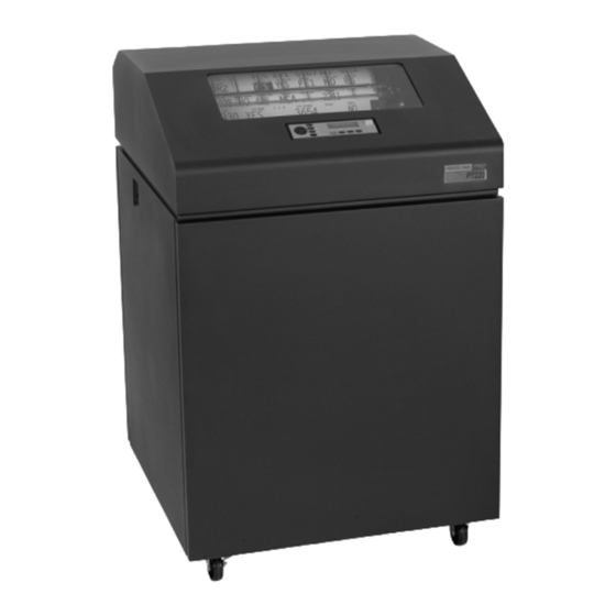
Printer Component Locations Printer Component Locations Familiarize yourself with the names and locations of the printer components, shown in Figure 1, before continuing with the rest of the installation procedures. Barcode Ribbon Ribbon Spool Date Code Label Splined Shaft Paper Support Hammer Bank Cover and Ribbon Mask... -
Page 9: Remove Packing Materials
Remove Packing Materials Remove Packing Materials CAUTION To avoid shipping damage, reinstall the shipping restraints whenever you move or ship the printer. Save the cardboard packing, foam blocks, and bubble wrap along with the other packing materials in case you need to move the printer. - Page 10 Remove Packing Materials Envelope Blue Tractor Door (2) Blue Tractor Lock (2) Platen Lever Figure 3. Removing the Sample Configuration Printout 2. Open the blue tractor doors. 3. Move the tractor locks to the middle position to unlock them. 4. Raise the platen lever to the fully open (raised) position. 5.
- Page 11 Remove Packing Materials Hammer Bank Protective Foam Figure 4. Removing the Hammer Bank Protective Foam 8. Remove the hammer bank protective foam between the ribbon mask and the platen.
- Page 12 Remove Packing Materials Platen Protective Foam Figure 5. Removing the Platen Protective Foam 9. Rotate the platen protective foam toward the front of the printer and out from under the support shaft. 10. Remove the platen protective foam.
- Page 13 Remove Packing Materials Wooden Block (6) Wooden Block Wooden Block Wooden Block Wooden Block Wooden Block Figure 6. Removing the Six Wooden Blocks 11. Remove the six wooden blocks.
-
Page 14: Adjust The Paper Supports
Adjust The Paper Supports Adjust The Paper Supports Paper Support Tab (2) Blue Paper Support (2) Blue Tractor Door (2) Figure 7. Adjusting Paper Supports Squeeze the paper support tabs and slide the blue paper supports inward until each one is approximately four inches from its corresponding blue tractor door. -
Page 15: Release The Paper Chains - Cabinet Model
Release The Paper Chains – Cabinet Model Release The Paper Chains – Cabinet Model NOTE: Steps 1– 3 in this section are for the passive stacker. If you have the power paper stacker installed, skip this procedure and go to “Remove The Shipping Restraints From The Power Paper Stacker (If Equipped)”... -
Page 16: Remove Tags - Cabinet Model
Remove Tags – Cabinet Model Remove Tags – Cabinet Model NOTE: If you have the power paper stacker installed, skip this procedure and go to “Remove The Shipping Restraints From The Power Paper Stacker (If Equipped)” on page 17. Passive Stacker Paper Fence (if equipped) Tie Wrap... -
Page 17: Remove The Shipping Restraints From The Power Paper Stacker (If Equipped)
Remove The Shipping Restraints From The Power Paper Stacker (If Equipped) Remove The Shipping Restraints From The Power Paper Stacker (If Equipped) This section applies only to printers with the power stacker installed. NOTE: The P7000HD does not support the power paper stacker. Special packaging protects the power stacker mechanisms from damage during shipment. - Page 18 Remove The Shipping Restraints From The Power Paper Stacker (If Equipped) Elevator Lift Handle Tie Wrap (5) Plastic Bag (3) Figure 10. Removing the Shipping Restraints 1. Open the rear door panel. 2. Remove the five tie wraps. 3. Raise the power paper stacker frame to its highest position by pulling up on the elevator lift handle.
-
Page 19: Remove The Paper Tent Tape
Remove The Paper Tent Tape Remove The Paper Tent Tape NOTE: If you have the passive paper stacker option, perform the following steps to set the paper tent, otherwise go to “Attach The Control Panel Overlay” on page 20. Tape Paper Tent Rear Tray Figure 11. -
Page 20: Attach The Control Panel Overlay
Attach The Control Panel Overlay Attach The Control Panel Overlay Overlay Label Figure 12. Attaching Control Panel Overlay 1. Choose the overlay label in the appropriate language. 2. Open the printer cover. 3. Peel the protective backing off the overlay and the blue tape from the window. -
Page 21: Connect The Interface And Power Cables
Connect The Interface And Power Cables Cabinet Model Connect The Interface And Power Cables Cabinet Model IMPORTANT To comply with Electromagnetic Compatibility (EMC) regulatory requirements all electrical signal interface cables connected to this printer must be of a minimal quality level, be of the correct length, and be properly installed. - Page 22 Connect The Interface And Power Cables I/O Connectors Power Switch I/O Cover Upper and Lower Standoffs AC Power Connection Cable-Routing Notches Figure 13. Routing the I/O Cable and AC Power Cable 1. Make sure the printer power switch is set to O (Off). 2.
- Page 23 Connect The Interface And Power Cables Cabinet Model I/O Cable Grommet Figure 14. Routing the I/O Cable 3. Hold the I/O cable below its connector and gently push the cable through the opening in the grommet seated in the notch. 4.
-
Page 24: Interface Connections (Cabinet And Pedestal)
Connect The Interface And Power Cables Interface Connections (Cabinet And Pedestal) NOTE: Your printer is equipped with either the V5 or V6 controller. Determine the type of controller you have by referring to Figure 15 and Figure 16. V5 Controller Ethernet option (if installed) or Coax/Twinax (if installed) Centronics Parallel... - Page 25 Interface Connections (Cabinet And Pedestal) V6 Controller Coax/Twinax (if installed) Centronics Parallel RS-422 (if installed) 9 Pin STD 9 Pin to 25 Pin STD Serial RS-232 Serial Adapter Diagnostic Ethernet 10/100 Base-T Coax/Twinax Figure 16. V6 Controller Board Interface Connections...
-
Page 26: Pedestal Model
Connect The Interface And Power Cables 1. Remove the cover from the I/O connector you have selected. 2. Attach the I/O cable connector to the printer interface connector. NOTE: P7000HD and P7000 H-Series printers do not support Coax/Twinax. Pedestal Model Power Switch AC Power Connector Figure 17. -
Page 27: Loading Ribbon And Paper
The following sections describe how to install ribbon and load paper. Loading Ribbon The P7000 requires ribbons that work with the Integrated Print Management System. Earlier P5000 and other legacy ribbons do not provide this support and will not work. - Page 28 Loading Ribbon And Paper Spool Right Hub Figure 19. Loading the Ribbon 4. Place the empty spool on the right hub. Be sure the ribbon feeds off the outside of the spool. 5. Press the spool down until it snaps into place. IMPORTANT The empty spool has a barcode label on the bottom side and a date code label on the top.
- Page 29 Loading Ribbon Ribbon Spool Left Hub Hammer Ribbon Loading Bank Cover Instructions (for future reference) Ribbon Mask Ribbon Guide (both sides) Figure 20. Threading the Ribbon Around the Ribbon Guide 6. Thread the ribbon around the ribbon guide and along the ribbon path.
-
Page 30: Loading Paper (Standard Configuration)
Loading Ribbon And Paper NOTE: If there are ink stained fingerprints on the ribbon barcode (located on the ribbon spool), wipe it clean with a soft cloth or towelette moistened with alcohol. Loading Paper (Standard Configuration) When you start this procedure, verify that the printer cover is open, the platen lever is raised, and the blue tractor doors are open. - Page 31 Loading Paper (Standard Configuration) Wire Guide (2) Paper Paper Slot Slot Metal Paper Guide (P7220 and P7280HD) Cabinet Model Pedestal Model Figure 22. Feeding the Paper Through the Paper Slot Pedestal Model a. Place the paper supply on the floor in front of the printer, or on the optional paper shelf, if attached.
- Page 32 Loading Ribbon And Paper Left Tractor Door Paper Left Tractor Lock Figure 23. Loading Paper onto the Left Tractor Sprockets 4. Load the paper on the left tractor sprockets. 5. Close the tractor door.
- Page 33 Loading Paper (Standard Configuration) CAUTION To avoid damage to the printer caused by printing on the platen, always position the left tractor unit directly to the left of the “1” mark on the paper scale. Tractor Splined Shaft Paper Tractor Paper Scale Figure 24.
- Page 34 Loading Ribbon And Paper Right Tractor Door Figure 25. Loading the Paper onto the Right Tractor Sprockets 7. Unlock the right tractor. 8. Load the paper onto the right tractor sprockets. 9. Close the tractor door. 10. Make sure the leading edge of the first sheet of paper is parallel to the top of the tractors.
- Page 35 Loading Paper (Standard Configuration) Vertical Position Knob Paper Thickness Indicator Platen Stop Platen Lever Platen Stop Knob Figure 26. Set the Platen Lever based on the Paper Thickness 13. Raise the platen lever all the way. 14. Turn the vertical position knob to feed the paper up into the paper guide assembly.
- Page 36 Loading Ribbon And Paper 18. Press the PAPER ADVANCE key several times to make sure the paper feeds properly beyond the tractors over the lower paper guide. Feed sufficient paper to ensure the paper stacks correctly. 19. Close the printer cover. 20.
-
Page 37: Set The Top-Of-Form
Set The Top-Of-Form Loading Paper (Standard Configuration) Set The Top-Of-Form Every time you load paper, you set the top-of-form (TOF) location. This procedure must be performed the first time paper is introduced into the printer, and every time new paper is loaded. 1. - Page 38 Set The Top-Of-Form TOF Indicator Perforation Vertical Position Knob Figure 28. Aligning the First Print Line with the TOF Indicator 3. Locate the TOF indicator. It is a small tab located on both the right and left tractor doors. 4. Turn the vertical position knob to align the top of the first print line with the TOF indicator.
- Page 39 Set The Top-Of-Form Loading Paper (Standard Configuration) Platen Lever Figure 29. Closing the Platen Lever 5. Lower the platen lever until it stops. 6. Press ON LINE/CLEAR to remove any fault messages (such as “LOAD PAPER”) from the message display. 7.
-
Page 40: Adjust The Paper Fence - Cabinet Model
Adjust The Paper Fence – Cabinet Model Adjust The Paper Fence – Cabinet Model Left Adjustment Hole (5) Bottom Adjustment Hole (5) Paper Fence Bracket Paper Fence Upper Bar Finned End (of Paper Center Post Fence Upper Bar) Figure 30. Adjusting the Paper Fence 1. -
Page 41: Adjust The Optional Passive Paper Stacker - Cabinet Model
Adjust The Optional Passive Paper Stacker – Cabinet Model Loading Paper (Standard Configuration) 3. Insert the finned end of the paper fence upper bar into the corresponding bracket inset, snapping it into place. 4. Close the cabinet door. Adjust The Optional Passive Paper Stacker – Cabinet Model Passive Stacker Handle... -
Page 42: Power Paper Stacker Option
Power Paper Stacker Option 1. Pull the passive stacker handle up. 2. Move the passive stacker forward or back for proper paper adjustment. 3. Release the passive stacker handle. 4. Close the cabinet door. Power Paper Stacker Option This section explains how to set up and use the optional power paper stacker. -
Page 43: Power Paper Stacker Component Locations
Power Paper Stacker Component Locations Power Paper Stacker Component Locations Familiarize yourself with the names and locations of the components, shown in Figure 32, before operating the paper stacker. Paper Throat Rear Control Panel Elevator Disable Switch Pinch Rollers Elevator Lift Handle Paper Length Indicator... -
Page 44: Setting Up The Power Paper Stacker
Power Paper Stacker Option Setting Up The Power Paper Stacker Elevator Disable Switch Elevator Lift Handle Paper Advance Stacker Up Stacker Down Figure 33. Use the Rear Control Panel to Set Up the Power Stacker 1. Using the rear control panel, press ON LINE/CLEAR to take the printer offline. - Page 45 Setting Up The Power Paper Stacker Paper Stacker Rails Wire Paper Tent Figure 34. Power Stacker Components 3. Make sure the wire paper tent is fitted in the pull out paper tray in the base of the stacker.
- Page 46 Power Paper Stacker Option Paper Length Indicator Paddle Shaft Bearing Bracket Figure 35. Setting the Paper Length 4. Set the desired paper length (5 to 12 inch range), as follows: Grasping the paddle shaft, push or pull towards the front or the rear of the printer, setting the desired paper length by aligning the indicator notch on the bearing bracket with the paper length indicator.
-
Page 47: Loading And Starting The Power Paper Stacker
Loading And Starting The Power Paper Stacker Loading And Starting The Power Paper Stacker Wire Paper Tent Figure 36. Stacking Sheets of Paper on the Wire Paper Tent 1. Using the rear control panel, press the PAPER ADVANCE key and hand feed the paper in the paper throat. Continue to advance the paper until it reaches the wire tent and there is an excess of 3 to 5 pages in the stacker. - Page 48 Power Paper Stacker Option Rear Control Panel Paper Guide Figure 37. Returning the Stacker Frame to its Proper Position 3. Press the ON LINE/CLEAR key, from either the front or rear control panel, to put the printer in the online state. The stacker frame then returns to its proper position for printing.
-
Page 49: Front Access Paper Stacker Option
Front Access Paper Stacker Option Loading And Starting The Power Paper Stacker Front Access Paper Stacker Option Paper Holding Shelf Sliding Tray NOTE: D = Maximum Height of Finished Forms Figure 38. Optional Front Access Paper Stacker 1. Measure the distance “D” from the bottom margin of the paper holding shelf to the sliding tray surface. -
Page 50: Checking The Paper Feed - Cabinet Model
Checking The Paper Feed – Cabinet Model Checking The Paper Feed – Cabinet Model Paper Guide Figure 39. Side View of the Cabinet Model Showing Paper Feed Route 1. Check that the paper feeds correctly. 2. Press the Form Feed key several times to ensure that the paper feeds properly beyond the tractors and over the paper guide assembly. -
Page 51: Attach The Input Paper Shelf And Output Basket - Pedestal Model
Attach The Input Paper Shelf And Output Basket – Pedestal Model Loading And Starting The Power Paper Stacker Attach The Input Paper Shelf And Output Basket – Pedestal Model Ground Wire Screw Upper Output Basket (Optional) Wire Form Input Paper Back Stop Shelf (Optional) Output... - Page 52 Attach The Input Paper Shelf And Output Basket – Pedestal Model 1. Squeeze the paper support tabs and slide the two blue paper supports toward the center of the support shaft. Position them so that they divide the space between the tractors into three approximately equal segments.
-
Page 53: Install The Optional Acoustic Shroud - Pedestal Model
Install The Optional Acoustic Shroud – Pedestal Model Loading And Starting The Power Paper Stacker Install The Optional Acoustic Shroud – Pedestal Model Acoustic Shroud Latch (2) Molded Bracket (2) Figure 41. Attaching the Acoustic Shroud 1. Holding the latches open (rotated to the rear), install the acoustic shroud hinges on the brackets molded into the back of the top cover. -
Page 54: Quick Access Cover Setup - Pedestal Model
Quick Access Cover Setup – Pedestal Model Quick Access Cover Setup – Pedestal Model The quick access cover on the pedestal model allows the paper to exit through the top of the printer. Quick Access Cover Paper Paper Tear Bar Figure 43. -
Page 55: Top Paper Exit
Quick Access Cover Setup – Pedestal Model Loading And Starting The Power Paper Stacker Top Paper Exit Top Cover Paper Exit Slot Blue Captive Screw (2) Quick Access Paper Deflector Quick Access Blue Deflector Cover Thumbwheel Figure 44. The Quick Access Cover on the Pedestal Model 1. -
Page 56: Checking The Paper Feed - Pedestal Model
Checking The Paper Feed – Pedestal Model Checking The Paper Feed – Pedestal Model Rear Exit Top Exit Figure 45. Side View of the Pedestal Model Showing Paper Feed Routes NOTE: When using the top exit paper path, paper cannot be stacked. -
Page 57: Ribbon Life Indicator
The Control Panel Loading And Starting The Power Paper Stacker The Control Panel Message Display PRT CONFIG Emulation Status Indicator Circular SET TOF ONLINE <PGL> RIBBON LIFE 100% JOB SELECT VIEW/EJECT ON LINE/CLEAR CANCEL Ribbon Life PAPER ADVANCE ENTER Indicator Figure 46. -
Page 58: Printer Self-Test
Printer Self-Test When printing stops at 0%, and if immediately changing the ribbon is not convenient, you can place the printer back online and printing will resume for a short period. Printer Self-Test Each time you power on the printer, it executes a self-test. The default power-up state is online. -
Page 59: P7000 Quick Setup Menu
P7000 Quick Setup Menu P7000 Quick Setup Menu QUICK SETUP Host Device ID Adapter Ethernet WLAN Interface Address Address Address Auto Switching* IPDS* IP Address IP Address IP Address Centronics 5225 Subnet Mask Subnet Mask Subnet Mask Dataproducts 4234-2 Gateway Address... - Page 60 Quick Setup Menu QUICK SETUP (continued) Select CPI Select LPI P-Series Margins Form SFCC Length 10.0 CPI* 6.0 LPI* Left Margin Funct. of Lines 12.0 CPI 8.0 LPI 00-7F Right Margin 66 Lines* 13.3 CPI 10.3 LPI Top Margin (1-192) 15.0 CPI Bottom Margin 17.1 CPI...
-
Page 61: P7000Hd Quick Setup Menu
P7000HD Quick Setup Menu P7000HD Quick Setup Menu * = Factory Default QUICK If installed. SETUP Host Adapter Ethernet Forms Ribbon End Interface Address Address Length Point Auto Switching* IP Address IP Address Abs. Length IN Darker +6 Centronics Subnet Mask Subnet Mask 11.0* inches Darker +5... -
Page 62: P7000 H-Series Quick Setup Menu
Quick Setup Menu P7000 H-Series Quick Setup Menu * = Factory Default Available for Hanzi and Kanji LP+ Printers Only QUICK Available for Hangul LP+ Printers Only SETUP If installed Available for Zero Tear Pedestal Printers Only Host Adapter Ethernet... -
Page 63: Host Interface
P7000 H-Series Quick Setup Menu * = Factory Default QUICK SETUP Available for Hanzi and Kanji LP+ Printers Only (continued) Available for Hangul LP+ Printers Only If installed Available for Zero Tear Pedestal Printers Only Load Save Power-Up Config. Config. - Page 64 Active IGP Emulation The Active Emulation menu enables you to activate either the PGL or VGL emulation. NOTE: This option applies to the P7000 only, not the P7000HD. Ribbon End Point This parameter adjusts the point at which the system will declare the ribbon as being expended.
-
Page 65: Print A Test Page
Print A Test Page P7000 H-Series Quick Setup Menu Print A Test Page Now you will print the printer’s current configuration by following the instructions below: Step Press Result Notes Make sure the printer is on. ON LINE/CLEAR OFFLINE QUICK SETUP... - Page 66 Print A Test Page Step Press Result Notes Press until the desired Print Config. option displays. UNTIL The configuration listing ENTER OFFLINE begins to print, then the QUICK SETUP printer goes back offline. Carefully tear off the configuration printout. Locks the ENTER key. ENTER SWITCH LOCKED ON LINE/CLEAR...
-
Page 67: Contact Information
Europe, Middle East, and Africa (31) 24 6489 410 Asia Pacific (65) 6548 4114 http://www.printronix.com/public/servicessupport/default.aspx Printronix Supplies Department Contact the Printronix Supplies Department for genuine Printronix supplies. Americas (800) 733-1900 Europe, Middle East, and Africa (33) 1 46 25 1900... -
Page 68: Corporate Offices
Singapore 486763 Phone: (65) 6542 0110 Fax: (65) 6546 1588 Visit the Printronix web site at www.printronix.com For More Information This Quick Setup Guide provides general information for use of your printer. Refer to the User’s Manual (located on the CD-ROM included with this book) for more detailed information including: •... - Page 69 Printronix representative for information on the products and services currently available in your area. Any reference to a Printronix product, program, or service is not intended to state or imply that only that Printronix product, program, or service may be used.
- Page 70 Web sites. The materials at those Web sites are not part of the materials for this Printronix product and use of those Web sites is at your own risk.
- Page 71 • Transfer the original unaltered copy of the documentation when you transfer the related Printronix product (which may be either machines you own, or programs, if the program’s license terms permit a transfer). You must, at the same time, destroy all other copies of the documentation.
-
Page 72: Energy Star
Printronix participates in this program by introducing printers that reduce power consumption when they are not being used. As an Partner, Printronix has determined that this product... - Page 73 UL is a registered certification mark of Underwriters Laboratories, Inc. ENERGY STAR is a registered trademark of the United States ® Environmental Protection Agency. As an ENERGY STAR Partner, Printronix has determined that this product meets the ENERGY STAR guidelines for energy efficiency.
-
Page 74: Product Recycling And Disposal
Batteries of these types must be recycled or disposed of properly. Recycling facilities may not be available in your area. In the United States, Printronix has established a collection process for reuse, recycling, or proper disposal of used batteries and battery packs from Printronix equipment. - Page 75 Properly shielded and grounded cables and connectors must be used in order to meet FCC emission limits. Printronix is not responsible for any radio or television interference caused by using other than recommended cables and connectors or by unauthorized changes or modifications to this equipment.
- Page 76 Properly shielded and grounded cables and connectors must be used in order to reduce the potential for causing interference to radio and TV communications and to other electrical or electronic equipment. Printronix cannot accept responsibility for any interference caused by using other than recommended cables and connectors.
-
Page 77: German Conformity Statement
EN 55024 festgelegt), dann kann es dabei eventuell gestört werden. In solch einem Fall ist der Abstand bzw. die Abschirmung zu der industriellen Störquelle zu öergrvßern. Anmerkung: Um die Einhaltung des EMVG sicherzustellen sind die Geräte, wie in den Printronix Handbüchern angegeben, zu installieren und zu betreiben. - Page 78 Communication Statements China Declaration: This is a Class A product. In a domestic environment this product may cause radio interference in which case the user may need to perform practical actions.
- Page 79 Taiwan Warning: This is a Class A product. In a domestic environment this product may cause radio interference in which case the user will be required to take adequate measures.
-
Page 80: Lithium Battery Warning
Lithium Battery Warning Korea CAUTION: This product is equipped with a 3-wire power cord and plug for the user’s safety. Use this power cord in conjunction with a properly grounded electrical outlet to avoid electrical shock. Lithium Battery Warning The controller board contains a lithium battery sealed inside the real-time clock chip. -
Page 81: Software License Agreement
Agreement by your initial use of your printer. 1. Object Code License Printronix grants you a nonexclusive license to use the Printronix Software, the eCos Software and all other embedded software (collectively, the “Embedded Software” or the “Software”) only in conjunction with the printer. - Page 82 You agree that this Agreement provides you no more rights with regards to warranty, support, indemnity or liability terms with respect to Red Hat, Inc., Printronix, Inc. or any contributor to the Embedded Software than that provided by the Red Hat eCos Public License v.1.1 or any express warranty that may be made by...
- Page 83 5. Limitation of Liability UNDER NO CIRCUMSTANCES AND UNDER NO LEGAL THEORY, WHETHER TORT (INCLUDING NEGLIGENCE), CONTRACT, OR OTHERWISE, SHALL RED HAT, PRINTRONIX, ANY OTHER CONTRIBUTOR, OR ANY DISTRIBUTOR OF THE EMBEDDED SOFTWARE, OR ANY PART THEREOF, OR ANY SUPPLIER OF ANY OF SUCH PARTIES, BE LIABLE TO YOU OR...
- Page 84 Software License Agreement 7. Miscellaneous This Agreement represents the complete agreement concerning subject matter hereof. If any provision of this Agreement is held to be unenforceable, such provision shall be reformed only to the extent necessary to make it enforceable. This Agreement shall be governed by California law provisions (except to the extent applicable law, if any, provides otherwise), excluding its conflict-of- law provisions.
- Page 85 Component Locations Load Ribbon, 27 Power Paper Stacker, 43 printer, 8 Menu Contact information, 67 P7000 H-Series Quick Setup, 62 Control Panel, 57 P7000 Quick Setup, 59 Control Panel Overlay, 20 P7000HD Quick Setup, 61 Customer Support Center, 67 Quick Setup, 58...
- Page 86 Host Interface, 63 Paper Supports, adjust, 14 Load Config., 64 Paper Tent, remove, 19 P7000, 59 Paper, loading, 30 P7000 H-Series, 62 Passive Paper Stacker, adjust, 41 P7000HD, 61 Pedestal Model Power-Up Config, 64 attach input paper shelf, 51 Ribbon End Point, 64...
- Page 87 Index Save Config, 64 Self-Test, printer, 58 Setting Top-of-Form, 37 Setup, Power Paper Stacker, 44 Shipping Restraints, Power Paper Stacker, 17 Supplies Department, 67 Tags, remove, 16 Test Page, print, 65 TOF, setting, 37 Top-of-Form, setting, 37...
- Page 88 Index...
- Page 90 *178661-001* 178661-001D...
Need help?
Do you have a question about the P7000 and is the answer not in the manual?
Questions and answers