Sign In
Upload
Manuals
Brands
Printronix Manuals
Printer
P600
Printronix P600 Manuals
Manuals and User Guides for Printronix P600. We have
3
Printronix P600 manuals available for free PDF download: Maintenance Manual, User's Reference Manual
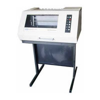
Printronix P600 Maintenance Manual (324 pages)
Line printer
Brand:
Printronix
| Category:
Printer
| Size: 4 MB
Table of Contents
Maintenance Manual
1
About this Manual
5
Table of Contents
7
Chapter 1. Maintenance Overview
15
Introduction
15
Printer Description
15
Specifications
16
Operation
16
Printer: Pedestal Model and XQ Cabinet Model
17
External Controls and Indicators
18
External Controls and Indicators
19
Internal Controls and Indicators
20
Internal Controls and Indicators
21
Controls and Indicators for Options on Pedestal Models
22
Chapter 2. Principles of Operation
23
Scope
23
Basic Functions and Circuit Locations
23
Principle States of Operation
23
Buffer Load State
23
Printer System Block Diagram
24
Power Supply Assembly
24
Location of Functional Elements on Pcbas
25
Buffer Load State Block Diagram
28
Interface Block Diagram
29
Interface Timing
30
Interface Signals
31
Print State
32
Dot Selection Block Diagram
33
Defining the Dot Matrix
35
Typical Characters (Data Processing Mode)
35
Dot Column and Character Column Timing for One Shuttle Cycle
38
Dot Column and Character Column Counter Block Diagram
39
Plotting the Six Bit Code
41
Hammer Driver Block Diagram
44
Hammer Driver Circuit Timing
45
Safety Circuits
46
Hammer Reset Timer
47
Dot Row Timing Vs Timing Disk and Cam Position
49
Operation of MPU Circuit
50
Hammer and Shuttle Arrangement
51
Print Hammer Action
52
Standard Character Formation
53
P600 Phase Fire Operation
55
Hammer Bank Shuttle Components
56
Paper Feed State
57
Paper Feed Logic Block Diagram
59
Line Feed Operation Velocity Profile
61
Timing Sequence for Printing One Character Line
62
Top-Of-Form Counter Block Diagram
64
Top-Of-Form Slewing Velocity Profile
65
Paper Feed to Top-Of-Form Timing
66
EVFU Loading Block Diagram
68
EVFU Loading Sequence Timing Diagram
68
EVFU Channel Seek Block Diagram
70
EVFU Channel Seek Velocity Profile
71
EVFU in Binary Count Mode
72
Paper Transport Components
74
Paper Motion Detector Diagram
76
Paper Feed Control Circuits Block Diagram
77
Ribbon Transport
78
Ribbon Drive Block Diagram
78
Ribbon Control PCBA Simplified Schematic
79
Power Supply
83
V and +70 V Supplies
85
Reference Voltage Circuit
86
V and MOS Supplies
87
Relay Switching Details
89
Motor Relay Trigger Circuit
90
Chapter 3. Preventive Maintenance
91
General
91
Preventive Maintenance Checks and Service
91
Inspection
91
Cleaning
92
Physical Inspection
92
Cleaning Interior of Cabinet
93
Cleaning Hammer Bank Assembly–Ribbon Drive to Service Position
97
Cleaning Hammer Bank Assembly–Hammer Bank to Service Position
98
Lubrication
100
Lubrication, Counterweight and Cam Wick
101
Lubrication, Self–Aligning Cam Followers, P600 Only
103
Lubrication, Antirotation Arm, P300 Only
105
Chapter 4. Troubleshooting
107
General
107
Common Causes of Malfunctions
107
Testing
107
Fault Isolation
107
Performance Tests
107
POWER Indicator Not Illuminated
108
ON LINE Indicator Not Illuminated
108
Not Printing
108
Light And/Or Smeared Characters
108
Horizontal Misalignment
108
Vertical Misalignment
108
Malfunction Symptom Index
108
Confidence Check
109
New Printer Does Not Operate
113
CHECK Indicator Stays on
116
Shuttle Does Not Accelerate to Speed When on LINE Switch Is Pressed
120
Ribbon Does Not Advance
121
Ribbon Folds over
123
Ribbon Not Feeding Smoothly
124
End of Ribbon Not Detected
126
Missing Characters
130
Missing Characters, Example of
134
Missing Dots
135
Missing Dots
141
Light And/Or Smeared Characters, Example of
144
Misplaced Dots
145
Print too Light or Dark
149
Print too Light or Dark
151
Vertical Misalignment Character Position, Example of
158
Vertically Deformed Characters, Example of
159
Vertical Compression of Print
160
Garbled Letters And/Or Wrong Font
161
No Paper Feed
163
Paper Feeds Erratically
167
Paper Drags
172
Top-Of-Form Does Not Operate
175
Shift Recycle Test - Sliding Pattern
177
Plot Pattern Test
178
MPU Phasing Test - All Hs
179
Row Increment Test - Uppercase Characters
180
Underline/Vertical Hammer Alignment Test
181
Chapter 5 . Corrective Maintenance
183
Section I. GENERAL
183
Introduction
183
Tools, Test Equipment, and Supplies
183
Tools, Test Equipment, and Supplies
184
Section II. ALIGNMENTS and ADJUSTMENTS
185
Ribbon Hub Height Adjustment
185
Ribbon Hub Height Adjustment
186
Ribbon Tracking Check and Adjustment
187
Shuttle Spring Force Adjustment
190
Hammer Spring Retensioning
194
Hammer Tip Alignment
196
Setting Shuttle and Counterweight Preload
194
Hammer Tip Alignment
197
Hammer Tip Height (Protrusion) Adjustment
198
Hammer Tip Height Adjustment
199
Platen Gap
200
Magnetic Pickup Gap
202
Magnetic Pickup Phasing Adjustment
204
Adapting Shuttle Motor to Line Frequency
205
Shuttle Belt
206
Paper Feed Belt
208
Paper Feed Belt Tension Check and Adjustment
209
Paper Motion Sensor
210
Paper out Detectors
212
Section III. REPLACEMENT
214
Printer Cover
214
Cover Removal/Installation, Pedestal Models
216
Cover Removal/Installation, Floor Cabinet (XQ) Models
217
Control Panel
218
Control Panel Removal/Installation
219
Ribbon Drive
220
Ribbon Drive Removal/Installation, Pedestal Models
222
Ribbon Drive Removal/Installation, Floor Cabinet (XQ) Models
223
Ribbon Control PCBA
224
Ribbon Control PCBA Removal/Installation, Pedestal Models
225
Ribbon Drive Motor
226
Ribbon Drive Motor Removal/Installation
227
Ribbon Drive Blower
228
Ribbon Drive Blower Removal/Installation, Pedestal Models
230
Shuttle Assembly
232
Hammer Spring
238
Hammer Spring Removal/Installation
239
Hammer Coil
241
Counterweight Assembly
244
Flywheel Assembly
247
Flywheel Assembly Removal/Installation
248
Cam Wick
249
Magnetic Pickup
249
Cam Wick Removal/Installation
250
Magnetic Pickup Removal/Installation
251
Shuttle Motor Removal/Installation
253
Shuttle Belt
254
Shuttle Motor
254
Shuttle Belt Removal/Installation
255
Paper Ironer
256
Paper Ironer Removal/Installation
257
Paper Feed Belt
258
Paper Feed Motor
260
Paper Feed Motor Removal/Installation
261
Tractor Removal/Installation
263
Tractor
264
Paper Motion Sensor Removal/Installation
265
Paper Motion Sensor
266
Paper out Mechanical Switch Removal/Installation
267
Paper out Optical Sensor
268
Paper out Optical Sensor Removal/Installation
269
DC Power Supply Fuse
270
DC Power Supply Fuses Removal/Installation
271
Power Supply PCBA
272
Power Supply PCBA Removal/Installation
273
Power Supply
274
Power Supply Removal/Installation
275
Rear Fan
276
Rear Fan Removal/Installation, Pedestal Models
277
Rear Fan Removal/Installation, Floor Cabinet (XQ) Models
278
Logic PCBA
280
Logic PCBA Removal/Installation
281
Hammer Driver PCBA
282
Hammer Driver PCBA Removal/Installation
283
Hammer Bank Cable Harness Removal/Installation
285
Hammer Bank Cable Harness
287
Parts List
293
Ribbon Tracking Check and Adjustment
294
Setting Shuttle and Counterweight Preload
295
Shuttle Spring Force Adjustment
295
Hammer Spring Retensioning
296
Magnetic Pickup Gap and Phasing Adjustment
296
Platen Gap Adjustment
296
Paper Motion Sensor Check and Adjustment
297
Paper out Detector Adjustment
297
Shuttle Belt Tension Check and Adjustment
297
Shuttle Assembly Removal/Installation
301
Screw
301
Washer
301
Card Cage
301
Hammer Coil Removal/Installation
302
Washer (2)
302
Counterweight Assembly Removal/Installation
303
Screw (4)
304
Nut (4)
305
Paper Feed Belt Removal/Installation
306
Power Supply Assembly
309
Power Supply Pcba
309
Advertisement
Printronix P600 User's Reference Manual (153 pages)
P-Series
Brand:
Printronix
| Category:
Printer
| Size: 5 MB
Table of Contents
Table of Contents
3
List of Figures
6
List of Tables
8
Introduction
10
P Series General Description
11
Dot Character Formation
13
Dot Matrix Line Printing
13
Printponix Character Formation
13
Operation
14
Operator Panel Controls and Indicators
16
Operator Panel and Power Switch
16
Operator Panel Switches and Indicators
17
Paper Adjustment Controls
18
Forms Thickness Adjustment Lever
18
Paper Tractors and Horizontal Adjustment Knob
19
Vertical Position Knob, Disk and Forms Length Selector
20
Top-Of-Form Adjustment
21
Top of Form Reference Mark
21
Setting the Top of Form
22
Optional Controls
23
Forms Length Selector Option
23
Compressed Print Option
24
Compressed Print Switch
24
Multi-Mode Print Option
25
Multi-Mode Print Switch
25
Host Computer Control Codes
26
ASCII Control Characters
26
Loading/Unloading Paper
27
Changing Ribbon
27
P-Series Ribbon Deck
27
Cleaning
28
Cleaning Paper Motion Detector and Ribbon Path
28
Vacuum Cleaning
29
Configuration
30
Host Controlled Functions
32
Hardware Selectable Functions
34
Logic Printed Circuit Boards
36
Card Cage Location
36
Logic Board Identification
37
PCBA Removal and Replacement
44
Tools Required
44
Hardware Configuration
45
Alternate Form Length
46
Alternate Forms Length Jumper
46
Character Height
47
Character Height Jumpers
47
Character Underline
48
Character Underline Jumper
48
Control Code Select
49
Electronic Vertical Format Unit
50
EVFU Jumper
50
High Vertical Resolution Character PROM Socket
51
High Vertical Resolution Character PROM Socket Jumpers
51
Interface Parameters
52
Interface Parameters Jumpers
52
Line Spacing
53
Line Spacing Jumpers
53
Line Feed Control
54
Modified Plot
55
Modified Plot Jumper
55
Binary Count Jumper
55
Multi-Mode Print
56
Multi-Mode Print Jumpers
56
Paper Fault Operation
57
Paper Fault Operation Jumpers
57
Paper Motion Detector
57
Phase Fire Enable
58
Plot Mode Parameters
58
Phase Fire Enable Jumper
58
Print Lowercase as Uppercase
59
Printer Model Select
60
Printer Model Select Jumpers
60
Skip over Perforation Length
61
Optional/Custom Character Proms
62
Summary of Hardware Selectable Functions
63
Logic a and B Pcbas
70
Programming
75
Character Print Mode
76
Plot Mode
76
P Series Printer Control Codes
77
Standard ASCII Character Set and Control Codes
78
Draft Print
80
Compressed Print
81
Elongated Characters
82
Carriage Return
83
Line Feed
83
Vertical Tab
83
8 Lines Per Inch Spacing
84
Underline
84
Space
85
Delete
85
Alternate Character Set Option
86
Dot Format and Resolution
87
Normal Resolution
87
High Resolution
87
Plot Speed
88
Programming in Plot Mode
88
Plot Data Line Format
88
Plot Data Byte Format
89
Data Byte Dot Patterns
90
Odd Dot Plot
91
Event Dot Plot
92
Combining Graphics and Characters
93
Plot Mode Text
93
Print Mode/Plot Mode
93
EVFU Operating Program
94
General EVFU Programming Information
94
Default Operation
95
Runaway Protection
95
EVFU Control and Channel Codes
96
Start Load
96
End Load
96
Form Feed
96
Form Line Spacing
98
Typical Form Line Spacing
98
EVFU Form Definition Program
99
EVFU Form Definition Load Program
101
Slew Relative Programming
103
EVFU Slew Relative Codes
103
Corrective Maintenance
105
Test Pattern Printing
107
Corrective Maintenance Flowchart
107
Printer Interface
110
Interface Characteristics
111
Interface Terminating Resistors
112
Interface Line Driver and Receiver Circuit
112
Interface Cable Requirements
113
Interface Cable Lengths
113
Centronics Compatible Interface
114
Cetronics Interface Connector Pin Identification
114
Input Signals
115
Output Signals
116
Dataproducts Compatible Interface
117
Dataproducts Pin Identification
117
Installation
120
Site Preparation
122
AC Line Power Requirements
122
Unpacking and Inspection
123
Pedestal Assembly
124
Pedestal Mounting
125
Removing Rubber Feet
125
Ground Connection
126
Table Top Mounting
127
Table Preparation
127
Shipping Restraints
128
Removing Shipping Restraints
128
Ribbon and Paper
129
Cable Connection
129
Printer Cables and Labels
129
Preliminary Test
130
P-Series Printer Specifications
132
Accessories
137
Options
138
Intelligent Graphics Processor
138
Configuration Checklist
142
Logic A1 & B4 Pcbas
147
EVFU Control Codes
152
Printronix P600 User's Reference Manual (148 pages)
Brand:
Printronix
| Category:
Printer
| Size: 6 MB
Table of Contents
Fcc Compliance Statement
3
Table of Contents
6
Dot Matrix Line Printing
9
Operation
10
Paper Adjustment Controls
14
Top-Of-Form Adjustment
17
Printer Function
22
Phase Fil
31
Tools Required
40
Hardware Configuration
41
Character Height
43
Line Spacing
49
Print Lowercase as Uppercase
55
Printer Madel Select
56
Optional/Custom Character Proms
58
Summar~ of Hardware Selectable Functions
59
Skip over Perforation
65
Logic a and Pcbas
66
Programming
71
Character Print Mode
72
Data Processing Print
75
Draft P
76
Compressed Print
77
Carriage Return COD Hex
79
Line Feed <OA Hex
79
Vertical Tab <OB Hex
79
Form Feed <OC Hex
79
Lines Per Inch Spacing C06 Hex)
80
Unde
80
Space <20 Hex
80
Alternate Character Set Option
82
Plot Mode
83
Plot Speed
84
Prog
85
Odd Dot Plot <OS Hex
87
Even Dot Plot <04 Hex
88
Electronic Vertical Format Unit <EVFU
90
EVFU Operating Program
90
Evfu Control and Channel Codes
92
Slew Relative Programming
99
Corrective Maintenance
102
Printer Interface
106
Logic Levels
107
Maximum Cable Length
109
Installation
116
Site Preparation
118
Unpacking and Inspection
119
Pedestal Assembly
120
Tools Required
120
Pedestal Mounting
122
Specifications & Accessories
123
Cable Connection
126
Preliminary Test
127
Specification
128
Plot Mode
128
External Indicators
131
Draft Print
135
Compressed Print
135
Configuration Checklist
138
Jumper Function
138
Plot Data Line Format
141
Plot Data Bvte Format
141
Plot Data Byte Format
142
Advertisement
Advertisement
Related Products
Printronix P6000 series
Printronix P6000L
Printronix P6200L
Printronix P6040
Printronix P6080
Printronix P5220
Printronix P7220
Printronix P7080HD
Printronix P8000HDZT
Printronix P5005B-12
Printronix Categories
Printer
Label Maker
All in One Printer
Printer Accessories
Barcode Reader
More Printronix Manuals
Login
Sign In
OR
Sign in with Facebook
Sign in with Google
Upload manual
Upload from disk
Upload from URL