Barco ImagePRO-II User Manual
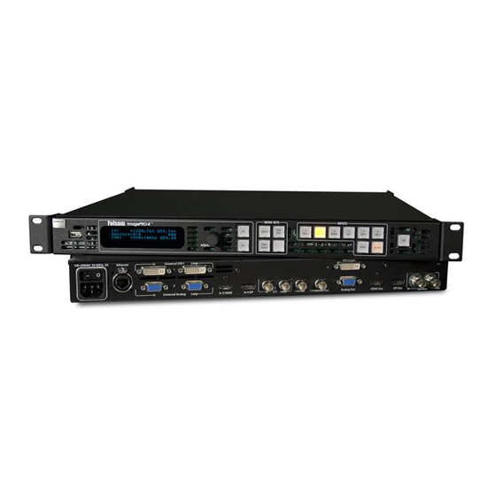
High-performance all-in-one video scaler, scan converter, switcher and transcoder
Hide thumbs
Also See for ImagePRO-II:
- Specifications (8 pages) ,
- Quick start manual (3 pages) ,
- User manual addendum (19 pages)
Table of Contents
Advertisement
Advertisement
Table of Contents

Subscribe to Our Youtube Channel
Related Manuals for Barco ImagePRO-II


Summary of Contents for Barco ImagePRO-II
- Page 1 fã~ÖÉmolJff » rëÉêÛë=dìáÇÉ • PN 26-0904000-00 • Revision 00...
- Page 2 30 days after the transfer of risks. In the event of justified notice of compliant, Barco can repair the fault or provide a replacement at its own discretion within an appropriate period. If this measure proves to be impossible or unsuccessful, the purchaser can demand a reduction in the purchase price or cancellation of the contract.
- Page 3 Not included in the guarantee coverage are system failures which are attributed to programs or special electronic circuitry provided by the purchaser, e.g. interfaces. Normal wear as well as normal maintenance are not subject to the guarantee provided by Barco either.
- Page 4 To avoid fire hazard, use only the fuse having identical type, voltage rating, and current rating characteristics. Refer fuse replacement to qualified service personnel. aç=kçí=léÉê~íÉ=áå=bñéäçëáîÉ=^íãçëéÜÉêÉë To avoid explosion, do not operate this product in an explosive atmosphere. ImagePRO-II • User’s Guide...
- Page 5 For more information about recycling of this product, please contact your local city office or your municipal waste disposal service. For details, please visit the Barco website at: http://www.barco.com/en/AboutBarco/weee qìêâÉó=oçep=`çãéäá~åÅÉ==...
- Page 6 Information Products” (Also called RoHS of Chinese Mainland), the table below lists the names and contents of toxic and/or hazardous substances that Barco’s product may contain. The RoHS of Chinese Mainland is included in the MCV standard of the Ministry of Information Industry of China, in the section “Limit Requirements of toxic substances in...
- Page 7 “Electronic Information Products Pollution Control Labeling Standard” of Chinese Mainland, marked with the Environmental Friendly Use Period (EFUP) logo. The number inside the EFUP logo that Barco uses (please refer to the photo) is based on the “Standard of Electronic Information Products Environmental Friendly Use Period”...
- Page 8 `Ü~åÖÉ=eáëíçêó The following table lists the changes to the ImagePRO-II User’s Guide. Change History Table 0-1. Date ECO # Description Approved By December 2011 592648 Initial release R. Pellicano viii ImagePRO-II • User’s Guide...
-
Page 9: Table Of Contents
ImagePRO-II Features........4... - Page 10 ImagePRO-II Menu Tree ........
- Page 11 Creating Pan and Zoom Settings with the Web App Interface ... 126 Viewing and Resetting Recent Changes ......127 ImagePRO-II • User’s Guide...
- Page 12 Introduction..........148 ImagePRO-II Remote Commands ....... . 149 Input Remote Commands .
- Page 13 Contact Information ......... . . 174 ImagePRO-II • User’s Guide...
- Page 14 Table of Contents ImagePRO-II • User’s Guide...
-
Page 15: Chapter Structure
NK==fåíêçÇìÅíáçå This chapter is designed to introduce you to the ImagePRO-II and to the content of and conventions used in this guide. The following topics are included in this chapter: • Chapter Structure • How to Use This Guide •... - Page 16 Web Interface, the “>” symbol is used to divide successive menu selections. Example: To access the Set Static IP Menu, select System > Ethernet > Set Static IP. ImagePRO-II • User’s Guide...
- Page 17 600, 1024 x 768, 1280 x 1024, etc. • Logo — A full-screen still image that you can capture, import, and store for subsequent display by the ImagePRO-II. • High-Bandwidth Digital Content Protection (HDCP) — A standard for encryption, defined by Intel Corporation to prevent copying of encrypted digital audio and video content.
-
Page 18: Imagepro-Ii Universal Video Processor
Control Overview fã~ÖÉmolJff=råáîÉêë~ä=sáÇÉç=mêçÅÉëëçê The ImagePRO-II is a high-performance all-in-one video scaler, scan converter, switcher and transcoder. The ImagePRO-II converts a wide range of user-selectable video input ™ signals — including RGB, HDTV, DisplayPort, HDMI , component, S-video, composite (NTSC, PAL) and HD/SDI — into an impressive array of output signal formats, to meet the requirements of virtually any application. - Page 19 Programmable input and output Extended Display Identification Data (EDID) Remote control via a new Web Interface or the Barco Encore (release 2.32 or higher) or ScreenPRO-II Controllers Front panel lockout for remote control applications •...
- Page 20 There are three ways to control the ImagePRO-II: • The front panel provides access to all ImagePRO-II operations. A dimmable screen displays ImagePRO-II menus and queries. Menu buttons provide quick access to the Setup, Test Pattern, and Pan/Zoom menus. The ADJUST knob scrolls through menus and menu options.
-
Page 21: Imagepro-Ii Front Panel
OK==e~êÇï~êÉ=lêáÉåí~íáçå få=qÜáë=`Ü~éíÉê This chapter provides detailed information about the ImagePRO-II’s hardware. The following topics are discussed: • ImagePRO-II Front Panel • ImagePRO-II Rear Panel ImagePRO-II • User’s Guide... -
Page 22: The Display Section
2. Hardware Orientation ImagePRO-II Front Panel fã~ÖÉmolJff=cêçåí=m~åÉä The figure below illustrates the ImagePRO-II front panel. B A R C O Folsom ImagePRO-II ™ MENU KEYS INPUTS TEST 1024x768 @60 SETUP DVI-I HD-15 HDMI SDI-1 SDI-2 Genlock:EXT CH A: 1280x1024 @ 60... -
Page 23: The Frz Button
The Display Section consists of a 4-line x 24-character screen that shows all ImagePRO-II menus, sub-menus, and messages. The display is dimmable. At system startup, or when no menu buttons are selected, the screen displays the Status Menu. The following illustration shows a sample Status Menu in the display screen. - Page 24 Figure 2-4. Menu Access Buttons The Menu Access Buttons provide entry to specific locations in the menu system: • The SETUP button accesses the Setup Menu, the ImagePRO-II’s top-level menu. For information about Setup Menu options, refer to About the Setup in Chapter 4 on page 32.
- Page 25 DVI-I HD-15 HDMI SDI-1 SDI-2 Figure 2-5. ImagePRO-II Input Buttons The sixth button is reserved for an optional input. • Press Input Button 1 to select the source on the DVI (digital or universal analog) connector. A customer-supplied DVI to HD-15 adapter is required to Note connect analog video to the DVI connector.
-
Page 26: Imagepro-Ii Rear Panel
Following are descriptions of each rear panel connector: AC Connector One AC Connector with a power switch is provided to connect the ImagePRO-II to your facility’s AC power source through the supplied power cord. The integral switch turns the unit on and off. - Page 27 ImagePRO-II Rear Panel Ethernet Port One RJ-45 connector is provided for 10/100BaseT Ethernet communications with the ImagePRO-II. The port is used for running the Web Interface, for diagnostics, and for connection to an external device such as the Encore or ScreenPRO-II Controller.
- Page 28 ImagePRO-II Rear Panel ImagePRO-II and will continue to function when the ImagePRO-II is turned off. When the ImagePRO-II is genlocked and the lock source is lost for some reason, the output of the unit will automatically switch to “free-run” state without any descernable “glitching”...
-
Page 29: Safety Precautions
PK==e~êÇï~êÉ=fåëí~ää~íáçå få=qÜáë=`Ü~éíÉê This chapter provides comprehensive installation instructions for the ImagePRO-II system’s hardware. The following topics are discussed: • Safety Precautions • Unpacking and Inspection • Site Preparation • Rack-Mount Installation • Cable and Adapter Information • Installation ImagePRO-II • User’s Guide... - Page 30 The ImagePRO-II chassis is designed to be rack mounted and is supplied with front rack- mount hardware. The ImagePRO-II chassis can also be used in a “tabletop”...
- Page 31 3. Hardware Installation Cable and Adapter Information • Rack mount each ImagePRO-II chassis from the front rack ears using four rack screws (not supplied). Rack threads may be metric or otherwise — depending upon the rack type. • Install the lower of the two mounting holes first.
- Page 32 Transformateur Graphique. On n'a pas besoin du controller usager pour la choix de la ligne de voltage. Warnung Das ImagePRO-II gerät mu beim Anschlu an 240V ~ mit einer vom VDE auf 250V/ 10A geprüften Netzleitung mit einem Schukostecker ausgestattet sein.
- Page 33 Input Video in Chapter 2, on page 13. Connectors • You can connect a variety of digital and analog devices to the ImagePRO-II’s input connectors, including video cameras, PCs and laptops, notebooks or tablets, Blu- ray players, and DVD players. •...
- Page 34 When connecting to an ImagePRO-II, use high-quality shielded cables. If you intend to operate the ImagePRO-II remotely using the Web Interface, you can do so over a wireless network. For this option, you will need a wireless router and access to a wireless network, along with a device such as a smartphone, computer or laptop, notebook or tablet.
- Page 35 Genlock Loop with a 75 termination. Power Connection — Connect an AC power cord to the AC Power Connector on the rear of the ImagePRO-II chassis, and then to AC outlets. Connect AC power cords (or AC adapters) to all peripheral equipment, such as Ethernet switches and monitors.
- Page 36 Chapter 5. 12. Encore or ScreenPRO-II Controller Connection For information about connecting the ImagePRO-II to the Encore (release 2.32 or higher) or ScreenPRO-II Controller, refer to the Encore Presentation System User’s Guide or the ScreenPRO-II Controller User’s Guide.
-
Page 37: Power-Up Initialization
QK==jÉåì=lêáÉåí~íáçå få=qÜáë=`Ü~éíÉê This chapter describes all ImagePRO-II system menus, including how they are accessed and the functions or parameters that are available. The principal menu trees are presented in block diagram format throughout the chapter. The following topics are included in this chapter: •... - Page 38 The version number in the preceding menu shows the software version that is installed. This version number changes as you install software upgrades. When you initialize an ImagePRO-II that has a stored logo, a message like the one in the following illustration appears during initialization.
- Page 39 Initialization, page 24.) Power-Up Factory reset — If you are using the ImagePRO-II for the first time, or if you are using an ImagePRO-II that has just returned from another event, perform a full factory reset to restore default system configurations. (This chapter, Restoring Settings, page 96.)
- Page 40 For advanced system operations, specific system Note adjustments and operating descriptions on every feature, please start with the section on Quick Function Reference page 30, and select the function that you wish to perform. ImagePRO-II • User’s Guide...
- Page 41 4. Menu Orientation ImagePRO-II Menu Tree fã~ÖÉmolJff=jÉåì=qêÉÉ The following diagram illustrates the entire ImagePRO-II menu tree. Please use this diagram for reference as you learn how to operate the system. Status Menu Setup Menu Output In Auto Acq Custom Formats...
- Page 42 4. Menu Orientation Using the Menu System rëáåÖ=íÜÉ=jÉåì=póëíÉã This section describes the conventions for using the ImagePRO-II’s menu system. For reference, the following illustration shows the Setup Menu. SETUP > Input >> Output >> In Auto Acquire Custom Formats >>...
- Page 43 The SEL button is used to answer Yes to certain menu queries. The ESC button is used to answer No to menu queries. The following illustration shows an example of a menu query. Save Input Config? <SEL> = Yes <ESC> = No Figure 4-6. Save Input Configuration Query ImagePRO-II • User’s Guide...
- Page 44 4. Menu Orientation Quick Function Reference nìáÅâ=cìåÅíáçå=oÉÑÉêÉåÅÉ Use the following table to quickly access information by clicking the hyperlinks to section names or page numbers. Table 4-1. ImagePRO-II Quick Function Reference Table To Learn About Refer to Section Page Acquiring a signal...
- Page 45 4. Menu Orientation About the Status Menu ^Äçìí=íÜÉ=pí~íìë=jÉåì The Status Menu is the ImagePRO-II’s top-level menu, which appears by default at system startup. This menu provides input, output, and Genlock information. The following figure illustrates a sample Status Menu. 1280x1024p @59.94...
- Page 46 >> Figure 4-1. Setup Menu From the Setup Menu, you can control most of the ImagePRO-II’s features. You can also display Technical Support contact information, restore factory default settings, and check for available firmware updates. The following sections describe each Setup Menu option in detail, except for the Code Upgrade feature.
-
Page 47: Configuring Inputs
M otion T hre sh P u lldow n C m p S av e C on fig R es et C onfig R ec all C onfig D elete C on fig Figure 4-2. Input Menu Tree ImagePRO-II • User’s Guide... -
Page 48: Input Menu Functions And Submenus
Example: 1024x768 @ 59.94 When In Auto Acquire is Off, the ImagePRO-II attempts to lock to the signal you select. If the format you select does not match the input signal, the display remains black and the status display indicates Invalid Signal. - Page 49 1 (DVI-I — Digital) 1 (DVI-I — Analog) CVBS SMPTE SMPTE SMPTE 2 (HD-15) CVBS SMPTE RGB or SMPTE SMPTE SMPTE or RGB 3 (HDMI) HDMI RGB or YCbCr 4 (DisplayPort) RGB or YCbCr 5 (SDI-1) SMPTE ImagePRO-II • User’s Guide...
- Page 50 1:1. Image sampling occurs when an analog image is digitized, changing the analog signals (Red, Green, and Blue, for example) into pixels stored in the ImagePRO-II’s image memory. Using 1:1 sampling, the ImagePRO-II samples the analog video at exactly the same rate as that of the original signal.
- Page 51 The following images show a result of horizontal sizing only. In these images, the intersection of the green lines represents the center of the active area. As the image “stretches” horizontally, the center remains exactly the same. Original image size Image resized horizontally Figure 4-5. Horizontal Resizing ImagePRO-II • User’s Guide...
- Page 52 Select V Pos to pan up or down across the image, to the portion you want to display. Values are in lines. The V Pos value of 0 represents the vertical center of the active area. • Select Reset Size to undo your changes and restore the image to its previous size. ImagePRO-II • User’s Guide...
- Page 53 The Mask Presets feature on the input Sizing Adjust Submenu provides a convenient way to mask all the edges of an image at once, to a preset aspect ratio. The following figure shows the available aspect ratios. ImagePRO-II • User’s Guide...
- Page 54 5:4 aspect ratio, and you mask it again using the 1:1 preset, the system creates the 1:1 mask using the previous 5:4 image as a base. The result looks like the one in the following illustration. ImagePRO-II • User’s Guide...
- Page 55 All masks are removed, including mask presets. ^ÇàìëíáåÖ=qáãáåÖ=m~ê~ãÉíÉêë The ImagePRO-II supports adjusting the positioning of the input signal’s active area. There are two timing adjustment menus: 1:1 Timing Adjust and Edge Timing Adjust. The 1:1 Timing Adjust Submenu displays the timing information of the input signal, shown in the following illustration.
- Page 56 For both Contrast and Brightness, the adjustment range is in percentages, from 25% to 150%. The default setting for both parameters is 100%. Use the ADJUST knob to scroll through the range, and press SEL to select a value. ImagePRO-II • User’s Guide...
- Page 57 The adjustment range is from 1.0 to 3.0, in 0.1 increments. The default value is 1.0. mêçÅÉëëáåÖ=fåíÉêä~ÅÉÇ=~åÇ=cáäã=páÖå~äë The ImagePRO-II supports working with television and film signals in two ways: • By providing the means to deinterlace a non-progressive signal for use on fixed- resolution displays.
- Page 58 • DeIntlc — Converts interlaced video to progressive format for processing. The ImagePRO-II utilizes an advanced Motion Adaptive De-interlacing (MAD) mode to deinterlace most video sources up to HDTV (1920 x 1080i) rates. An alternate mode, Field to Frame (Fld->Frm), avoids motion artifacts by converting individual input fields to progressive output frames.
-
Page 59: Save Config
Configuring Inputs ^Äçìí=fåéìí=`çåÑáÖìê~íáçåë The ImagePRO-II supports saving up to 64 input configuration files in non-volatile memory, each of which is available to the five physical inputs. Input configuration files contain settings that can govern everything from pixel resolution to aspect ratio and color balance —... - Page 60 SAVE CONFIG AS > MyFileName Save Config -- Config Saved -- Figure 4-16. Config Saved Message If you have used this file name before, the ImagePRO-II displays the following prompt. Overwrite MyFileName? <SEL> = Yes <ESC> = No Figure 4-17. Overwrite File Message...
-
Page 61: Recall Config
Select the input to which you want to assign a configuration. On the Input Menu, select Recall Config. With the navigation cursor pointing to the input file name, press SEL. The navigation cursor changes to the edit cursor and a list of files appears. ImagePRO-II • User’s Guide... -
Page 62: Delete Config
Press SEL to select the file. Scroll down to Delete Config and press SEL again. A message appears, asking you to confirm the deletion. Press SEL to delete the configuration, or ESC to return to the Delete Config Submenu. ImagePRO-II • User’s Guide... -
Page 63: Configuring Outputs
4. Menu Orientation Configuring Outputs `çåÑáÖìêáåÖ=lìíéìíë= The Output Menu enables you to configure the ImagePRO-II’s outputs and save your settings if you wish. This section provides detailed information about setting up and using outputs. To quickly position and size video on an LED wall or monitor, refer to Setting up an LED Wall page 94 of this chapter. -
Page 64: Output Menu Functions And Submenus
For devices connected to the ImagePRO-II, you can read the name of the digital display and the preferred video format that the display uses. - Page 65 Auto Config is a command to read the EDID information of the output device, determine the preferred resolution, and set the output format to that resolution. Selecting Auto Config changes the output format of the ImagePRO-II to the output device’s preferred resolution.
- Page 66 The Area of Interest (AOI) is the portion of the output display that your video occupies. The ImagePRO-II’s AOI feature lets you adjust the image to a particular portion of the display, while preserving the video timing and the image quality.
- Page 67 0, representing the left edge of the active area. Increasing the H Pos value moves the image to the right. Decreasing the H Pos value moves the image to the left. You can adjust H Pos only after adjusting H Size. ImagePRO-II • User’s Guide...
- Page 68 To change the vertical position of the AOI, select V Pos and turn the ADJUST knob counter-clockwise. Press SEL when the image is placed correctly. To revert all your changes to their default settings, select Reset. ImagePRO-II • User’s Guide...
- Page 69 V Sync — Adjusts (in lines) the V sync width. rëáåÖ=`çãéLpJsáÇÉç=^Çàìëí By selecting Comp/S-Vid Adjust from the Output Menu, you can adjust the output encoder, which produces composite and S-Video outputs. The following illustration shows the Comp/S-Vid Adjust Submenu. ImagePRO-II • User’s Guide...
- Page 70 For DVI Sync, HDMI Sync, and DP Sync, the available options are: +H+V +H-V -H+V -H-V The default setting for DVI Sync, HDMI Sync, and DP Sync is +H+V. • For HD-15 Sync, the available options are: CVBS / YC / SOG/Y / CSync +H +V ImagePRO-II • User’s Guide...
- Page 71 Not available (n/a), if HD-15 Sync is anything other than SOG/Y pÉííáåÖ=`çäçêpé~ÅÉI=p~ãéäÉ=o~íÉI=~åÇ=_áí=aÉéíÜ= The ImagePRO-II supports setting the output colorspace, sample rate and bit depth. Within limits, you can modify these settings for some outputs. From the Output Menu, select the ColorSpace/Bit Depth option. The following menu appears, showing valid options for each output type.
- Page 72 From the Output Menu, select Effects to access this menu. OUT EFFECTS > Contrast Brightness Color Balance >> Gamma Monochrome Invert Sharpness Flicker Reduce Image Flip Strobe Mode Strobe Rate Figure 4-35. Output Effects Submenu ImagePRO-II • User’s Guide...
- Page 73 Gamma — This option is adjustable within a range of 0.3 to 3.0. The default setting is 1.0. • Monochrome — This option sets the color values of the output display to shades of a single color, typically grayscale. Monochrome is either or Off. The default setting is Off. ImagePRO-II • User’s Guide...
- Page 74 180 degrees apart. 180 degrees Figure 4-38. Red and Cyan Relationship on the Color Wheel When you select Invert, the red and cyan hues are reversed, as shown in the following illustration. ImagePRO-II • User’s Guide...
- Page 75 Image Flip — This option changes the position of the content within the active area. You can flip the image horizontally, vertically, or both. The following illustration shows an example of an image within an Area of Interest, flipped vertically. ImagePRO-II • User’s Guide...
- Page 76 The default setting is frames. ^Äçìí=dÉåäçÅâ=pÉííáåÖë The Genlock Submenu tells the ImagePRO-II which signal to lock on, when you want to synchronize to a source signal. The following illustration shows the options on the Genlock Submenu. GENLOCK > Source...
-
Page 77: Working With Test Patterns
To remove user-defined configuration settings and restore the default values for the current output, select Reset Config from the Output Menu. If you select this command, custom configurations are not restored the next time you power up the ImagePRO-II. tçêâáåÖ=ïáíÜ=qÉëí=m~ííÉêåë... -
Page 78: Acquiring An Input Signal
Raster Box is either or Off. ^ÅèìáêáåÖ=~å=fåéìí=páÖå~ä The ImagePRO-II uses the In Auto Acquire function on the Setup Menu to acquire the input signal automatically. In Auto Acquire can be either or Off. The default setting is When In Auto Acquire is On, the system performs a full sync acquisition on the input signal whenever: •... - Page 79 If the input timing matches a configuration file, either the timing or the configuration file name appears in the Status Menu, and the system displays the image. If the timings do not match, the Invalid Signal message appears in the Status Menu. ImagePRO-II • User’s Guide...
-
Page 80: Creating Custom Formats
Using the Custom Formats Menu, you can create custom video formats from existing formats. When you save a custom or edited format, the ImagePRO-II stores it in a library. During auto-acquisition (i.e., when In Auto Acquire is On), the system searches this library before it searches the standard system library. - Page 81 Changing one value does not change the other values, but it limits the available range for other values. For both Horizontal and Vertical values: Total = Front Porch + Sync Width + Back Porch + Active ImagePRO-II • User’s Guide...
- Page 82 Press SEL again to exit the edit mode. The navigation cursor returns and your format name appears in the display screen. Scroll to Save and press SEL. If your format name has never been used before, the Format Saved message appears. ImagePRO-II • User’s Guide...
- Page 83 <SEL> = Yes <ESC> = No Figure 4-50. Overwrite Format Message Press SEL to save your custom format with the same name. This action overwrites any settings in the original format. Press ESC to cancel the save operation. ImagePRO-II • User’s Guide...
- Page 84 < E S C > = C o n t i n u e Figure 4-53. ‘Delete Format Fail’ Message If you see this message, and you still want to delete the format, assign a different format to any inputs or outputs using this format, then try again. ImagePRO-II • User’s Guide...
-
Page 85: Creating And Saving Views
The sections that follow discuss both menus. `êÉ~íáåÖ=~=sáÉï To create a view, use the PAN/ZOOM button on the ImagePRO-II’s front panel. Press this button to display the Zoom/Pan Submenu, shown in the following figure. PAN/... -
Page 86: Saving A View To An Input
To restore the default view on an input, select Reset on the Zoom/Pan Submenu. p~îáåÖ=~=sáÉï=íç=íÜÉ=póëíÉã= If you want to save a view you created and make it available to other inputs, you can save it to the system, using the View Menu. ImagePRO-II • User’s Guide... - Page 87 ADJUST knob. Then press SEL. Scroll to Save and press SEL again. Your view settings are saved, and a confirmation message appears. SAVE VIEW > View View6 Save -- View Saved -- Figure 4-57. View Saved Message ImagePRO-II • User’s Guide...
- Page 88 On the Views Menu, select Delete. The Delete View Submenu appears. DELETE VIEW > View View15 Delete Figure 4-59. Delete View Submenu (sample) Select View. Select the name of the view that you want to delete. Scroll to Delete and press SEL. ImagePRO-II • User’s Guide...
-
Page 89: About Transition Effects
• Logo — This option is only available when the ImagePRO-II has a stored logo image. The selected input’s video dissolves to the logo image, then the new input’s video dissolves in from the logo, in a pre-selected timeframe. -
Page 90: Trans Time
Image Cut, you are finished. For the Black Fade and Logo modes, scroll to Trans Time and press SEL. Select a new transition time and press SEL again. Your settings are saved for this input. ImagePRO-II • User’s Guide... -
Page 91: Using The System Menu
Using the System Menu rëáåÖ=íÜÉ=póëíÉã=jÉåì The System Menu enables you to configure certain system-wide settings for the ImagePRO-II. To access the menu, select System from the Setup Menu. The following topics are discussed in this section: • The System Menu Tree •... - Page 92 During this process, all ImagePRO-II output connectors that are not HDCP-compliant are turned off. This feature is available on the ImagePRO-II’s DVI, HDMI, and DP input and output connections. ImagePRO-II • User’s Guide...
- Page 93 • You can turn the HDCP option on or off. If the option is turned off and the signal is encrypted, the ImagePRO-II does not send the signal to the output device. • When an HDCP-compliant device is connected to the ImagePRO-II and the input for that device is selected, the Status Menu indicates whether HDCP is enabled.
- Page 94 System Mode is set to Std (Standard) and cannot be changed. rëáåÖ=~=rp_=aÉîáÅÉ The front panel of the ImagePRO-II contains a USB port that you can use to connect a flash drive to the ImagePRO-II. The flash drive must be formatted to use the FAT32 file Note system.
- Page 95 Detect the presence of a USB device. • Back up and restore ImagePRO-II configuration files. When you connect a flash drive to the ImagePRO-II, the ImagePRO-II creates a directory titled ImagePRO2Backup on the drive. All logo images and configuration files are saved to this directory.
- Page 96 To restore a system configuration file that is stored on a flash drive, use the following procedure. Insert the flash drive in the ImagePRO-II’s front-panel USB port. From the System Menu, select the USB Backup/Restore Submenu. Select Restore Config. The USB Restore Config Submenu appears, as shown in the following illustration.
- Page 97 To restore a logo file that is stored on a flash drive, use the following procedure. Insert the flash drive in the ImagePRO-II’s front-panel USB port. From the System Menu, select the USB Backup/Restore Submenu. Select Restore Logo. The USB Restore Logo Submenu appears, as shown in the following illustration.
- Page 98 Set Static IP Submenu. Consult your network administrator for a valid IP address, subnet mask and gateway. pÉííáåÖ=~=pí~íáÅ=fm=^ÇÇêÉëë When a DHCP server is not available, you can set the ImagePRO-II’s IP address, using the Set IP Submenu shown in the following illustration. SET IP >...
- Page 99 4. Menu Orientation Using the System Menu To set a static IP address for the ImagePRO-II, use the following procedure: Ensure that the DHCP setting is Off. From your network administrator, obtain a valid IP address, including subnet and gateway.
- Page 100 4. Menu Orientation Using the System Menu pÉííáåÖ=ré=Ñçê=íÜÉ=båÅçêÉ=çê=pÅêÉÉåmolJff=`çåíêçääÉê The Barco Remote Control Submenu sets up the ImagePRO-II for remote control through a Barco Encore or ScreenPRO-II Controller. BARCO REMOTE CONTROL > Unit ID 192.168.000.001 Status Connect Save Config Figure 4-75. Barco Remote Control Submenu (sample) ...
- Page 101 EDID-capable input in the ImagePRO-II. An external device’s graphics card reads this file when the device is connected to an ImagePRO-II input. The ImagePRO-II does not have to be powered up while the file is being read.
- Page 102 Using a low intensity is advisable, to avoid “burn-in” of the Note display screen. içÅâáåÖ=íÜÉ=cêçåí=m~åÉä When the ImagePRO-II’s front panel is locked, button presses have no effect. In the locked mode: • All button presses and all turns of the ADJUST knob are ignored.
-
Page 103: Using A Logo Or Internal Black
ImagePRO-II, up to a maximum resolution of 2560x1600. You can capture the logo from the active video input, or upload an image using the ImagePRO-II’s USB port or the Web Interface. The logo appears on top of all other sources when you transition to it. - Page 104 4. Menu Orientation Using a Logo or Internal Black • When you power up an ImagePRO-II that has a stored logo, the LOGO button is dimmed. • When the ImagePRO-II has no stored logo, the output displays black during transitions.
- Page 105 The Status Menu indicates LOGO as the input format and shows the resolution of the captured logo. If, after capturing a logo, you change the output format, and the logo format is higher resolution than the output format, the logo appears to be cropped. ImagePRO-II • User’s Guide...
-
Page 106: Deleting A Logo
When data security is an issue, it is advisable to erase the Note logo rather than delete it. For information, refer to Erasing a on page 93. Logo To make a logo unavailable for use, use the following procedure: Select Logo from the Setup Menu. ImagePRO-II • User’s Guide... -
Page 107: Erasing A Logo
Factory Reset. bê~ëáåÖ=~=içÖç Erasing a logo means completely removing it from system memory. Before returning an ImagePRO-II from an event, it is advisable to use this procedure when the security of your data is critical. -
Page 108: Setting Up An Led Wall
Pan settings to display the portion of the image you want to show on the wall. Fill H fills the active area to the left and right edges. Fill V fills the active area to the top and bottom edges. ImagePRO-II • User’s Guide... -
Page 109: Using The Tech Support Menu
. b a r c o . c o m / e s u p p o r t Figure 4-86. Tech Support Menu This menu displays: • The software version your ImagePRO-II uses. This number changes when you update system software. Refer to Appendix C, Upgrading Firmware, page 167 for software upgrade instructions. -
Page 110: Restoring Factory Default Settings
• The Customer Support web site address. oÉëíçêáåÖ=c~Åíçêó=aÉÑ~ìäí=pÉííáåÖë Two options in the Setup Menu allow you to restore the ImagePRO-II to its factory default condition. The following attributes constitute a factory default condition: • The Status Menu is shown in the display screen. - Page 111 Press SEL to reset the system but save the IP address. The system turns off, then reboots. If you press ESC to cancel the operation instead, your custom settings remain in place and you are returned to the Factory Reset Menu. ImagePRO-II • User’s Guide...
- Page 112 4. Menu Orientation Restoring Factory Default Settings ImagePRO-II • User’s Guide...
-
Page 113: Web Interface Overview
This chapter includes information about backing up and restoring data using the ImagePRO-II Web Interface. It also includes instructions for operating the ImagePRO-II over a local area network (LAN) from a computer, tablet, or smartphone, using the Web App Interface. The following topics are included in this chapter: •... -
Page 114: Accessing The Web App Interface
IP address, use the front panel to locate it: Select Ethernet from the System Menu, and scroll to IP. You can also access the ImagePRO-II over a wireless network. Refer to your network administrator for a network user ID and password. - Page 115 Obtaining System Information with the Web Interface ^ÅÅÉëëáåÖ=íÜÉ=tÉÄ=fåíÉêÑ~ÅÉ To access the Web Interface, you can connect an ImagePRO-II directly to a computer or mobile device, using a wireless network or a cable, or use an optional Ethernet Switch as described in the following procedure.
- Page 116 The system configuration consists of any custom settings that you create for the ImagePRO-II. A logo is a stored image that you capture from the ImagePRO-II. You can download these files to a computer, then restore them for later reuse.
- Page 117 Click Choose File. In the window that appears, navigate to and select the file you want to restore. You are returned to the XML Settings Restore window, and the filename appears beneath the title bar. Click Submit. ImagePRO-II • User’s Guide...
- Page 118 You are returned to the Logo Import PNG window, and the filename appears beneath the title bar. Click Submit. The logo file is uploaded to the ImagePRO-II. If the unit already has a stored logo, you are prompted to either overwrite the existing file or cancel the operation. tÉÄ=^éé=fåíÉêÑ~ÅÉ=fåíêçÇìÅíáçå...
- Page 119 The Web App Interface accesses an ImagePRO-II using the ImagePRO-II’s IP address. The default IP address of the ImagePRO-II is 192.168.0.201. If you work with multiple units, and each has a unique IP address, you can manage each ImagePRO-II by entering successive IP addresses in the web browser’s address bar.
- Page 120 Chapter 4 Orientation, on Menu page 23. ^Äçìí=íÜÉ=cêçåí=m~åÉä=bãìä~íçê The Front Panel Emulator is a graphical representation of the ImagePRO-II front panel, from which you can remotely control the unit. Graphical Display Navigation Buttons Input/Effects Buttons Menu Access Buttons Figure 5-5.
-
Page 121: Web App Interface Features
Web pages typically consist of the following elements: • Title Bar — The title bar displays the ImagePRO-II name when you first access the Web App Interface. As you select options from the side menu, the title bar displays the name of the active menu. - Page 122 Figure 5-8. Input and Effects Button Panel The buttons on this panel work in exactly the same way as the buttons on the ImagePRO-II front panel. Click a button to switch inputs, freeze the image, or transition to a logo or internal black.
- Page 123 To open a submenu, click one of the options. The options that appear in the menu change as you navigate through the Web App Interface. On the Home page, the side menu presents the top-level menus shown in the following illustration. ImagePRO-II • User’s Guide...
- Page 124 When the list appears, it displays a pointer to the field you selected, either at the top or the bottom of the menu box. In this illustration, the list for the Unit field is displayed. ImagePRO-II • User’s Guide...
- Page 125 For very long lists, such as Input Format or Output Format lists, buttons appear at the top of the list to let you page up or down, as shown in the following illustration. ImagePRO-II • User’s Guide...
- Page 126 5. Web Remote Control Operations Web App Interface Features Paging Buttons Figure 5-15. Page Up and Page Down Buttons You can also use the mouse wheel to scroll through the list. ImagePRO-II • User’s Guide...
-
Page 127: Web App Interface Menu Tree
H D M I C o n f i g R e s e t C o n f i g A u t o C o n f i g Figure 5-16. Web App Interface Menu Tree ImagePRO-II • User’s Guide... -
Page 128: Working With The Home Page
• You can set both input and output formats on the Home page. • You can set input formats on the Input Main page. • You can set the output format on the Output Main page. ImagePRO-II • User’s Guide... - Page 129 When you release the button, the background of the button turns green to indicate that the lock is active. When the front panel is locked, you can continue to use the Web App Interface to adjust settings on the ImagePRO-II. The default setting for Front Panel Lock is Off.
-
Page 130: Configuring Inputs With The Web App Interface
Figure 5-18. The Input Main Page The following topics are included in this section: • Working with the Input Main Page • Adjusting Input Color Balance with the Web App Interface • Sizing, Positioning, and Masking an Image ImagePRO-II • User’s Guide... - Page 131 100%. Hue is measured in degrees. The range is -90 to +90 degrees. The default setting is 0. Saturation is a percentage, ranging from 0% to 150%. The default setting is 100%. ImagePRO-II • User’s Guide...
- Page 132 The default setting for V Size is the current maximum active lines. Moving the slider to the left zooms in on the image and expands the image along the vertical. You can then use the Pos functions to move to the portion of the image you want to display. ImagePRO-II • User’s Guide...
- Page 133 — the field background turns red and you cannot save the name. Click Save Config. A confirmation message appears. To restore the input to its default configuration, select the input and click Reset Config. ImagePRO-II • User’s Guide...
-
Page 134: Configuring Outputs With The Web App Interface
To change the output format from the Output Main page, click the down arrow in the Format field and select a format. If you select a format that is incompatible with the output device, the output device does not display video. Otherwise, your change takes effect immediately. ImagePRO-II • User’s Guide... - Page 135 Invert the colors in the image’s color palette by 180 degrees. The default setting for Invert is Off. To see examples of these color effects, refer to on page 58 of Setting Output Effects Chapter 4. ImagePRO-II • User’s Guide...
- Page 136 For details about positioning the image in the Area of Interest, and to see examples, refer in Chapter 4, on page 52. Setting the Area of Interest From the Home page, click Output > Area of Interest. The Area of Interest page appears, as shown in the following illustration. ImagePRO-II • User’s Guide...
- Page 137 For output devices connected to the ImagePRO-II, you can read the name of the digital display and the preferred video format that the display uses.
- Page 138 Configuring Outputs with the Web App Interface Figure 5-26. Output Auto Config Page To let the output device change the output format of the ImagePRO-II, use the following procedure: On the Output Auto Config page, select the field for one of the outputs.
-
Page 139: Setting Up Test Patterns With The Web App Interface
The motion is right to left for 100% Color Bars. The motion is bottom to top for Gray Steps 2. There is no motion in H Ramp, V Ramp, or Black patterns. For 50% Gray and White, the motion is a strobing effect. ImagePRO-II • User’s Guide... -
Page 140: Creating Pan And Zoom Settings With The Web App Interface
(Zoom H) and lines (Zoom V). You can increase or decrease these values. • Pan H and Pan V adjust horizontal and vertical pan settings individually. • Unit defines the units you are working in — either pixels or percentages. ImagePRO-II • User’s Guide... -
Page 141: Viewing And Resetting Recent Changes
If this list is long, you can scroll through it using the mouse wheel or the elevator bar at the right of the page. ImagePRO-II • User’s Guide... -
Page 142: Remotely Accessing Front-Panel Functions
The Front Panel Emulator lets you access the ImagePRO-II front panel to augment Web App Interface functionality when you operate the unit remotely. All front-panel menus and buttons are available to you remotely through the Emulator. -
Page 143: Launching The Front Panel Emulator
Always run on this site. The Front Panel Emulator appears. Click an Input button to select an input. Click the SETUP button to access the Setup Menu. The menu appears in the graphical display screen. ImagePRO-II • User’s Guide... - Page 144 To exit the Front Panel Emulator, click the Back button or arrow on your web browser. You return to the System Information tab of the interface. ImagePRO-II • User’s Guide...
-
Page 145: Input Specifications
^K==péÉÅáÑáÅ~íáçåë få=qÜáë=^ééÉåÇáñ This appendix provides detailed technical specifications for the ImagePRO-II. The following topics are provided: • Input Specifications • Output Specifications • User Control Specifications • Physical and Electrical Specifications • Communications Specifications • Standard Connector Pinouts • Input and Output Resolutions... - Page 146 ^K==péÉÅáÑáÅ~íáçåë Input Specifications fåéìí=péÉÅáÑáÅ~íáçåë= The following table lists ImagePRO-II input specifications. Table A-1. ImagePRO-II Input Specifications Input Detail Specification Connector DVI-I Input 1 Format (Digital) All single-link DVI digital formats up to 165 MHz, per DVI 1.0 Specification All dual-link DVI formats up to 300 MHz...
- Page 147 ^K==péÉÅáÑáÅ~íáçåë Input Specifications Table A-1. ImagePRO-II Input Specifications Input Detail Specification Connector HDMI (Type A) Input 3 Formats RGB and YCbCr at 4:4:4, YCbCr at 4:4:2, per HDMI 1.4 specification Deep color at 8/10/12 bits Resolutions up to 2048x1080p @ 60 Hz EDID support EDID 1.3 compatible...
- Page 148 ^K==péÉÅáÑáÅ~íáçåë Output Specifications lìíéìí=péÉÅáÑáÅ~íáçåë= The following table lists the ImagePRO-II output specifications. Table A-3. ImagePRO-II Output Specifications Output Detail Specification Connector DVI-D DVI-D Formats All single-link DVI digital formats up to 165 MHz, per DVI 1.0 Specification All dual-link DVI formats up to 300 MHz EDID support EDID 1.3 compatible...
- Page 149 Rotary encoder for easy menu navigation LED-lit buttons activate inputs, access key menus, manage transitions to a logo or internal black, and freeze the video. mÜóëáÅ~ä=~åÇ=bäÉÅíêáÅ~ä=péÉÅáÑáÅ~íáçåë= The following table lists ImagePRO-II physical and electrical specifications. Table A-5. ImagePRO-II Physical and Electrical Specifications Parameter Specification Power 100-240 VAC, 47-63 Hz, Auto-selecting 2.0A maximum...
-
Page 150: Communications Specifications
^K==péÉÅáÑáÅ~íáçåë Communications Specifications `çããìåáÅ~íáçåë=péÉÅáÑáÅ~íáçåë= The following table lists ImagePRO-II communications specifications. Table A-6. ImagePRO-II Communications Specifications Parameter Specification USB 1.1 Ethernet RJ-45, 10/100 Mbps Autosense pí~åÇ~êÇ=`çååÉÅíçê=máåçìíë= The following topics are discussed in this section: • Analog 15-pin D Connector Pinouts •... - Page 151 Config2 (connected to Ground) AUX CH (p) ML_Lane 1 (n) ML-Lane 2 (p) AUX CH (n) Hot Plug Detect ML_Lane 2 (n) Return (return for power) ML_Lane 3 (p) DP_PWR Power for connector (3.3 V, 500 mA) ImagePRO-II • User’s Guide...
- Page 152 T.M.D.S. Clock Shield T.M.D.S. Data 1- T.M.D.S. Clock + T.M.D.S. Data 1+ T.M.D.S. Clock - T.M.D.S. Data 1/3 Shield Analog red T.M.D.S. Data 3- Analog green T.M.D.S. Data 3+ Analog blue +5V Power Analog H sync ImagePRO-II • User’s Guide...
- Page 153 Table A-10. Ethernet Connector Pinouts Signal Wire Color TX Data + White / Orange TX Data - Orange RX Data + White / Green Blue White / Blue RX Data - Green White / Brown Brown ImagePRO-II • User’s Guide...
- Page 154 TMDS Clock- TMDS Data2- TMDS Data1+ TMDS Data1 Shield TMDS Data1- TMDS Data0+ DDC/CEC/HEC Ground TMDS Data0 Shield +5 v Power (max 50 mA) TMDS Data0- Hot Plug Detect (All Versions) and HEC Data+ TMDS Clock+ ImagePRO-II • User’s Guide...
-
Page 155: Input And Output Resolutions
For a list of the Colorspaces supported by each input connector, refer to Selecting the on page 35 of Chapter 4. Colorspace This table lists standard ImagePRO-II formats. The list may Note change with each release. Please review the list of resolutions available with each new version of the firmware. - Page 156 ^K==péÉÅáÑáÅ~íáçåë Input and Output Resolutions Table A-12. ImagePRO-II Input and Output Formats (Continued) Connectors Format Colorspace HD-15 HDMI 1024x768 @47.95 SMPTE, RGB 1024x768 @48 SMPTE, RGB 1024x768 @50 SMPTE, RGB 1024x768 @59.94 SMPTE, RGB 1024x768 @60 SMPTE, RGB 1024x768 @70 SMPTE, RGB 1024x768 @71.93...
- Page 157 ^K==péÉÅáÑáÅ~íáçåë Input and Output Resolutions Table A-12. ImagePRO-II Input and Output Formats (Continued) Connectors Format Colorspace HD-15 HDMI 1280x1024 @85 SMPTE, RGB 1360x768 @60 SMPTE, RGB 1364x768 @47.95 SMPTE, RGB 1364x768 @48 SMPTE, RGB 1364x768 @50 SMPTE, RGB 1364x768 @59.94...
- Page 158 ^K==péÉÅáÑáÅ~íáçåë Input and Output Resolutions Table A-12. ImagePRO-II Input and Output Formats (Continued) Connectors Format Colorspace HD-15 HDMI 1600x1200 @60 SMPTE, RGB 1600x1200 @75 SMPTE, RGB SMPTE, RGB 1680x1050 @60 1280x720p @23.98 SMPTE, RGB 1280x720p @24 SMPTE, RGB 1280x720p @25 SMPTE, RGB 1280x720p @29.97...
- Page 159 ^K==péÉÅáÑáÅ~íáçåë Input and Output Resolutions Table A-12. ImagePRO-II Input and Output Formats (Continued) Connectors Format Colorspace HD-15 HDMI 1920x1080i @60 SMPTE, RGB 1920x1200p @50 SMPTE, RGB 1920x1200p @59.94 SMPTE, RGB 1920x1200p @60 SMPTE, RGB 1920x1200 II @60 SMPTE, RGB Apple 1200p @60...
- Page 160 ^K==péÉÅáÑáÅ~íáçåë Input and Output Resolutions Table A-12. ImagePRO-II Input and Output Formats (Continued) Connectors Format Colorspace HD-15 HDMI 2560x1440p @60 SMPTE, RGB 2560x1600p @50 SMPTE, RGB 2560x1600p @59.94 SMPTE, RGB 2560x1600p @60 SMPTE, RGB Input only Dual-link DVI ImagePRO-II • User’s Guide...
-
Page 161: Introduction
_K==oÉãçíÉ=`çåíêçä=mêçíçÅçä få=qÜáë=^ééÉåÇáñ This appendix provides information regarding the ImagePRO-II’s remote control protocol. The following topics are discussed: • Introduction • ImagePRO-II Remote Commands • Legacy Remote Commands ImagePRO-II • User’s Guide... - Page 162 This chapter lists and provides details for the ImagePRO-II remote control commands. You can view these commands online by accessing the ImagePRO-II via a telnet connection to the unit’s IP address. The ImagePRO-II default IP address is 192.168.0.201. ...
-
Page 163: Input Remote Commands
B. Remote Control Protocol ImagePRO-II Remote Commands fã~ÖÉmolJff=oÉãçíÉ=`çãã~åÇë This section lists the ImagePRO-II remote commands, sorted by category. Click a hyperlink in the following list to access the commands for a specific category. • Input Remote Commands • Output Remote Commands •... - Page 164 Query Format 1 (Input window): ICH --con (connector) --ch (channel) --iwin --? • Query Response 1: Input Channel Window Setting in the following format: ICH --hpos (H Position) --vpos (V Position) --hsize (H Size) --vsize (V Size) ImagePRO-II • User’s Guide...
- Page 165 --motion (motion threshold): [0..15] --pulldown (pulldown detection): 0 = Off, 1 = On • Examples: UINPUT --con 0 --itype 0 --deint 0 (Update DVI (digital in) input, deinterlacing type to Motion Adaptive • Query Format: UINPUT --con (connector) --? ImagePRO-II • User’s Guide...
- Page 166 --reset (reset output configuration) • Query Format: (n/a) sáÉï=oÉãçíÉ=`çãã~åÇë sfbt • Description: View Settings • Required parameters: --con (connector) --ch (channel): Required for --percent or --pixel parameters. Not required for --units or --save or --recall or --reset ImagePRO-II • User’s Guide...
- Page 167 • Query Format 3 (Pixel): VIEW --con (connector) --ch (channel) --pixel --? • Query Response 1: View Settings in the following format: VIEW --hpos (h pos) --vpos (v pos) --hsize (h size) -- vsize (v size) ImagePRO-II • User’s Guide...
- Page 168 -d (dhcp mode): 0 = no, 1 = yes --reset (restart enet) • Query Format: ENET --? • Query Response: Ethernet settings in the following format: ENET current (ip address) -i (ip address) -n (mask) -g (gateway) -d (dhcp mode) ImagePRO-II • User’s Guide...
- Page 169 --blkinv (BlackInvalid Mode): 0 = OFF, 1 = ON --vfd (VFD Brightness): 0..6 --conmode (Encore Connect Mode): 0 = OFF, 1 = ON --unitid (Encore Unit ID): 1..32 --encoreip (Encore IP address): xxx.xxx.xxx.xxx • Query Format: SYSMGR --? ImagePRO-II • User’s Guide...
- Page 170 Query Response 1: Video Color Settings in the following format: VIDCOL --brt (ovr bright) --cbrt (R bright) (G bright) (b bright) --cnt (ovr contr) --ccnt (R contr) (G contr) (B contr) --sat (saturation) --hue (hue) --cinv (invert) --csp (colorspace) --gamma (gamma) --mono (monochrome) ImagePRO-II • User’s Guide...
- Page 171 --m (mode): 0 = Off, 1 = On Example: RASTER --och 0 --aoi --mode 1 (Enable raster box for Output AOI) • Query Format 1 (Overall Output): RASTER --och (output channel) --? ImagePRO-II • User’s Guide...
- Page 172 --itype (input type), for commands to DVI input settings • Parameters: --con (connector): 0-4 0 = DVI, 1 = HD15, 2 = HDMI, 3 = DP, 4 = SDI1 --och (output channel): 0-1, for output commands ImagePRO-II • User’s Guide...
-
Page 173: Legacy Remote Commands
Parameters: mode [0 | 1]: Off | On • Query Format: ACQ? Returns Auto acquisition mode in the format = mode ACQ 0 (Turns auto acquisition mode off) ACQ? (Queries for auto acquisition mode) ImagePRO-II • User’s Guide... - Page 174 Parameters: None • Returns a list of the names of saved Input configurations, one name per line. ICLIST (Lists all saved Input configurations.) f`ob`=áå=ÑáäÉå~ãÉ • Description: Recalls saved input configuration. • Parameters: in: Input chnl [1-6] ImagePRO-II • User’s Guide...
- Page 175 Description: Locks and unlocks the front panel • Parameter: mode [0 | 1] Off | On LOCKOUT 1 (Lock the ImagePRO-II front panel from user access.) ildla • Description: Delete Logo image from non-volatile memory. Selecting Black/ Logo will now display black.
- Page 176 Parameters: nnn.n - Horizontal Pan (-100.0% - +100.0%) • Query Format: PANH? Returns the Output Horizontal Pan value in the format = nnn.n PANH 50 (Set Output Horizontal Pan to 50%) PANH? (Queries Output Horizontal Pan) ImagePRO-II • User’s Guide...
- Page 177 PANV 50 (Set Output Vertical Pan to 50%) PANV? (Queries Output Vertical Pan) obpe • Description: Query the available resolution list for the ImagePRO-II. • Parameters: None • Returns all available resolutions in the format: n : HxV @F (example: 1024x768 @59.94)
- Page 178 RESO? (Queries Output Resolution) obpbq • Description: Resets the system and sets all settings to factory defaults. • Parameters: None RESET (Factory reset the ImagePRO-II) oqb=áå • Description: Selects and routes input to be processed. • Parameters: in: Input [1-7]...
- Page 179 TRN 1 2.0 (Selects fade to black transition in 2 seconds.) TRN? (Queries transition type and transition delay.) rkfqfa • Description: Identifies the ImagePRO-II unit ID number and type tel^obvlr • Description: Returns product name: "ImagePRO-II" • Parameters: None wllj=åååKå...
- Page 180 B. Remote Control Protocol Legacy Remote Commands ImagePRO-II • User’s Guide...
-
Page 181: Firmware Upgrade Overview
`K==réÖê~ÇáåÖ=cáêãï~êÉ få=qÜáë=^ééÉåÇáñ The following topics are discussed in this Appendix: • Firmware Upgrade Overview • Upgrading Firmware Using the USB Port • Upgrading Firmware Using the Web Interface ImagePRO-II • User’s Guide... - Page 182 `K==réÖê~ÇáåÖ=cáêãï~êÉ Firmware Upgrade Overview cáêãï~êÉ=réÖê~ÇÉ=lîÉêîáÉï The ImagePRO-II provides two options for upgrading firmware: • Using the USB port on the front panel. For instructions, refer to Upgrading on this page. Firmware Using the USB Port To use this option, your flash drive must be properly formatted. For instructions, refer to on this page.
- Page 183 If you click Cancel, you can delete data or download it to the computer, then retry the formatting operation. mÉêÑçêãáåÖ=íÜÉ=cáêãï~êÉ=réÖê~ÇÉ=rëáåÖ=íÜÉ=rp_=mçêí To upgrade the ImagePRO-II firmware via the USB port, use the following procedure: Insert the flash drive into the ImagePRO-II’s USB port. Select Firmware Upgrade from the Setup Menu. The Firmware Upgrade Submenu appears.
-
Page 184: Selecting A Firmware File To Upload With The Web Interface
® • Red Hat Linux You must also know the IP address of your ImagePRO-II unit, which you can find by selecting Setup > System > Ethernet. `ÜÉÅâáåÖ=Ñçê=^î~áä~ÄäÉ=cáêãï~êÉ=réÖê~ÇÉë To determine whether a new version of the ImagePRO-II firmware is available, use the following procedure: Verify that the ImagePRO-II has internet access. - Page 185 Use the following procedure to automatically upgrade ImagePRO-II software with the Web Interface: Open a compatible web browser, and enter the ImagePRO-II’s IP address in the address bar. The web page shown in the following illustration appears. Figure C-5. System Information Tab This page provides information about the current firmware version.
- Page 186 `K==réÖê~ÇáåÖ=cáêãï~êÉ Upgrading Firmware Using the Web Interface ImagePRO-II • User’s Guide...
-
Page 187: Warranty
Warranty related repairs include parts and labor, but do not include faults resulting from user negligence, special modifications, lightning strikes, abuse (drop/crush), and/or other unusual damages. The customer shall pay shipping charges when unit is returned for repair. Barco will cover shipping charges for return shipments to customers. oÉíìêå=j~íÉêá~ä=^ìíÜçêáò~íáçå=Eoj^F... - Page 188 Technical Support (USA) • Telephone: (866) 374-7878 — 6 a.m. to 10 p.m. (PST), 7 days per week • E-mail: folsomsupport@barco.com • Online: www.barco.com/esupport Technical Support (Europe, Middle East, Asia) • Telephone: 0800900410 • Online: www.barco.com/support/eSupport.aspx ImagePRO-II • User’s Guide...
- Page 189 ....59 inversion ......60 ImagePRO-II • User’s Guide...
- Page 190 FREEZ mode command ....160 Front panel controls ......8 ImagePRO-II • User’s Guide...
- Page 191 ... . .16 ImagePRO2Backup directory ... . .81 ImagePRO-II analog output connectors ... . .21 ImagePRO-II • User’s Guide...
- Page 192 Delete Format ..... .70 DeleteView ......74 ImagePRO-II • User’s Guide...
- Page 193 Product disposal ......v Projector frame rate ......50 ImagePRO-II • User’s Guide...
- Page 194 VIDCOL command ....156 video format input ......9 ImagePRO-II • User’s Guide...
- Page 195 ZOOM nnn.n command ....165 Zoom/Pan Menu ..... . .71 ImagePRO-II • User’s Guide...
- Page 196 Index ImagePRO-II • User’s Guide...
Need help?
Do you have a question about the ImagePRO-II and is the answer not in the manual?
Questions and answers