Table of Contents
Advertisement
Quick Links
Advertisement
Table of Contents
Troubleshooting

Related Manuals for Barco S3


Summary of Contents for Barco S3
- Page 1 Event Master Devices User’s Guide R5905948/05 17/07/2017...
- Page 2 Barco Inc, Image Processing 3078 Prospect Park Drive, Rancho Cordova, CA , 95670, USA Phone: +1 916 859-2500 Fax: +1 916 859-2515 Support: www.barco.com/en/support Visit us at the web: www.barco.com Printed in USA...
-
Page 3: Software License Agreement
The period of guarantee begins on the date of transfer of risks, in the case of special systems and software on the date of commissioning, at latest 30 days after the transfer of risks. In the event of justified notice of complaint, Barco can repair the fault or provide a replacement at its own discretion within an appropriate period. - Page 4 Changes or modifications not expressly approved by the party responsible for compliance could void the user’s authority to operate the equipment EN55032/CISPR32 Class A Multimedia Equipment Warning: This equipment is compliant with Class A of CISPR 32. In a residential environment this equipment may cause radio interference. Warning statement: EMC Registration is done on this equipment for business use only.
-
Page 5: Table Of Contents
Table of contents TABLE OF CONTENTS 1. Introduction ......................7 About this guide . - Page 6 Table of contents 6.22 Programming Menu > Adjustment area................... .170 6.23 Programming Menu >...
- Page 7 10.16 Direct Selection Button Group and Barco Eye Button (EC-200 only).......
- Page 8 14. S3 Maintenance................
- Page 9 Table of contents Index........................531 R5905948 EVENT MASTER DEVICES 17/07/2017...
- Page 10 Table of contents R5905948 EVENT MASTER DEVICES 17/07/2017...
-
Page 11: Introduction
1. Introduction 1. INTRODUCTION Overview • About this guide • Record of changes • Symbols, pictures and fonts • The 4K screen management system R5905948 EVENT MASTER DEVICES 17/07/2017... -
Page 12: About This Guide
This manual This User’s guide describes how to install and operate the Event Master units (E2 and S3 series) and their controllers (EC-50 and EC-200). The User’s Guide is designed to be a reference tool in the everyday work of the user with the product. It contains a complete description of the hardware components and the control software. -
Page 13: Record Of Changes
• A record of changes (this section) has been added. • S3–4K product has been added. Chapters concerned by this new Event Master processor have been modified: Description in General chapter + How to install S3 in a rack. Detailed explanations concerning new hardware in the Hardware Orientation chapter. - Page 14 More Configuration Menu > Linking examples: refer to "Configuration Menu >Linking", page 139 and see "How to Link an E2 Unit and two S3-4K Units" and "How to Link an S3-4K Unit and an EX Unit with two VPU cards.
-
Page 15: Symbols, Pictures And Fonts
1. Introduction Symbols, pictures and fonts Symbol overview The following icons are used in the manual : Caution Warning Info, term definition. General info about the term Note: gives extra information about the described subject Tip: gives extra advice about the described subject Picture overview Images and pictures given in the manual are used as illustration. -
Page 16: The 4K Screen Management System
What’s more, they offer screen control in a compact form factor of only four rack units (3 RU for the S3), which makes them easy to ship and install. And thanks to their modular cards and dual redundant power supplies, the Event Master devices are extremely reliable and easy to service in the field. -
Page 17: Safety
2. Safety 2. SAFETY About this chapter Please read this chapter carefully. It contains important information to prevent personal injury while installing and operating Event Master devices. Furthermore, it includes several cautions to prevent damage to the Event Master devices. Ensure that you un- derstand and follow all safety guidelines, safety instructions and warnings mentioned in this chapter before you begin installation. -
Page 18: General Considerations
2. Safety General considerations General safety instructions • Before operating these devices please read this manual thoroughly and retain it for future reference. • All warnings in the documentation manual should be adhered to. • All instructions for operating and use of these devices must be followed precisely. •... -
Page 19: Important Safety Instructions
• Replace spare parts only with the same parts supplied by Barco. • Save the original shipping carton and packing material. They will come in handy if you ever have to ship your equipment. For maximum protection, repack your set as it was originally packed at the factory. - Page 20 2. Safety R5905948 EVENT MASTER DEVICES 17/07/2017...
-
Page 21: General
3. General 3. GENERAL About this chapter This chapter is designed to introduce you to the Event Master series products. Overview • Event Master devices overview • Event Master series processors features • Event Master controllers features • Terms and definitions •... -
Page 22: Event Master Devices Overview
E2. It offers the same performance and features as the E2 offers, but it is ideally suited for applications that require more capacity than the compact S3–4K but do not require the full capacity of the E2. R5905948 EVENT MASTER DEVICES 17/07/2017... - Page 23 S3–4K Jr. The S3-4K Jr comes with 8 inputs, 4 outputs, and 2 mixers in the same 3 RU form factor as its bigger brother, the S3-4K. It offers the same performance and features as the S3–4K offers, but it is ideally suited for applications that do not require the full capacity of the S3–4K.
- Page 24 3. General About EC-30 Image 3-6 EC-30 The EC-30—the most compact version of the EC-series Event Master controllers—provides instant access to the most crucial fea- tures for everything from a tradeshow booth to a large corporate event, even a music tour. The EC-30 offers a compact surface, simplified workflow, and fingertip control where budget and space are the deciding factors.
- Page 25 Event Master compatible devices over USB, Network and USB. EC-200 is the infrastructure that will keep you in control of Barco Event Master Series Devices, now and in the future.
-
Page 26: Event Master Series Processors Features
Model E2 Jr. S3–4K S3–4K Jr. Input cards Each card accommodates either 4x HD inputs, 2x 2560 x 1600 inputs, or 1x 4K input. The EX expansion box does not ship with cards; cards must be purchased separately. Each EX expansion box has two general purpose card slots, each of which may support any E2 input or output card. - Page 27 Multiviewer card slots The last slot on E2 and E2 Jr. (Slot #14) and on S3–4K and S3–4K Jr. (Slot #9) may be designated as either a Multiviewer (MVR) card slot or as an Output card slot. See"Configuration Menu > Adjustment > Unit Configuration", page 105 for more details.
-
Page 28: User Interface
2K mode: 8x seamless PIP or Key overlay • DL mode: 4x seamless PIP or Key overlay • 4K mode: 2x seamless PIP or Key overlay S3–4K Jr. • 2K mode: 4x seamless PIP or Key overlay • DL mode: 2x seamless PIP or Key overlay •... - Page 29 1,000 user definable presets Expandability Model Chassis per system 2 chassis per system—2x E2s, E2 & S3–4K, or E2 & 8x EX E2 Jr. Linking is available as an upgrade option. S3–4K 2 chassis per system—2x S3–4Ks, S3–4K & E2, or S3–4K & 4x EX...
- Page 30 S3–4K Jr. NA 2 outputs 4 outputs 8 outputs The E2 Jr. and the S3–4K Jr. do not support linking, although linking is available as an upgrade option for these models. Chassis E2 and E2 Jr. S3–4k and S3–4k Jr.
-
Page 31: Event Master Controllers Features
1 Live Function Button Group • 1 Arrow Button Group • 1 Trackball with 4 modifier buttons • 2 Barco Eye Buttons • 5 Rotary Encoders referred to as wheels with modifier buttons • 1 Future Expansion Button Group •... - Page 32 3. General Other EC-30 EC-50 EC-200 • USB port for connection to host • 1x work light (flexible support) • 2x work lights (flexible support) computer • 2x flexible ribbon LED (backlight in • 2x flexible ribbon LED (backlight in •...
-
Page 33: Terms And Definitions
“look.” Refer to the chapter "EM GUI orientation", page 87 for more information about the EM GUI. Event Master Series Processor (EMP) Any Event Master series processor—E2, E2 Jr., S3–4K, S3–4K Jr., or EX—may be referred to as an EMP. Event Master Toolset Software (EMTS) Event Master Toolset Software is an easy to use GUI running on a PC or MAC. - Page 34 3. General Fader See T-Bar. GUI (Graphical User Interface) A term that describes a status display based on graphics and icons, rather than strictly on numbers and letters. Input The actual input connector of a processor. An electronic (and visual) process whereby one image is electronically superimposed over another source or background. Keys are typically used for titles, logos, and banners.
- Page 35 3. General Picture-in-Picture, an on-screen configuration in which one picture (typically of reduced size) is positioned over another background image — or another PIP. PIPs can be reduced, enlarged, bordered, shadowed, and mixed on and off Program. PIPs can overlap each other, depending on their visual priority.
-
Page 36: Control Overview
Event Master Toolset running on a Windows 7 PC or Apple Mac with OSX. • EventMaster Controller EC-50 or EC-200. Remote recall and non-Barco device connectivity: • External serial protocol connected devices like PreSetManager. Not all of these do the same thing, below the immediate differences. Several of these all work at the same time, providing multiple points of control. -
Page 37: Presentation System Overview
3. General Presentation System overview Advanced video processing The Event Master processors are the most advanced video processing and presentation control systems on the market today. These systems provide source selection, windowing, seamless switching, video effects and integrated control for professional presenta- tions. -
Page 38: Installation Requirements
This version of the User’s Guide is based on software version 03.00.00. Verify that the Event Master device is loaded with the latest software version available on the Barco web site (URL:https://www.barco.com/). Refer to the chapter "Updating firmware", page 255 for more information about the device upgrading software. -
Page 39: Initial Inspection
Save all packing material until the inspection is completed. If damage is found, file claim with carrier immediately. The Barco Sales and the Service office should be notified as soon as possible. - Page 40 3. General Product Contains Accessories included R9004757 • 3RU rack mount chassis • S3 assembly (S3–4K) • 2x 14-9750004-90 • European Power Cord CEE7 (not included with units shipped to China) • 2x B1959864 • US Power Cord NEMA 5/15 (not included with units shipped to China) •...
- Page 41 60600333 Mechanical check This check should confirm that there are no broken parts and the unit is free of dents or scratches. Your Barco Sales representative should be notified as soon as possible if this is not the case. R5905948 EVENT MASTER DEVICES 17/07/2017...
-
Page 42: Rack-Mount Procedure
3. General Rack-Mount Procedure General The chassis of the Event master devices (E2 and S3 series) are designed to be rack mounted. The devices are supplied with front rackmount hardware. Please note the following important points: • The E2 is 4RU in height while the S3 is 3RU in height. - Page 43 Use the following steps to rack mount the S3 or the EX: 1. S3 and EX units are shipped with side rails included in the shipping case and not installed onto the chassis. These side rails, when they are properly installed and adjusted, assist with the distribution of chassis (and cable) weight within your rack. Use the following steps to properly adjust the side rails: a) Measure and install the two supplied mounting brackets on your rear rack rails.
- Page 44 Measure the distance between the front and rear rack rails. Remove the mounting screws that secure each side rail to the chassis, and then adjust the spacing of each side rail as necessary. The S3 uses four mounting screws on each side rail; the EX uses two mounting screws on each side rail.
-
Page 45: Hardware Orientation
4. Hardware orientation 4. HARDWARE ORIENTATION About this chapter This chapter explains the Event Master series processors hardware in detail. Overview • Front panel • Rear panel • SDI Input Card • Dual Link DVI Input Card • HDMI/DisplayPort Input Card •... -
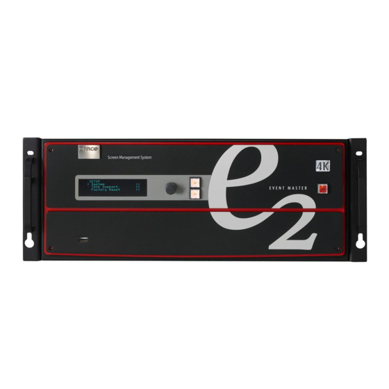
Page 46: Front Panel
About front panel See image 4-1 for an illustration of the front panel of Event Master E2 (and E2 Jr.) and S3–4K (and S3–4K Jr.) series processors. See image 4-2 for an illustration of the front panel of the Event Master EX processor. -
Page 47: Menu Navigation Controls
4. Hardware orientation Menu navigation controls The navigation in the menus is assumed by three controls: • Turn the ADJUST knob to scroll through the menu items on the screen. Turn the knob counter-clockwise to scroll down. Turn the knob clockwise to scroll up. A navigation cursor (>) to the left of a menu item indicates the position of the scroll bar, as shown in the following illustration. -
Page 48: Rear Panel
About rear panel See image 4-5 for an illustration of the rear panels of the Event Master E2 and S3–4K series processors. See image 4-6 for an illustration of the rear panels of the Event Master E2 Jr. and S3–4K Jr. series processors. See image 4-7 for an illustration of the rear panel of the Event Master EX processor. - Page 49 – Input cards (HDMI/DP, SDI, DVI) Outputs cards (DVI, SDI) Multiviewer card (HDMI) The S3–4K Jr. comes with a single power supply; a redundant power supply is optional. Image 4-7 EX rear panel AC connector RJ-45 connector for 10/100 BaseT Ethernet communications...
-
Page 50: Ethernet Port
AC connectors Event Master E2, E2 J., S3–4K, and S3–4K Jr. series processors are equipped with two redundant power supplies. During normal operation the load is shared equally by both supplies. If one supply fails, the second carries the whole load. Two AC Connector are provided to connect Event Master series processors to your facility’s AC power source through the supplied power cords. - Page 51 Key frame effects On an E2 and E2 Jr. units, the VPU cards are not accessible through the rear panel. On S3–4K and S3–4K Jr. units, slots 2 and 3 are reserved for the VPU cards. The EX expansion box has no VPU cards.
- Page 52 4. Hardware orientation The following sections describe each type of card in detail: • "HDMI Output Card", page 57 • "SDI Output Card", page 58 Multiviewer (MVR) card The Multiviewer card is physically identical to the HDMI output card, but when it’s plugged in the last slot it operates as a Multiviewer (MVR), supporting two (2) HD outputs.
-
Page 53: Sdi Input Card
4. Hardware orientation SDI Input Card General This card provides 4 BNC connectors supporting Single Link, Dual Link and Quad Link signals, in SD, HD, 3G-SDI and 6G-SDI Ultra HD (UHD) formats. This card currently supports up to 3G-SDI formats. 6G-SDI formats may be supported in a future software release. - Page 54 4. Hardware orientation Specifications • Supported format: Signal type Min. BNC Standard Examples channels connector number per card SMPTE 259M-C 480i, 576i ( NTSC/PAL ) SMPTE 292M 1920x1080 @ 59.94i/50i 1920x1080psf @ 23.98/24/25/29.97/30 720x480 @ 60p/50p SMPTE 424M 1920x1080 @ 60p/50p Barcolink 1920x1200 @ 60p/50p 4K / UHD...
-
Page 55: Dual Link Dvi Input Card
4. Hardware orientation Dual Link DVI Input Card General The dual link DVI input card includes two DVI-I dual-link connectors that can support a single or dual-link DVI video signal. Although the DVI-I connectors includes pins that support analog signals, the DVI card doesn’t support analog signals. - Page 56 4. Hardware orientation Specifications • DVI 1.0 Specification • Maximum H Active: 4,096, Maximum V Active: 3,072 • Supported format: All single link DVI formats up to 165 MHz All dual link DVI formats up to 330 MHz 4K/UHD Supported: 3,840x2,160/ 23.98/24/25/29.97/30 input via 1x DVIDL, 2x DVISL (L and R half) or 4x DVISL (quadrants) 3,840x2,160/ 50/59.94/60 input via 2x DVIDL (L and R half) or 4x DVISL (quadrants) 4,096x2,160/ 23.98/24/25/29.97/30 input via 2x DVISL (L and R half) or 4x DVISL (quadrants)
-
Page 57: Hdmi/Displayport Input Card
4. Hardware orientation HDMI/DisplayPort Input Card General The HDMI/DisplayPort input card has two 19-pin HDMI connectors which can support a HDMI video signal, and two 20-pin Display- Port connectors supporting DisplayPort video signal. The figure below illustrates the HDMI/DisplayPort input card’s rear panel connectors: Image 4-10 HDMI/DisplayPort Input Card Rear Panel Displayport connector —... - Page 58 4. Hardware orientation DisplayPort specifications • DisplayPort per 1.1a specifications • Supported format: formats up to 2,560x1,600@60 and 3,840x1,200@60 (30 bits) 4K/UHD Supported: 3,840x2,160/ 23.98/24/25/29.97/30 via 1x DP, 2x DP (L and R half) or 4x DP (quadrants) 3,840x2,160/ 50/59.94/60 via 2x DP (L and R half) or 4x DP (quadrants) 4,096x2,160/ 23.98/24/25/29.97/30 via 2x DP (L and R half) or 4x DP (quadrants) 4,096x2,160/ 50/59.94/60 via 2x DP (L and R half) or 4x DP (quadrants) EDID version 1.3 compatible...
-
Page 59: Quad Channel Displayport Output Card
4. Hardware orientation Quad Channel DisplayPort Output Card General The quad channel DisplayPort output card has four 20-pin DisplayPort connectors that can provide a DisplayPort signal. The figure below illustrates the DisplayPort output card’s rear panel connectors: Image 4-11 Quad Channel DisplayPort Output Card Rear Panel DP connector —... - Page 60 4. Hardware orientation Specifications • DisplayPort per 1.2 specification • Pixel clock up to 620 MHz Max pixel clock at 24 bits/pixel = 620 Mpix/sec Max pixel clock at 30 bits/pixel = 576 Mpix/sec Max pixel clock at 36 bits/pixel = 480 Mpix/sec •...
-
Page 61: Hdmi Output Card
4. Hardware orientation HDMI Output Card General The HDMI output card has four 19-pin HDMI connectors which can provide a HDMI video signal. The figure below illustrates the HDMI output card’s rear panel connectors: Image 4-12 HDMI Output Card Rear Panel HDMI connector —... -
Page 62: Sdi Output Card
4. Hardware orientation SDI Output Card General The SDI Output Card has 4 BNC connectors that can support Single Link, Dual Link and Quad Link signals, in SD, HD, 3G-SDI and 6G-SDI Ultra HD (UHD) formats. This card currently supports up to 3G-SDI formats. 6G-SDI formats may be supported in a future software release. - Page 63 4. Hardware orientation Specifications • Supported format: Signal type Min. BNC Standard Examples channels connector number per card SMPTE 259M-C 480i, 576i ( NTSC/PAL ) SMPTE 292M 1920x1080 @ 59.94i/50i 720x480 @ 60p/50p SMPTE 424M 1920x1080 @ 60p/50p Barcolink 1920x1200 @ 60p/50p 4K / UHD 3840x2160/23.98/24/25/29.97/30 input via 4x HD-SDI (quadrants)
-
Page 64: Expansion Link Card
S3–4K Jr. 1, 2 E2 Jr. and S3–4K Jr. do not have Link cards, but these models can be upgraded with Link cards, which would go into the same slots as the Link cards on the E2 and the S3–4K. -
Page 65: Vpu Card
The VPU cards are not accessible from the rear panel on E2 and E2 Jr. units. Even though they have no external connections, slots 2 and 3 are reserved for VPU cards on S3–4K and S3–4K Jr. units. The EX expansion box can have a combination of Input and Output cards, or it can have two VPU cards. - Page 66 4. Hardware orientation R5905948 EVENT MASTER DEVICES 17/07/2017...
-
Page 67: Front Panel Menu Orientation
About this chapter This chapter describes the front panel menus of the Event Master units (E2 and S3 series), including how they are accessed and the functions or parameters that are available. The menu trees are presented in block diagram format throughout the chapter. -
Page 68: Power-Up Initialization
5. Front Panel Menu orientation Power-up initialization Initialization Ensure that your system is properly installed and cabled. Make sure the two AC Connector are properly connected to your facility’s AC power source through the two supplied power cords. Locate the power button on the front panel and turn power On. While the system is initializing, the front-panel buttons light up one at a time, and the following message is displayed. -
Page 69: Front Panel Menu Tree
5. Front Panel Menu orientation Front Panel menu tree About this section The diagram below illustrates the Front Panel menu tree of the Event master devices. Please use this diagram for reference as you learn how to operate the system. Menu tree Image 5-2 R5905948 EVENT MASTER DEVICES 17/07/2017... -
Page 70: Using Menu System
5. Front Panel Menu orientation Using menu system General This section describes the conventions for using the menu system of the Event Master devices. For reference, the following illus- tration shows the System Menu. Image 5-3 System menu The unit’s display screen is four lines high. Throughout this chapter, entire menus are shown for ease of reference, unless otherwise noted. - Page 71 5. Front Panel Menu orientation Answering a menu query The SEL button is used to answer Yes to certain menu queries. The ESC button is used to answer No to menu queries. Sometimes the two buttons are appropriate for answer to a menu queries. The following illustration shows an example of a menu query. Image 5-4 Validation error message Edit name...
-
Page 72: About Status Menu
5. Front Panel Menu orientation About Status menu General The Status Menu is the Event Master series processor’s top-level menu, which appears by default at system startup. This menu provides system name, Unit ID, Genlock status and unit IP address. The following figure illustrates a sample Status Menu. Press the ESC button when the Setup menu is displayed allows to return in the Status menu. -
Page 73: About Setup Menu
5. Front Panel Menu orientation About Setup menu General The Setup menu, shown in the following illustration, is the menu from which you access all operational menus. To display the Setup menu, press the SEL button on the front panel when the Status menu is displayed, or press the ESC button to go back from a submenu (one level for each time you press the button). -
Page 74: About The System Menu
5. Front Panel Menu orientation About the System menu General The System Menu, shown in the following illustration, allows you to view and change settings such as HDCP status and Ethernet options. In this menu you can also backup or restore Event Master unit configuration, obtain diagnostic information, adjust the intensity or lock the display screen. -
Page 75: System Menu > Black Invalid
5. Front Panel Menu orientation System menu > Black Invalid General The Black Invalid system setting determines whether the output is black when connected to a signal it cannot process. Black Invalid is either On or Off. The default setting is On. This is a global setting, applicable to all outputs. R5905948 EVENT MASTER DEVICES 17/07/2017... -
Page 76: System Menu > Usb Device (Backup/Restore)
5. Front Panel Menu orientation System menu > USB device (Backup/Restore) General The unit’s front panel contains a USB port that you can use to connect a flash drive to the Event Master unit. The flash drive must be formatted to use the FAT32 file system. For formatting instructions, refer to section Formatting the flash drive in the chapter "Upgrading firmware using the USB port", page 256. - Page 77 5. Front Panel Menu orientation The USB Restore Config submenu appears, as shown in the following illustration. Image 5-12 3. Press SEL and scroll through the list of configuration files. When you locate the file you want, press SEL again. 4.
- Page 78 5. Front Panel Menu orientation a) On your PC’s C: drive, locate the Barco folder. Image 5-13 b) In that folder, locate the Event Master Toolset folder that corresponds to the current version you are using. Image 5-14 c) Then locate the folder called “wvp_9876”.
-
Page 79: System Menu > Ethernet
5. Front Panel Menu orientation System menu > Ethernet General The Ethernet submenu allows the user to view and change certain Ethernet settings. Image 5-17 Using this menu, you can: • Query the DHCP server for a valid IP address, or turn off this feature. •... - Page 80 5. Front Panel Menu orientation If you press ESC at any time before accepting your final change, all your edits will be removed, and the original values restored. R5905948 EVENT MASTER DEVICES 17/07/2017...
-
Page 81: System Menu > Vfd Brightness (Display Brightness)
5. Front Panel Menu orientation 5.10 System menu > VFD brightness (display brightness) General The VFD Brightness submenu adjust the intensity of the front panel vacuum fluorescent display (VFD) screen. The adjustment range is +0 to +6, with +6 being the brightest. The default setting is +3. R5905948 EVENT MASTER DEVICES 17/07/2017... -
Page 82: System Menu > Diagnostics
5. Front Panel Menu orientation 5.11 System menu > Diagnostics General The following illustration shows the Diagnostics submenu, which you access from the System menu. Image 5-19 The Diagnostics options allow a user to check if the Event Master unit is functioning normally. Front panel and card operations can be checked. - Page 83 5. Front Panel Menu orientation Cards Image 5-21 The Card Slot test will perform a variety of diagnostics for an individual card or for all cards. This is a quick way to determine if a given card is having a problem. After selecting a Slot number or choosing All cards to be tested, the following message will be displayed. Image 5-22 Pressing SEL to continue will start the diagnostic testing.
- Page 84 5. Front Panel Menu orientation To see more detailed results of diagnostic testing, run diagnostics from the Event Master Toolset Software. For details on this fonction, please refer to chapter "Settings Menu > Web App area > Dashboard", page 207 Temperature Image 5-26 The DIAGNOSTIC TEMPERATURE menu will show real time measurements for the System, Motherboard and all card slots.
-
Page 85: System Menu > Lock Front Panel
5. Front Panel Menu orientation 5.12 System menu > Lock front panel General When the Event Master unit’s front panel is locked, button presses have no effect. In the locked mode: • All button presses (including Power ON/OFF button) and all turns of the ADJUST knob are ignored. •... -
Page 86: Using The Tech Support Menu
The US Customer Support telephone number. This number is accessible from 6 a.m. to 10 p.m. (PST), 7 days per week. The European customer support number is: 0800-90-0410. In China call: 40088-22726. All other regions, call your local Barco support. -
Page 87: Restoring Factory Default Settings
5. Front Panel Menu orientation 5.14 Restoring Factory Default Settings General As shown in the following illustration, two options in the Setup Menu allow you to restore the Event Master unit to its factory default condition. Image 5-31 The following attributes constitute a factory default condition: •... -
Page 88: Firmware Upgrade
5. Front Panel Menu orientation 5.15 Firmware Upgrade General The Event Master unit provides two options for upgrading firmware: • Using the USB port on the front panel. • Using the Web Interface. Please refer to the chapter "Settings Menu", page 201 for the instructions on how to perform firmware upgrades through the USB memory or the web interface. -
Page 89: Save All
5. Front Panel Menu orientation 5.16 Save All General Save All on the Setup menu saves your custom configuration parameters in non-volatile memory. If you save the system state, these parameters are restored the next time you power up the Event Master unit. If you do not use this function, your custom settings are not restored during the next system power up sequence. - Page 90 5. Front Panel Menu orientation R5905948 EVENT MASTER DEVICES 17/07/2017...
-
Page 91: Em Gui Orientation
Ethernet connection. The program provides a step-by-step approach to configure, program, setup the dedicated Multiviewer and manage system functions. Some screenshots and descriptions provided in this chapter may not accurately reflect the released software. Barco will update the documentation in a timely manner to mirror the released software R5905948 EVENT MASTER DEVICES 17/07/2017... - Page 92 6. EM GUI orientation Overview • General requirements • Download of Event Master Toolset Software • Software installation • Starting up • Screen layout presentation • Controls • Configuration Menu • Configuration Menu > Network resource area • Configuration Menu > System diagram area •...
-
Page 93: General Requirements
6. EM GUI orientation General requirements System requirements for Microsoft Windows Minimum hardware specifications : • Intel I5, 2 core • 4GB RAM • Free hard disk space: 600 MB • WSXGA resolution (1280 x 1024) • Fixed Ethernet connection Software •... -
Page 94: Download Of Event Master Toolset Software
Download of Event Master Toolset Software Overview The Event Master Toolset Software can be downloaded for free from Barco’s website, (URL: http://www.barco.com). The software is also available on myBarco and login to get access to secured information. Registration is necessary. -
Page 95: Software Installation
Currently the EM GUI is available for PCs with Microsoft Win7 or Microsoft Win10, and Apple MACs with OS X. The software will run on other Microsoft and Mac operating systems, but currently Barco only supports software installations with Win7 (or Win10) and OS X computers. Linux version of the software will be available in a future release. -
Page 96: Starting Up
1. Double click on the Event Master Toolset Software icon on your desktop click Start → All programs → Barco Folsom → Event Master Toolset Rev x.x (Build xxxxx) The software starts up with the same look and feel as when it was closed before. -
Page 97: Screen Layout Presentation
6. EM GUI orientation Screen layout presentation General The user interface is organized around a Menu Navigation bar at the left of the screen and a Working area in the rest of the screen. The layout of the screens is similar throughout the GUI. In order to explain the layout, we will examine the start-up screen of the Configuration Menu and describe the different components. - Page 98 6. EM GUI orientation Selection area The selection area allows the users to select the System, Device or inputs that will be used. Diagram area In the middle, is the Diagram area where the system, Screens and Multiviewer are represented graphically. Configuration area On the right hand side, is the configuration area where users perform all needed adjustments.
-
Page 99: Controls
6. EM GUI orientation Controls General Edit box Edit box is used to edit the values or names. Image 6-2 Properties: • By double clicking, the background changes to a dark blue color indicating that modifications can be made. • The cursor is placed on the last character. -
Page 100: Configuration Menu
6. EM GUI orientation Configuration Menu General The Configuration menu is the module used to edit the Presentation Systems (creation, modification, deletion). This page is the first page that appears when you launch the EM GUI software. The user will use this page to add or remove devices to the selected system. The user also could modify the parameters of these devices like inputs, backgrounds, outputs and destinations. - Page 101 6. EM GUI orientation Adjustment area There are several panels in this area: Adjustment, Input/Background, Output/MVR and Destinations. Each panel displays the list of items currently defined in the system. The user can also add or delete and define more items.
-
Page 102: Configuration Menu > Network Resource Area
6. EM GUI orientation Configuration Menu > Network resource area General This part of the System configuration page allows listing devices available on the local network and identifying them. Description The panel in this area has three tabs: • Discovered: Lists all of the devices discovered on the local network, regardless of the selected System. - Page 103 6. EM GUI orientation Image 6-7 How to manually add a device into the selected system To manually add a device, use the “Manual Add” section. 1. Enter the IP address. 2. Press the “Add” button. Image 6-8 Unit is added and retrieves the available configuration in the Device. R5905948 EVENT MASTER DEVICES 17/07/2017...
-
Page 104: Configuration Menu > System Diagram Area
6. EM GUI orientation Configuration Menu > System diagram area General The system is represented graphically in this part of the System configuration page. It is here that the user can select a system (or create a new one), or select a system element ( inputs, outputs, destinations …) Description The diagram area graphically represents the devices and destinations that compose the system. - Page 105 6. EM GUI orientation Image 6-10 A confirmation window appears. 2. Click on OK. The tab is removed. How to select device in the system 1. Click on the area situated below the Event Master series processor graphic representation. Image 6-11 Device selected The device is selected.
- Page 106 6. EM GUI orientation Selecting a device or a destination in the Diagram allows the Adjustment area to display to display the pa- rameters corresponding to the device or destination. See Adjust Tab in the section "Configuration Menu > Adjustment area", page 104. R5905948 EVENT MASTER DEVICES 17/07/2017...
-
Page 107: Configuration Menu > System Modifier Area
6. EM GUI orientation 6.10 Configuration Menu > System modifier area General General parameters concerning the selected system are accessible in this area. The user can select the system’s preset conflict mode, the native rate, and genlock mode. Description Image 6-13 •... -
Page 108: Configuration Menu > Adjustment Area
6. EM GUI orientation 6.11 Configuration Menu > Adjustment area General Situated on the right hand side of the screen is the Adjustment area. In this area the user can define and adjust unit specific param- eters, inputs, backgrounds, outputs, multiviewer outputs and destination affected to the selected system. Description There are 4 tabs in this area: •... -
Page 109: Configuration Menu > Adjustment > Unit Configuration
Each EMP model has a standard static IP Address. • E2 (and E2 Jr.) = 192.168.0.175 • S3–4K (and S3–4K Jr.) = 192.168.0.176 • EX = 192.168.0.185 If a DHCP IP address is required, the unit can be set to accommodate that too. - Page 110 6. EM GUI orientation The IP Address is changed by double-clicking on the STATIC setting and assigning an allowed configuration. For details on Network configurations we refer to industry standard. Setup tab: • Unit ID: Unique unit identification number. • Front Panel: Locks or unlocks the front panel.
-
Page 111: Configuration Menu > Adjustment > Input Configuration
On the E2 model, the input cards occupy slots 3 through 10 and are right justified to slot 10. On the S3–4K model, the input cards occupy slots 4 through 6 and are right justified to slot 6. If there is an empty input slot between two input slots, all input cards to the left of the empty slot are marked with red. Red indicates that although the cards will operate properly, inputs from these cards will not be available at the Multiviewer. - Page 112 6. EM GUI orientation Image 6-15 Examples of valid 3D* Inputs: Image 6-16 (*) S3D inputs will be supported in a future software release. Input connector colors Not assigned and no input signal is detected Not assigned to any Source or an input, but a signal has been detected Assigned to a source or an input and an input signal is detected Assigned to a source or an input, but an input signal is not detected Input configuration menu description...
- Page 113 6. EM GUI orientation This menu provides: • A list of all the inputs already created on the system (e.g. Cam 1, Input2). • A button to automatically allocate all unassigned input connectors to an input. • A button to automatically allocate all LIVE input connectors (GREEN) to an input.
- Page 114 6. EM GUI orientation 2. In the System diagram area, click on the connector(s) that need to be assigned. Note: If the input signal is 4K provided by the 4 SDI connectors, 4 SDI connectors need to be selected. Connector(s) is immediately highlighted in blue. 3.
- Page 115 6. EM GUI orientation Input adjustment panel description The input adjustment panel is divided in four sections. • Main page • Format & Timing • Color Adjustment • Contact Information R5905948 EVENT MASTER DEVICES 17/07/2017...
- Page 116 6. EM GUI orientation Input adjustment panel > Main page This menu is available in two versions according to the input type: • DVI, HDMI and DisplayPort input types • Name: Edits the name of the input configuration. • Sync Status: Detects a good video sync. •...
- Page 117 6. EM GUI orientation • EDID All inputs can have an EDID (Extended Display Identification Data) set according to its connector capacity. The currently set EDID is visible in the Current box. Format: The drop-down menu with its search function provide a way to select any of the available VESA or SMPTE standard EDIDs as well as a frame rate.
- Page 118 6. EM GUI orientation Input adjustment panel > Format & Timing This is a status and informational menus. No adjustments can be done on this Format and Timing panel. • Format: Video format of the input • H Total: Total pixel count per line •...
- Page 119 6. EM GUI orientation Input adjustment panel > Contact Information This menu allows for the user to enter contact information for easy identification. R5905948 EVENT MASTER DEVICES 17/07/2017...
-
Page 120: Configuration Menu > Adjustment > Background Configuration
6. EM GUI orientation 6.14 Configuration Menu > Adjustment > Background Configuration General Assigning input connectors to backgrounds is very similar to creating Inputs as it was discussed in the previous section. Therefore, the menus are also very similar and for the sake of simplicity the same menus are not going to be presented in this section. One of the differences between Inputs and backgrounds is in the number of connectors that can be assigned to each one. - Page 121 6. EM GUI orientation Please note that connector assignments for the backgrounds cannot change from what is shown in the dia- gram. The system wiring needs to reflect the same order R5905948 EVENT MASTER DEVICES 17/07/2017...
-
Page 122: Configuration Menu > Adjustment > Output Configuration
On the E2 model, the output cards occupy slots 11 through 13 and right justified to slot 13. On the S3–4K model, the output cards occupy slots 7 through 8 and right justified to slot 8. If there is an empty output slot, all output cards to the left of that empty slot will be red. Red indicates that although the cards will operate properly, outputs from these cards will not be available at the Multiviewer. - Page 123 6. EM GUI orientation Image 6-20 • 4 x SDI 1920x1080 • 4 x HDMI 1920x1080 or 2048x1080 on 1 card • 4 x HDMI 1920x1080 or 2048x1080 two cards • The top 2 x HDMI at 1920 x 2160 or 2048 x 2160 at max 60P •...
- Page 124 6. EM GUI orientation This menu provides: • A list of all the outputs already created on the system (e.g. Output1) • A button to automatically allocate all unassigned output connectors to an output. • A button to manually allocate output connector(s) to an output. •...
- Page 125 6. EM GUI orientation How to add Output Outputs configurations can be added manually to unassigned connectors. 1. Click on the Add Output button. The Add Output button is replaced by the Done Adding button (highlighted in blue). 2. In the System diagram area, click on the connector(s) that need to be assigned. Note: If the output is 4K provided by the 4 SDI connectors, the 4 SDI connectors need to be selected.
- Page 126 6. EM GUI orientation Image 6-23 The output adjustment panel is displayed. Output adjustment panel description The output adjustment panel is divided in three sections • Main page • Format & Timing • Connector R5905948 EVENT MASTER DEVICES 17/07/2017...
- Page 127 6. EM GUI orientation Output adjustment panel > Main page • Auto Configure Output format: Selects the output format will be set to match the format contained in the EDID of the display device connected to the corresponding output(s). • Name: The name of the output configuration can be edited in this field.
- Page 128 6. EM GUI orientation Output adjustment panel > Timing Menu • Format: Selects the video format of the output configuration from the drop menu. This is the same adjustment as in the previous menu. • H Total: Adjusts (in pixels) the total pixel count per line for the selected output.
- Page 129 6. EM GUI orientation • Color/Sample/Bit: Adjusts the color space (RGB or YCbCr), sampling rate (4:4:4 or 4:2:2) and bit depth (8, 10, or 12) of the output signal. Depending on the EDID of the connected device the drop-down list would populate with compatible settings.
-
Page 130: Configuration Menu > Adjustment > Destination Configuration
6. EM GUI orientation 6.16 Configuration Menu > Adjustment > Destination Configuration General Output configurations that are created in the previous menus are assigned to destination in the Destination Panel. Description Destination configuration menu is accessed by clicking on the Destination tab. This menu provides: •... - Page 131 6. EM GUI orientation Widescreen destinations can be downscaled by the Aux and based on the capacity it can accommodate up to eight (8) outputs worth of widescreen. Color codes Screens and Aux are represented graphically in the Diagram area. Green: Output(s) have been assigned to the destination Yellow: Output(s) have not been assigned to the destination.
- Page 132 6. EM GUI orientation Outputs can be added in reverse order, or even un even order allowing for correction of wrongly connected wires Image 6-25 How to delete Destination 1. Click on the Delete Destination(s) button The Delete Destination(s) button is replaced by the Delete Selected button (highlighted in red) and the unit diagram is greyed out, except the area dedicated to destinations (Screen and Aux).
- Page 133 6. EM GUI orientation Image 6-27 The Destination adjustment panel is displayed. Destination adjustment panel description The Destination adjustment panel is divided in three sections: • Assign • Output • Wide R5905948 EVENT MASTER DEVICES 17/07/2017...
- Page 134 8. An E2 Jr. has a single Bank of 8 Mixing Layers for a total of 8 Mixing Layers or 16 Single Layers (16L). An S3–4k has 1 bank of 4 Mixing Layers for a total of 4 Mixing Layers or 8 Single Layers (8L). These 8 Mixing Layers can be assigned to Destinations, using up to 4 Outputs (1 Bank).
- Page 135 Mixing Layer Type Maximum number of Single Layers E2 Jr. S3–4K S3–4K Jr. 2K HD Dual Link Layers need to be assigned to destinations before sources can be added to the destination. Output menu The Output Menu contains four sub-menus: Main, Color, Timing and Connector proprties.
- Page 136 6. EM GUI orientation Output menu – Main submenu Operate similarly to the Output adjustment panel > Main menu. • Test pattern: Turns the Test Patterns ON and select the desired type. The default setting is OFF. Test pattern types: –...
- Page 137 6. EM GUI orientation Output menu – Color submenu The Output Effects Submenu adjusts color variable of the output image, such as contrast and brightness, saturation, hue and gamma corrections. • The RGB Contrast and Brightness settings are adjustable. The Overall adjustment has a range of 50 to 150. The individual Red/Green/Blue adjustments have a range of 25 to 150.
- Page 138 6. EM GUI orientation Output menu – Timing submenu Operate similarly to the Output adjustment panel > Timing menu. • Format: Selects the video format of the output configuration from the drop menu. This is the same adjustment as in the previous menu.
- Page 139 6. EM GUI orientation HDMI Connector submenu • Color/Sample/Bit: Choices are: – RGB/4:4:4/8 – YCbCr/4:4:4/8 – RGB/4:4:4/10 – YCbCr/4:4:4/10 – RGB/4:4:4/12 – YCbCr/4:4:4/12 – YCbCr/4:2:2/12 • Color Range: Choices are: RGB, Reduced Range (Values 16–235, television and movies) RGB, Full Range (Values 0–255, computer monitors) SMPTE, Full Range SMPTE, Reduced Range •...
- Page 140 6. EM GUI orientation Data-doubling submenu—Basic Mode • Canvas H: This is the horizontal size of the canvas, measured in pixels. The edit box allows the user to adjust this size. • Canvas V: This is the vertical size of the canvas, measured in pixels.
- Page 141 6. EM GUI orientation Data-doubling submenu—Expert Mode The top part of the panel is the same in Expert Mode as it is in Basic Mode. Expert Mode, however, offers greater control over horizontal and vertical Offset and Size. Expert Mode also allows the user to add Outputs without increasing the canvas size and to place those Outputs anywhere within the canvas.
- Page 142 6. EM GUI orientation Feathering submenu • Canvas shows the actual pixel ratio for the full blend. • Select the region where feathering will be performed. All edges can be separately selected and have a different value of Feather and Gamma. The adjustment can be made my moving the slider, entering the value manually in the box or click on the plus and minus.
-
Page 143: Configuration Menu >Linking
Any second unit can be added, it only needs to have a separate Unit ID. Change the Unit ID of each system to be different. The default Unit ID is 0 on all Event Master presentation switchers—E2, S3-4K, and EX. On one of the E2s change the Unit ID to 1 from the front panel, or by temporarily adding them as separate systems. - Page 144 How to Link an E2 Unit and an S3–4K Unit Each E2 comes equipped with two Link cards, always located in slots 1 and 2. Each S3–4K has a single Link card in slot 1. Link cards are identified by a yellow stripe at the top. Make sure to use the locking mechanism and then push each cable until it locks in place.
- Page 145 4. Then drop the S3–4K in the GUI. You will be presented the option to add as a new system, add as a master, or add as a slave. An S3–4K can be added as a Master or Slave to an E2.
- Page 146 How to Link an E2 Unit and two S3-4K Units Each E2 comes equipped with two Link cards, always located in slots 1 and 2. Each S3–4K has a single Link card in slot 1. Link cards are identified by a yellow stripe at the top. Make sure to use the locking mechanism and then push each cable until it locks in place.
- Page 147 4. Drop the S3–4K #1 in the GUI. You will be presented the option to add as a new system, add as a master, or add as a slave. An S3–4K can be added as a Master or Slave to an E2.
- Page 148 1. Start the Event Master Toolset version 4.1 or higher. 2. Make sure that the E2, the S3–4K, and the EX are discovered on the network and that they have different Unit IDs. 3. Drop the E2 in the GUI.
- Page 149 How to Link an S3-4K Unit and an EX Unit with two VPU cards To add up to 16 Single or two 4K Mixing Layers to a system, an S3-4K Unit can be linked to an EX Unit with two VPU cards. Each S3–4K has a single Link card in slot 1, identified by a yellow stripe at the top.
- Page 150 E2 Jr. and the S3–4K Jr. units do not ship with Link cards, but they do not support linking as an upgrade option. To support linking with an E2 Jr. or an S3–4K Jr. unit, you may purchase an Event Master Link card (P/N R9004746) and install it in Slot #1 of the unit.
- Page 151 4. Drop the second unit in the GUI. You will be presented the option to add as a new system, add as a master, or add as a slave. An S3–4K can be added as a Master or Slave to an E2.
-
Page 152: More Information
More information For more information on how to prevent cable and connector damage on the Link Cards for E2 and S3–4K, see InfoT-1294: Cable and Connector Damage on the Link Cards for E2 Series and S3–4K Series Presentation Switchers on the Technical Downloads tab on the E2 Full-sized Event Master processor web page (URL: https://www.barco.com/en/Products/Image-processing/Presentation-... -
Page 153: Programming Menu
6. EM GUI orientation 6.18 Programming Menu General The programming page is where the event is set up and everything comes together. Users can define sources from inputs, assign layers and backgrounds into screens and create User keys and presets and more. Once programmed and defined this is where the show is played back as well. -
Page 154: Programming Menu > Resources Area
6. EM GUI orientation 6.19 Programming Menu > Resources area General This part of the Programming page allows users to manage the available input resources. Sources are created and defined from the available Inputs that were defined on the System Configuration page. From Release 1.5 there is Still Stores for Sources, Still Stores for Backgrounds and Destinations for re-entry. - Page 155 6. EM GUI orientation • Definition: A layer is one image stacked on top of another or a background. • Features: Each mixer layer has two layers, Preview and Program. For complete flexibility, each layer can be assigned to either PIP or Key functionality.
- Page 156 6. EM GUI orientation Input, Sources and layer example Image 6-40 Source Area description In this menu, Sources defined in the Configuration menu are assigned to destinations via drag and drop procedure. Each input has minimum one Source file, several can be created via copy original (Plus Icon) or copy file (Double Page Icon). There are 2 tabs in this section: •...
- Page 157 6. EM GUI orientation Inputs (List view) Inputs (List view) • Resolution: This is the resolution of the Input signal. • The LED color indicates the status of the input: Red: Sync is missing or invalid format. Green: Sync is valid. •...
- Page 158 6. EM GUI orientation Inputs (Thumbnail view) • Behavior is similar to the List View mode (see above). By clicking in thumbnail area images can be imported using the file picker menu. The picker can select pictures with the BMP, JPG or PNG format.
- Page 159 6. EM GUI orientation Stills (List view) Stills (List view) • Stills can be added from external source of the GUI computer in the PNG format. • Name that can be changed by double click action and then the resolution of the Stillstore. •...
- Page 160 6. EM GUI orientation Destination Destination (List view) Destination (Thumbnail view) The Destinations can be used as a source in Layers provided they have the capacity to fit. Up to 2K resolutions on SL, up to 4096 x 1200 / 2560 x 1600 for DL and 4K / 8192 x 1200 for 4K Scaler Mode. How to delete sources The delete process is similar for all lists with more than one entry.
- Page 161 6. EM GUI orientation The Delete Source(s) button turns in red and the delete icon (“x”) appears next to the copy icon on each element of the source list. Image 6-41 Delete Selected Input sources 2. Select the sources that you desire to delete and click the Delete Source(s) button. The selected sources are removed.
- Page 162 6. EM GUI orientation Sources are displayed without their associated Inputs. Image 6-42 Hide Input(s) checkbox Background In this menu, Backgrounds defined in the Configuration menu are assigned to destinations via drag and drop procedure. Backgrounds and Destinations need to have the same resolution without the Destinations eventual blend overlap. For example, if a background is defined as an input with 3840 x 1080, then the destination must also have the total resolution of 3840 x 1080.
- Page 163 6. EM GUI orientation Background (List view) • Name: This is the Name of the Input as created in the Configuration of the system. • Resolution: This is the resolution of the Input signal. • The LED color indicates the status of the input: Red: Sync is missing or invalid format.
- Page 164 6. EM GUI orientation Background Stills (List view) • Name: This is the Name of the Stillstore as created in Background menu. Name can be changed by double click action. • Resolution: This is the resolution of the Stillstore. • [Disk Icon] Indicates the memory required for the Stillstore.
- Page 165 The Input > Backgrounds subtab allows the Event Master series processor to use Backgrounds as Inputs. This subtab can be used on any Event Master processor, but it is especially useful on a limited-resource processor, such as an S3–4K Jr. processor. An Input defined as a Background can now be used as a Background, or as a source on an AUX Destination or Screen Destination layer.
- Page 166 6. EM GUI orientation To use a Background as an Input, follow this procedure. Go to the Programming menu. Go to the Input tab of the Resources area, and then go to the Backgrounds subtab of the Input tab. Drag a Background from the list on the Backgrounds subtab and drop it on any Screen or AUX Destination in the Programming Diagram area that has at least one source layer assigned to it.
-
Page 167: Programming Menu > Diagram Area
6. EM GUI orientation 6.20 Programming Menu > Diagram area General The middle of the Programming Page is the Programming diagram area where the Program, Preview and AUX screens are com- posed. Description Each Program/Preview screen can be viewed individually or all of the screens can be shown simultaneously by selecting the corre- sponding tab on the top of the Program window. - Page 168 6. EM GUI orientation Image 6-44 Next a source from the Input panel on the left hand side can be dragged into the layer. Image 6-45 Alternatively, an Input or a source can be dragged into the Preview screen directly as long as there are available layers. Image 6-46 If the available layer is already in Preview, then the source will immediately be assigned to that layer.
- Page 169 6. EM GUI orientation Scaler mode for layers are set in the Configuration Page, towards the bottom. Z-Order The layer priority (z-order) is based by the order they are added in destination menu. The layers that are added first have the lowest priority.
-
Page 170: Programming Menu > Layer Modifier Area
6. EM GUI orientation 6.21 Programming Menu > Layer Modifier area General This area is specifically for layer adjustments. Description The area is broken up into several sub areas. The left side is for alignment, priority, size and position of the layer. Middle is for layer transition. - Page 171 6. EM GUI orientation Priority Image 6-50 Moves the selected layer up in priority and swaps with the layer previously above. Moves the selected layer to the top of the priority and swaps it with the layer previously on top. Moves down in priority and swaps the z-order of the selected layer with the layer previously below.
- Page 172 6. EM GUI orientation Full Screen Vertical takes the selected PIP(s) to full screen, using the source’s height as the guide. If borders are on, they will be taken into account so that they are visible. Full Screen Horizontal takes the selected PIP(s) to full screen, using the source’s width as the guide. If borders are on, they will be taken into account.
- Page 173 6. EM GUI orientation Preview transitions to Program according at the rate indicated in the rate box following the s-curve pattern. The layer on Program does NOT fade in preview at the same time. The layer on Program appears in Preview when the transition is completed. Instantly transitions the Preview to Program Move Enables moves for selected that have one or more keyframes.
-
Page 174: Programming Menu > Adjustment Area
6. EM GUI orientation 6.22 Programming Menu > Adjustment area General Situated on the right hand side of the screen is the Adjustment area. In this area users can configure Layers and Sources and create User keys and Presets. Description There are several tabs in this area: •... -
Page 175: Programming Menu > Adjustment Area > Layer Configuration
6. EM GUI orientation 6.23 Programming Menu > Adjustment area > Layer configuration General In the Layer menu, users can manage the layer in the selected destination and update its attributes. Layer configuration menu description Layer configuration menu is accessed by clicking on the Layer tab. This menu provide: •... - Page 176 6. EM GUI orientation How to access the layer adjustments Adjustments to layers are performed in the “Adjust” panel: 1. Select the layer from the list Select the layer from the preview canvas. The layer is selected. Image 6-59 When the layer is selected and is visible on the canvas, it will have a blue highlight around the layer. 2.
- Page 177 6. EM GUI orientation Image 6-60 Once the two keyframes are defined, the PIP can move between the two positions by pressing the green arrow buttons. The rate for the movement is adjusted by changing the number in the corresponding box. Any of the two keyframes can be deleted when the keyframe is highlighted and by pressing the “Delete KF”...
- Page 178 6. EM GUI orientation The following functions are provided: • Enables or disables the PIP’s shadow. • H Size (%): Adjusts the shadow’s horizontal size as a percentage of the PIP’s size. • V Size (%): Adjusts the shadow’s vertical size as a percentage of the PIP’s size.
- Page 179 6. EM GUI orientation Layer type = Key; Mode = Chroma A Chroma (Chrominance) Key is one in which the hole-cutting information is derived from a color in the key source. After selecting a Hue color to key out, it may be necessary to make additional adjustments to improve the look of the overall compositing effect.
- Page 180 6. EM GUI orientation Pick Hue The Pick Hue button allows the user to pick and apply a selected hue from any single Layer. Click on the Pick Hue button. Clicking on the Pick Hue button for a Layer places a crosshair on the Layer in Preview in the Programming Diagram area. Image 6-61 The Pick Hue button Move the crosshair to the desired hue.
- Page 181 6. EM GUI orientation Layer adjustment panel > Layer Window adjustment The following PIP Adjustment Menu functions are provided: (All figures are in pixels) • H Size — adjusts the PIP’s horizontal size. • V Size — adjusts the PIP’s vertical size. •...
- Page 182 6. EM GUI orientation Layer adjustment panel > Layer Effects adjustment • RGB Contrast and Brightness settings are adjustable within a range of 0% to 200%. The default setting for all of these properties is 100%. • Gamma is adjustable within a range of 0.3 to 3.28. The default setting is 1.0.
-
Page 183: Programming Menu > Adjustment Area > Dest Group Configuration
6. EM GUI orientation 6.24 Programming Menu > Adjustment area > Dest Group configuration General In the Layer menu, users can manage the destination groups and update their attributes. Dest Group configuration menu description The destination group configuration menu is accessed by clicking on the Dest Group tab. This menu provides: •... - Page 184 6. EM GUI orientation Image 6-64 Destinations in a Dest Group Overwrite Group This Overwrite Group button is enabled if a Destination Group is selected. Pressing this button overwrites the Group data in the selected Destination Group, but the name of the Group is not updated. 1.
- Page 185 Ctrl key and selecting a Destination Group adds the new group to any previously selected destinations or groups. On the EC-200 Controller, pressing a Destination Group button deselects any previously selected destinations or groups. Holding the Barco Eye key and pressing a Destination Group button adds the new group to any previously selected des- tinations or groups.
-
Page 186: Programming Menu > Adjustment Area > Background Configuration
6. EM GUI orientation 6.25 Programming Menu > Adjustment area > Background configuration General In the Layer menu, users can also manage the backgrounds. Two background channels are provided per destination (BG A and BG B), each of which appears at the system’s lowest priority — visually in back or underneath all other layers. Layer/Background configuration menu description Background adjustments are done in the Layer configuration menu. - Page 187 6. EM GUI orientation The Standard color wheel selection is available for the Background Matte too • Background color can be adjusted by updating the Red / Green / Blue slider or edit box. The selected color is shown in the Current Color row. •...
-
Page 188: Programming Menu > Adjustment Area > User Keys Configuration
6. EM GUI orientation 6.26 Programming Menu > Adjustment area > User Keys configuration General The User Key feature enables you to select all (or a portion) of the current layer’s attributes (such as border color, size, effects, etc.), and store them on a User Key. These attributes can then be applied to any active layer on Preview via the Apply Selected button or via Drag and Drop. - Page 189 6. EM GUI orientation Overwrite User key This button is enabled if a layer and a user key is selected. Pressing this button overwrites the layer data in the selected user key but the name of the user key is not updated. The attributes saved are based on the selection of the Enables boxes. If no boxes are checked, no user key is created.
-
Page 190: Programming Menu > Adjustment Area > Presets Configuration
6. EM GUI orientation 6.27 Programming Menu > Adjustment area > Presets configuration General The Preset is a register that enables you to store destination setups, “looks,” to memory, and to recall them. Presets configuration menu description This menu provides: •... - Page 191 6. EM GUI orientation To hide a Layer, select the Layer in the Programming Diagram area of the Workspace, then select Hide in the System Wide function are of the workspace. See image 6-70. Image 6-70 Hiding a Layer A Layer can also be hidden using the Hide icon in the Programming > Adjust > Layer configuration menu. See "Programming Menu >...
- Page 192 6. EM GUI orientation Preset To PVW / Preset To PGM Pressing this button toggles between recalling Presets to Preview (see image 6-72) or directly to Program (see image 6-73). The functions of recall buttons are the same in either case, but Presets recalled to Program automatically transition to Program as soon as they are ready to go.
-
Page 193: Programming Menu > Adjustment Area > Source Adjustment
6. EM GUI orientation 6.28 Programming Menu > Adjustment area > Source adjustment General The Source adjustments are shown on the Adjust panel when a layer with a valid Source is selected. The Source adjustment controls does not appear when you select the Source by itself. Also note that the adjustments made here are made on the layer’s copy of the Source, not the actual Source itself. - Page 194 6. EM GUI orientation Color adjustment • RGB Contrast and Brightness settings are adjustable within a range of 0% to 200%. The default setting for all of these properties is 100%. • Gamma is adjustable within a range of 0.3 to 3.28. The default setting is 1.0.
-
Page 195: Programming Menu > Adjustment Area > Global Transition Rate/Trans/Cut
6. EM GUI orientation 6.29 Programming Menu > Adjustment area > Global Transition Rate/Trans/Cut General At the bottom of the adjustment panel, is the transition rate and type buttons. These actions are executed for the selected Destina- tions. Description These controls are disabled if no Destination is selected. Image 6-74 All Trans button This button transitions the Preview into Program according to the transition rate. -
Page 196: Multiviewer (Mvr) Menu
General The last card slot on an Event Master processor—for example, Slot #14 on an E2, or Slot #9 on an S3–4K—may be either a normal Output slot or a dedicated Multiviewer. (See the description of the Setup tab in "Configuration Menu > Adjustment > Unit Configura- tion", page 105 for instructions on how select this slot as either an Output slot or a Multiviewer slot.) -
Page 197: Multiviewer Menu > Resource Area
6. EM GUI orientation 6.31 Multiviewer Menu > Resource area General This part of the Multiviewer Menu provides a list of all the resources that are available to be displayed in the Multiviewer. Description Image 6-77 There are 3 tabs in this section: •... -
Page 198: Multiviewer Menu > Multiviewer Layout Area
6. EM GUI orientation 6.32 Multiviewer Menu > Multiviewer Layout area General This part of the Multiviewer Menu allows a user to add and position sources in Multiviewer outputs. Description The tabs on the top of the layout panel area allow the user to view the two outputs together or individually. Image 6-79 Users can zoom in / out each output individually, in from 25% to 150%, in 25% increments. - Page 199 6. EM GUI orientation The background color is adjustable; the default color is gray. The UMD color will go red in case sync is lost. Border The border width is fixed at 5 pixels. Border color is adjustable with the default color blue. The border will go red in case sync is lost. R5905948 EVENT MASTER DEVICES 17/07/2017...
-
Page 200: Multiviewer Menu > Modifier Area
6. EM GUI orientation 6.33 Multiviewer Menu > Modifier area General This area is specifically for window adjustments on Multiviewer outputs. Description The area is broken up into several sub areas. The left side is for alignment and position of the window. The right is for misc. controls. Window Alignment controls The multiviewer alignment icons are similar to the icons in the Programming alignment panel. -
Page 201: Multiviewer Menu > Adjustment Area
6. EM GUI orientation 6.34 Multiviewer Menu > Adjustment area General Situated on the right hand side of the screen is the Adjustment area. In this area the user can configure the color and sizing of each multiviewer windows. Description There are several tabs in this area: •... -
Page 202: Multiviewer Menu > Adjustment Area > Output Color
6. EM GUI orientation 6.35 Multiviewer Menu > Adjustment area > Output Color General In this section, the user can modify the color attributes (window borders, window UMD, output background) of each multiviewer output. Description Each output has its own color adjustments. There are 2 buttons to select the output window that the color adjustments are applied. There are 3 tabs inside the color panel: •... -
Page 203: Multiviewer Menu > Adjustment Area > Window Adjustment
6. EM GUI orientation 6.36 Multiviewer Menu > Adjustment area > Window adjustment General In this section, the user can resize and position the selected window. A multiple window selection is available. Description The following functions are provided: • H Size(pixel): Adjusts the window’s horizontal size in pixels. •... -
Page 204: Controller Menu
6. EM GUI orientation 6.37 Controller Menu General Event Master processors and devices can be supported by Event Controllers, hardware consoles specifically designed to facilitate and accelerate the operations during the show. Controller Menu is the module used to setup the selected console. Description Image 6-85 This menu is accessible by clicking the Controller icon... -
Page 205: Settings Menu
EC-50 / EC-200 controller is connected on the network. • The Devices tabs shows what Barco devices (such as projectors) are detected on the network. • The Option tab allows the user to choose settings concerning the Event Master Toolset Software. - Page 206 6. EM GUI orientation Device select combo box Informs the user which Device is currently being selected in the selected system. Web app area Main work area where the different menus are displayed. Description of the Options tab of the Resources area •...
- Page 207 6. EM GUI orientation Software subtab This panel displays the serial number and the software version for each detected controller. When the Controller > Software subtab is selected in the Resources area, the Web App area shows the EC-200 web app. The user can upgrade the EC-200 software through the EC-200 web app.
- Page 208 Description of the Devices tab of the Resources area The Devices tab lists devices, such as projectors, that are connected to the system. Devices such as other processors (E2, S3–4K, EX, etc.) are Discovered on the Configuration menu Discovered list.
- Page 209 6. EM GUI orientation Dragging and dropping any discovered device from the Resources area to the Web App area hosts the device (for example, an ImagePro II projector) in the Web App area. Image 6-90 Devices list R5905948 EVENT MASTER DEVICES 17/07/2017...
-
Page 210: Settings Menu > Web App Area
• Contact us: Display information to Barco tech support. • Follow us: Display links to obtain more information about image processing and Barco. The following sections describe each tab of this area in detail: • "Settings Menu > Web App area > Dashboard", page 207 •... -
Page 211: Settings Menu > Web App Area > Dashboard
6. EM GUI orientation 6.40 Settings Menu > Web App area > Dashboard General The four submenus in the Dashboard window provide access to card diagnostics software: • Inputs • Outputs • Expansion • Other The user can perform the diagnostic of each card separately, or run a full diagnostic of all unit cards. AUTION Run a diagnostic will affect the main output. - Page 212 6. EM GUI orientation Image 6-92 e.g. E2 diagnostic report. Outputs This menu presents a list of the output cards installed in the system. The status column indicates whether any errors have been detected. Detailed diagnostics tests for each card are performed by selecting the diagnostics button under the action column. R5905948 EVENT MASTER DEVICES 17/07/2017...
- Page 213 6. EM GUI orientation Image 6-93 Expansion This menu presents diagnostics for the Expansion card. The status column indicates whether any errors have been detected. De- tailed diagnostics tests for each card are performed by selecting the diagnostics button under the action column. Image 6-94 Other This menu presents diagnostics for the Motherboard and internal VPU cards.
- Page 214 6. EM GUI orientation Note that the Motherboard diagnostics test also provides status information for the power supplies. Image 6-95 R5905948 EVENT MASTER DEVICES 17/07/2017...
-
Page 215: Settings Menu > Web App Area > Tools
There are two submenus in this menu: • Manage Software: From this menu the user can select, download and install a new software version from the Barco Server. • Backup & Restore: From this menu the user can backup or restore the system settings. -
Page 216: Settings Menu > Web App Area > Tools > Manage Software
Although the examples in this section show the E2 processor, the instructions apply to all processors and to the EC-200 controller. Releases From this menu you can select and download a new file from the Barco Server. A dialog box allows you to select the location on your computer where the file will be stored. Image 6-97... - Page 217 6. EM GUI orientation Image 6-99 7. While the system reboots and installs the new software, the web app displays a message indicating that it can’t communicate with the unit. This is normal and no action is required on your part. Image 6-100 R5905948 EVENT MASTER DEVICES 17/07/2017...
-
Page 218: Settings Menu > Web App Area > Tools > Backup & Restore
6. EM GUI orientation 6.43 Settings Menu > Web App area > Tools > Backup & Restore General In this menu the user can store presets, user keys and other system settings on the computer. The menu also allows the user to restore a previously stored system file. - Page 219 6. EM GUI orientation The Dialog box will close and a new window appears displaying the location and name of the stored compressed file. Image 6-103 4. Click on OK. How to restore presets, user keys and system settings The following procedure allows the user to restore a backed up file into a Event Master series processor: 1.
-
Page 220: Settings Menu > Web App Area > Help
6. EM GUI orientation 6.44 Settings Menu > Web App area > Help General This menu contains a list of frequently asked questions (FAQ) to help you implement your system. This list is sorted by category. Image 6-104 R5905948 EVENT MASTER DEVICES 17/07/2017... -
Page 221: Settings Menu > Web App Area > Contact Us
6. EM GUI orientation 6.45 Settings Menu > Web App area > Contact us General Displays contact information for the Barco tech support. Image 6-105 R5905948 EVENT MASTER DEVICES 17/07/2017... -
Page 222: Settings Menu > Web App Area > Follow Us
6. EM GUI orientation 6.46 Settings Menu > Web App area > Follow us General Displays links to Barco’s and the Image Processing group’s social media sites. Image 6-106 R5905948 EVENT MASTER DEVICES 17/07/2017... -
Page 223: System Setup
7. System Setup 7. SYSTEM SETUP About this chapter This chapter outlines procedures for setting up and configuring Event Master series processors. AUTION Before starting to set up your Event Master series processor, please ensure that you are familiar with front panel menus and Event Master Toolset Software. Overview •... -
Page 224: Setup Prerequisites
7. System Setup Setup Prerequisites Prerequisites Before starting to set up your Event Master series processor, please review the following prerequisites: • Ensure that you are familiar with the Event Master devices, including system control means and features. For details, please refer to Chapter "General", page 17. -
Page 225: System Setup Sequence
7. System Setup System setup sequence Set up from A to Z This section provides a top level view of the entire Event Master series processor setup procedure, plus links to each individual sequence. For the optimum Event Master series processor setup, it is recommended that you follow all procedures in the order outlined below. -
Page 226: Power Up And Status Check
7. System Setup Power up and Status check General Use the following steps to power up your Event Master series processor and check system status. Prerequisite • Ensure that your system is properly installed and cabled. • Ensure that you are familiar with the System Menu. For details on all menus, please refer to chapter "Front Panel Menu orientation", page 63. -
Page 227: Return To Factory Default
7. System Setup Return to factory default General Prior to performing any setup procedures, it is recommended that you perform a factory reset — in order to reset all input, output and source mappings to their default values. Particularly for customers in the events and rental marketplace, this procedure guarantees that any previous input setups and mem- ory registers (e.g., those that may have been programmed by other users) are completely cleared from system memory. -
Page 228: Communication Setup
7. System Setup Communication setup General In this procedure, you will set up communication between the Event Master series processor and the local network. Prerequisite • Ensure that you are familiar with the Ethernet Menu. For details on this menu, please refer to chapter "System menu > Eth- ernet", page 75. -
Page 229: Restoring The System
7. System Setup Restoring the system This step in the Event Master series processor setup procedure is optional. If there is not backup available or if you decide to configure your unit from scratch, please move to the next step to continue the procedure. General In this procedure, you will restore your system configuration from a USB drive —... -
Page 230: User Preference Setup
7. System Setup User preference setup General This procedure enables you to set a variety of important user preferences and options. Prerequisite • Ensure that you are familiar with the Black Invalid menu. For details on this menu, please refer to chapter "System menu > Black Invalid", page 71. -
Page 231: Saving The Setup
7. System Setup Saving the setup General In this procedure, you will save all system setup parameters to non-volatile memory. Prerequisite • Ensure that you are familiar with the Save All function. For details on this menu, please refer to chapter "Save All", page 85. Save all system setup parameters Use the following steps to save all system setup parameters: 1. -
Page 232: Backing Up The System
7. System Setup Backing up the system General In this procedure, you will back up your system configuration to a USB drive. Prerequisite • Ensure that you are familiar with the USB device (Backup/Restore) Menu. For details on this menu, please refer to chapter "System menu >... -
Page 233: Configuration Menu > Initial Setup
7. System Setup 7.10 Configuration Menu > Initial Setup General In this procedure, you will run the Event Master Toolset Software (EMTS), verify communication between theEvent Master series processor (EMP) and the program to the local network and perform basic setup. Prerequisite •... -
Page 234: Configuration Menu > Add Background(S)
7. System Setup 7.11 Configuration Menu > Add Background(s) General In this procedure, you will assign Backgrounds from the input connector(s). Prerequisite • Ensure that you are familiar with the Configuration Menu. For details on this menu, please refer to chapter "Configuration Menu", page 96 If more than one background is utilized, repeat the below steps until all backgrounds are added and adjusted. -
Page 235: Configuration Menu > Add Inputs
7. System Setup 7.12 Configuration Menu > Add Inputs General In this procedure, you will add Inputs to the system. The system must have inputs added in order for them to be available. Prerequisite • Ensure that you are familiar with the Configuration Menu. For details on this menu, please refer to chapter "Configuration Menu", page 96 If more than one Input is utilized, repeat the below steps until all Inputs are added and adjusted. - Page 236 7. System Setup 2. When the area turns blue, click the eraser icon to clear the field. 3. Type a new name. Note: It is recommended to name inputs based on the actual connection scenario instead of the connected devices function. This is due to several layers of naming that can be done in the system to simplify understanding during operation.
-
Page 237: Configuration Menu > Add Outputs
7. System Setup 7.13 Configuration Menu > Add Outputs General In this procedure, you will add Outputs to the system . Prerequisite • Ensure that you are familiar with the Configuration Menu. For details on this menu, please refer to chapter "Configuration Menu", page 96 If more than one Output is utilized, repeat the below steps until all inputs are added and adjusted. - Page 238 7. System Setup Image 7-1 Adjust MVR panel—Main 5. [Timing tab] Read all timing parameters associated with the selected format and make adjustments. Image 7-2 Adjust MVR panel—Timing 6. [Connector tab] Select SDI type and Sync standards. R5905948 EVENT MASTER DEVICES 17/07/2017...
- Page 239 7. System Setup 7. [Connector tab] Select Color space and Sample bit depth available as reported from the EDID of the Device. 8. [Connector tab] Change Connector capacity as long as the connector is not included in a Destination. 9. [Connector tab] Select HDCP Mode On or Off. The default for HDMI outputs is Off.
-
Page 240: Configuration Menu > Add Screen Destinations & Layers
7. System Setup 7.14 Configuration Menu > Add Screen Destinations & Layers General In this procedure, you will Add Screen Destinations from the defined outputs. Prerequisite • Ensure that you are familiar with the Configuration Menu. For details on this menu, please refer to chapter "Configuration Menu", page 96 If more than one Destination is utilized, repeat the below steps until all Destinations are added. - Page 241 7. System Setup 2. See in what order and place the outputs populate the Destination. 3. Select outputs for manipulation. 4. Choose more actions in sub tabs: Position: Enable Test Patterns with raster box and enable diagonal motion Define the Area of interest (AOI). Color: Perform color adjustments.
- Page 242 7. System Setup • Feathering, where you can: adjust feathering parameters based on the selection in the window below. turn Feather on or off per selection. Image 7-5 (Optional) Delete Destinations 1. Click on the blue button Delete Destination(s). 2. From the Name list click on the “x” space next to the output(s) you wish to delete. 3.
-
Page 243: Configuration Menu > Layer Optimization
4K or 10MP output. Once passed the 10MP (MegaPixel), resources have to be added. The S3-4K has only one bank of VPU´s with 4 x 2K capable layers, is within 10MP and have none of the below described behavior. Layer Optimization E2 has several Banks of VPU‘s and has up to 16 x 2K capable layers available for Destinations. -
Page 244: Configuration Menu > Add Aux Destinations
7. System Setup 7.16 Configuration Menu > Add Aux Destinations General In this procedure, you will Add Aux Destinations from the defined outputs. Prerequisite • Ensure that you are familiar with the Configuration Menu. For details on this menu, please refer to chapter "Configuration Menu", page 96 If more than one Aux Destination is utilized, repeat the below steps until all Destinations are added. - Page 245 7. System Setup Position: Enable Test Patterns with raster box and enable diagonal motion Define the Area of interest (AOI). Color: Perform color adjustments. Timing: Read the timing parameters associated with the selected format. Once a connector is in a connector group, its Timing Parameters cannot be changed in the Destination Connector Settings: Select SDI type and SMPTE standards.
-
Page 246: Configuration Menu > Add Mvr Outputs
7. System Setup 7.17 Configuration Menu > Add MVR Outputs General In this procedure, you will add MVR Outputs to the system. Prerequisite • Ensure that you are familiar with the Configuration Menu. For details on this menu, please refer to chapter "Configuration Menu", page 96 Add MVR Output 1. - Page 247 7. System Setup Only a few formats are available for the MVR Outputs as it is not a Program Output Only Destinations with the same frame rate will be possible to add to the MVR output. More details on this topic in the Help File in your Event Master Processor.
-
Page 248: Programming Menu > Capture Stillstore From Inputs & Backgrounds
7. System Setup 7.18 Programming Menu > Capture Stillstore from Inputs & Backgrounds General In this procedure, you will capture the inputs or background inputs as a Stillstored image. Prerequisite • Ensure that you are familiar with the Programming Menu. For details on this menu, please refer to chapter "Programming Menu", page 149. -
Page 249: Programming Menu > Select Thumbnails For Backgrounds
7. System Setup 7.19 Programming Menu > Select Thumbnails for Backgrounds General In this procedure, you will add select thumbnails for the Background Sources. Prerequisite • Ensure that you are familiar with the Programming Menu. For details on this menu, please refer to chapter "Programming Menu", page 149. -
Page 250: Programming Menu > Select Thumbnails For Inputs
7. System Setup 7.20 Programming Menu > Select Thumbnails for Inputs General In this procedure, you will add select thumbnails for the Input sources. Prerequisite • Ensure that you are familiar with the Programming Menu. For details on this menu, please refer to chapter "Programming Menu", page 149. -
Page 251: Programming Menu > Create Sources From Inputs
7. System Setup 7.21 Programming Menu > Create Sources from Inputs General In this procedure, you will create source files from the Input sources original source file. Prerequisite • Ensure that you are familiar with the Programming Menu. For details on this menu, please refer to chapter "Programming Menu", page 149. -
Page 252: Programming Menu > Drop Backgrounds Into Screen Destinations
7. System Setup 7.22 Programming Menu > Drop backgrounds into Screen Destinations General In this procedure, you will drop backgrounds into Screen Destinations. Prerequisite • Ensure that you are familiar with the Programming Menu. For details on this menu, please refer to chapter "Programming Menu", page 149. -
Page 253: Programming Menu > Drop Sources, Layers Into Screen Destinations & Sources Into Layers
7. System Setup 7.23 Programming Menu > Drop Sources, Layers into Screen Destinations & Sources into layers General In this procedure, you will drop sources and Layers into Screen Destinations & Sources into layers. Prerequisite • Ensure that you are familiar with the Programming Menu. For details on this menu, please refer to chapter "Programming Menu", page 149. - Page 254 7. System Setup 2. Activate and Adjust Flip effect for the layer. 3. Activate Freeze effect for the layer. This also have a shortcut in the bottom of the workspace. 4. Activate and Adjust Color Effects for the layer. 5. Activate Monochrome effect for the layer. 6.
-
Page 255: Programming Menu > Drop Inputs To Aux Destinations
7. System Setup 7.24 Programming Menu > Drop Inputs to Aux Destinations General In this procedure, you will drop Inputs into Aux Destinations. Prerequisite • Ensure that you are familiar with the Programming Menu. For details on this menu, please refer to chapter "Programming Menu", page 149. -
Page 256: Programming Menu > Presets And User Keys
7. System Setup 7.25 Programming Menu > Presets And User Keys General In this procedure, you will drop sources and Layers into Screen Destinations & Sources into layers. Prerequisite • Ensure that you are familiar with the Programming Menu. For details on this menu, please refer to chapter "Programming Menu", page 149. -
Page 257: Programming Menu > Destination Transition
7. System Setup 7.26 Programming Menu > Destination Transition General Any selection of Destinations or Destination Groups can be transitioned. It is done by selecting the Destinations name tab in the top of the Preview area of the workspace. This selection is also recorded into Presets and recalled with them. Procedure 1. -
Page 258: Multiviewer Menu > Drop Inputs, Backgrounds And Destinations
7. System Setup 7.27 Multiviewer Menu > Drop Inputs, Backgrounds and Destinations Make sure that you have assigned connectors to MVR outputs before you proceed. General In this procedure, you will setup the Multiviewer outputs to the MVR monitors.. Prerequisite •... -
Page 259: Updating Firmware
8. Updating firmware 8. UPDATING FIRMWARE About this chapter This chapter provides a detailed procedure for upgrading Event Master series processor software (firmware). The Event Master series processor provides two options for upgrading firmware via the front panel menu: • Using the USB port on the front panel. -
Page 260: Upgrading Firmware Using The Usb Port
Upgrading firmware using the USB port Necessary tools USB drive (Not supplied by Barco) formatted in FAT32. How to upgrading firmware 1. Ensure that your flash drive is formatted to use the FAT32 file system. If necessary, reformat the drive as described in the following section “Formatting the flash drive”. - Page 261 8. Updating firmware Preparing the flash drive with the upgrade file. 1. Download the software upgrade for free from Barco’s website (URL: http://www.barco.com). Click on myBarco and login to get access to secured information. Registration is necessary. Note: If you are not yet registered, click on New to myBarco and follow the instructions. With the created login and password, it is possible to login where you can download the Event Master series processor software.
-
Page 262: Upgrading Firmware Using The Web Upgrade
8. Updating firmware Upgrading firmware using the web Upgrade The upgrade operation begins with a step of validation to check if a new version is available. How to upgrading firmware 1. Verify that the Event Master series processor has internet access. Contact your system administrator if necessary. 2. - Page 263 8. Updating firmware Image 8-8 Resetting Message If you are not connected to the internet, a message prompts you to check the connection. R5905948 EVENT MASTER DEVICES 17/07/2017...
- Page 264 8. Updating firmware R5905948 EVENT MASTER DEVICES 17/07/2017...
-
Page 265: General Operation Example
9. General operation example 9. GENERAL OPERATION EXAMPLE About this chapter The application below is presented to demonstrate the basic E2 operation. The example provides the user a step-by-step setup and operation instructions in order to meet some specific event requirements. Overview •... -
Page 266: Event Requirements
9. General operation example Event requirements Description Inputs for the event are provided from a Windows PC, two AJA KiPROs file recorders, an Apple Macbook and two video cameras. Several outputs are required as follows: • Two program outputs for the projectors dedicated to the Main screen. Two PIPs are displayed that are equal in size and are side-by-side. -
Page 267: Preliminary
9. General operation example Preliminary Application Diagram Image 9-2 wiring Connect the input and output devices to the E2 as follows: Signal Type Device Name Content Connector Type Slot-Connectors Input CAM1 Audience camera 3G-SDI Input CAM2 Stage Camera 3G-SDI 4–3 Input Background 6–1... - Page 268 9. General operation example Image 9-3 R5905948 EVENT MASTER DEVICES 17/07/2017...
-
Page 269: Control Software Operation
9. General operation example Control Software Operation Overview In this section we will use the control software (Event Master Toolset Software) to setup the E2 and create presets and user keys to be used during the event. We will follow the steps sequentially outlined in diagram bellow. Workflow Diagram This diagram shows all the steps necessary to setup the system. -
Page 270: Configuration Menu
9. General operation example Configuration Menu Overview Here, we define E2 components by adding inputs, backgrounds, outputs and destinations. C1: Initial Setup 1. When you connect to an actual unit, instead of working offline, the software should connect automatically. The unit is listed in the System configuration page under the “Discovered”... - Page 271 9. General operation example In this application only one background is required, but in applications where more than one background is required, repeat steps 2 thru 6 until done. C3: Add Input 1. Click on the Input tab to select the inputs that will be defined. 2.
- Page 272 9. General operation example Image 9-8 Note: The “N/A” at this end refers to the destinations that will be added next. C5 – Part1: Add Site Screen Destinations In this section we will create the Site Screen Destination and assign two layers. 1.
- Page 273 9. General operation example Image 9-9 C6: Add Aux Destinations 1. From the diagram area click on the DSM output. The connector will be highlighted. 2. Click on the +Add Aux Destination blue button to assign the DSM output to an Aux destination. 3.
- Page 274 9. General operation example 3. Click on the first HDMI connector of slot 14 . 4. Click on the Done Adding button to exit the Add mode. 5. Double click on MVROut1 in the Name list to edit the name. 6.
-
Page 275: Programming Menu
9. General operation example Programming Menu Overview The programing Menu is accessed by clicking on the Programming icon on the left hand side of the screen. The area in the middle will display a composite of the two screen destinations and the Aux destination created in the previous section. We will assign layers and backgrounds into the screens, adjust sizing and positioning parameters, and finally, drop sources into the layers. - Page 276 9. General operation example Image 9-13 4. Now, you can navigate the computer to select the desirable pic by clicking in the black square. 5. After a pic is selected, the image will fill the black square as shown below. Image 9-14 P2: You can skip this step if you don’t want thumbnail images to represent the inputs/sources.
- Page 277 9. General operation example Image 9-15 P3: Created Additional Sources from Inputs As noted previously, a source is generated automatically for each input. For this application, only one source will be used for each input, so no additional sources need to be created. Therefore, in this example this step will be skipped.
- Page 278 9. General operation example Image 9-16 P5: Drop Layers into Screen Destinations & Sources into layers In this step we will add layers into each Destination, assign sources to layers and adjust their size and position parameters. Part1: Site Screen 1.
- Page 279 9. General operation example Image 9-17 4. Select the layer (white box) and then click on the Adjust tab on the top. 5. Select the Window Adjustment Icon and then unlock the aspect ration lock by clicking in the lock icon. R5905948 EVENT MASTER DEVICES 17/07/2017...
- Page 280 9. General operation example Image 9-18 6. Adjust the sizing parameters as follows: a) H Size: 1920 b) V size: 1080 c) H Pos: 0 d) V Pos: 0 7. From the left hand side, click on the Input tab. 8.
- Page 281 9. General operation example Image 9-19 9. Transition the layer to program. 10.Drop the source for CAM 2 to the preview layer. Image 9-20 Part2: Main Screen 1. On top click on the Main Screen tab to only view the Main Screen. 2.
- Page 282 9. General operation example 3. Drag Layer1 and Layers 2 anywhere into the preview screen. Two white square boxes will appear. Image 9-21 4. Click on the Adjust tab on the top and select the “Window Adjustment” Icon. 5. Unlock the aspect ration lock by clicking in the lock icon. 6.
- Page 283 9. General operation example Image 9-22 P6: Drop Sources into Aux Screens (DMS Output) 1. On top click on the DSM tab. 2. Drag the CAM 1 input1 into the preview screen. Image 9-23 P7: In this application we will not save any user keys. All layers attributes will be saved. R5905948 EVENT MASTER DEVICES 17/07/2017...
- Page 284 9. General operation example P7: Create user Keys and Presets 1. Select the Site screen destination and the layer in preview. 2. Under the Preset tab click in the “Save to new Preset” button. 3. Edit the name to reflect the source that is on Preview. 4.
- Page 285 9. General operation example Image 9-25 R5905948 EVENT MASTER DEVICES 17/07/2017...
-
Page 286: Multiviewer (Mvr) Menu
9. General operation example Multiviewer (MVR) Menu Make sure that you have assigned connectors to MVR outputs as outlined in section C7 before you proceed. Overview Click on the Multiviewer icon on the left hand side of the screen to reach the Multiviewer Menu, the module used to setup the Multiviewer outputs to the MRV monitors. - Page 287 9. General operation example Image 9-27 Setup the “Program/Preview” window 1. Click on the top tab that is labeled “MVROut2”. 2. Click on the Destination tab and the top of the right hand side. 3. Drag the Program and Previews under the Site and Main Screens into the window area. 4.
- Page 288 9. General operation example R5905948 EVENT MASTER DEVICES 17/07/2017...
-
Page 289: Controller Orientation
T-Bar • Transition buttons • Future Expansion Button Group (EC-200 only) • Direct Selection Button Group and Barco Eye Button (EC-200 only) • System Function Button Group (EC-200 only) • Syntax Entry Button Group (EC-200 only) • Contextual Display Button Group (EC-200 only) •... -
Page 290: General Description
10. Controller orientation 10.1 General description General Event Master controllers are dedicated hardware consoles specifically designed to support the Event Master series processors, devices, and systems created from several of them. They run the Event Master Toolset Software (EMTS) and the EC-200 on an industrial operating system with optimized hardware. - Page 291 10. Controller orientation EC-50 General description The small form factor of the EC-50 is equally at home next to an EC-200 or as part of a Event Master Toolset Win PC or MAC OSX System. It provides a traditional T-Bar and button interface for the Destination, layer and preset functions of the EventMaster Toolset. It uses the same high quality controls as found in the EC-200 console, ensuring responsive and reliable operation.
-
Page 292: Front Panel Overview
10. Controller orientation 10.2 EC-30 front panel overview Overview Image 10-2 EC-30 front panel overview T-bar User-assignable contextual display buttons Cut and All Trans buttons 12 Destination buttons and a contextual display showing page of Destinations Layer buttons and a contextual display showing page of Layers Assign buttons in two identical rows that can host multiple selections and a contextual display showing... -
Page 293: Backside Overview
10. Controller orientation 10.3 EC-30 backside overview Overview Image 10-3 EC-30 backside overview DC power USB B to Host Strain-relief tabs 25W, 12V power supply R5905948 EVENT MASTER DEVICES 17/07/2017... -
Page 294: Front Panel Overview
10. Controller orientation 10.4 EC-50 front panel overview Overview Image 10-4 EC-50 front panel overview T-bar Work light (flexible support) Touch screen 12 Destination buttons and a contextual display showing page of Destinations Layer buttons and a contextual display showing page of Layers Assign Buttons in three identical rows that can host multiple selections and a contextual display showing... -
Page 295: Backside Overview
10. Controller orientation 10.5 EC-50 backside overview Overview Image 10-5 Power switch Power connector USB B connector for connection to Host system 2x USB A Connectors for USB peripherals, such as mouse and keyboard DVI Input connector for a standard DVI or VGA video signal Optional accessory location for future expansions Kensington Lock attachment point... -
Page 296: Front Panel Overview
Assign button row User-assignable contextual display buttons Trackball with 4 modifier buttons Cut and All Trans buttons T-bar with Disable button, All Trans, and Barco Eye function button System function button group On-screen keyboard button, console lock button,... -
Page 297: Backside Overview
10. Controller orientation 10.7 EC-200 backside overview Overview Image 10-7 EC-200 backside overview Power switch Power connector PSU fan outlet, not to be blocked. 2x DVI Output connector for a standard HD DVI signal 4x USB A connectors for USB peripherals, such as mouse and keyboard 2x Ethernet RJ45 network connectors Optional accessory location for future expansions... -
Page 298: Use Of Color
10. Controller orientation 10.8 Use of color General The unit has several colored buttons and led indications which support the user by indicating selections and possible actions. Button color • Blue buttons indicate the Freeze function. • Green buttons indicate a layer selection or an action to a layer selection. •... -
Page 299: Touch Screen
10. Controller orientation 10.9 Touch screen General The touchscreen is a 10 point multi touch HD (1920x1080) screen. It offers direct interaction with the Toolsets UI. Most notably the console setup page that works both as the assign page and a “virtual controller” allowing for button interaction. R5905948 EVENT MASTER DEVICES 17/07/2017... -
Page 300: Destinations Buttons
10. Controller orientation 10.10 Destinations buttons Overview Image 10-9 12 destinations buttons. Blue LED. Contextual Display (show the range of buttons — e.g. 1–12). Arrow buttons (up and down). Names of destinations written in the bottom of the screen. Description The 12 destinations buttons have several pages which allows an operator to define custom orders and layouts of mapped Destina- tions. -
Page 301: Layer Buttons
10. Controller orientation 10.11 Layer buttons Overview Image 10-10 Background button + 8 Layer buttons. LED (Red or Green). Contextual Display (show the range of buttons — e.g. 1–8). Arrow buttons (up and down). Layer Operator buttons. Description There are 9 Layer buttons with as many pages as supported by the system. The red or green LEDs under these buttons indicate the selection of layers. -
Page 302: Assign Buttons With Contextual Displays
10. Controller orientation 10.12 Assign buttons with contextual displays Overview Image 10-11 LED (Red or Green). Three rows of 12 Assign buttons Three rows of 12 displays Three rows of 2 Arrow buttons (up and down). Three displays Three type buttons Description The three rows of 12 buttons, each with a dedicated display can be assigned with several types of functions including memories, Source Files, Presets and UseKeys. -
Page 303: T-Bar
10. Controller orientation 10.13 T-Bar EC-50 Overview Image 10-12 T-Bar Right Side of the Controller EC-200 Overview Image 10-13 T-Bar T-Bar disable button Right Side of the Controller Description A traditional manual transition T-bar is included in the consoles. It’s placed to the rightmost of the console for convenience. The EC-200 has a T-Bar disable button above to the left. -
Page 304: Transition Buttons
10. Controller orientation 10.14 Transition buttons EC-50 Overview Image 10-14 All Trans Right Side of the Controller EC-200 Overview Image 10-15 All Trans Right Side of the Controller Description Depending the controller type, two or three buttons are provided for transitional triggering: Type of transition EC-50 EC-200... -
Page 305: Future Expansion Button Group (Ec-200 Only)
10. Controller orientation 10.15 Future Expansion Button Group (EC-200 only) Overview This group of buttons is present only on the large controller. Image 10-16 Future Expansion Button Group Right Side of the Controller Description This group of buttons hold a promise for future functions. R5905948 EVENT MASTER DEVICES 17/07/2017... -
Page 306: Direct Selection Button Group And Barco Eye Button (Ec-200 Only)
Barco Eye Modifier Button, like Windows/CTRL/Fn button on a keyboard. Further described in functionality around other buttons. Note: A second Barco Eye Button, who has the same function as its twin, is situated to the right on the console. PVW Trans The PVW Trans button has the same function as the PVW Trans GUI Button. -
Page 307: System Function Button Group (Ec-200 Only)
10. Controller orientation 10.17 System Function Button Group (EC-200 only) Overview This group of buttons is present only on the large controller. Image 10-19 System function Button Group Right Side of the Controller Description Image 10-20 Button Name Description HELP Err This button has currently no function. -
Page 308: Syntax Entry Button Group (Ec-200 Only)
10. Controller orientation 10.18 Syntax Entry Button Group (EC-200 only) Overview This group of buttons is present only on the large controller. Image 10-21 Syntax entry Button Group Right Side of the Controller Description Image 10-22 These buttons are used in the programming syntax introduced with EC-200. A programming syntax will be necessary in order to effectively program the Event Master System once its full size becomes available. -
Page 309: Contextual Display Button Group (Ec-200 Only)
10. Controller orientation 10.19 Contextual Display Button Group (EC-200 only) Overview This group of buttons is present only on the large controller. Image 10-23 Contextual Display Button Group Right Side of the Controller Description Image 10-24 Display Button These 12 Displays with its adjoining button allow different function based on the current programming need or “contextually mapped functions”... -
Page 310: Num Pad Button Group (Ec-200 Only)
10. Controller orientation 10.20 Num Pad Button Group (EC-200 only) Overview This group of buttons is present only on the large controller. Image 10-25 Num Pad Button Group Right Side of the Controller Description Image 10-26 The almost standard layout Numpad buttons resemble a standard numpad from a keyboard or other device. With its specifically added, Copy, Thru, Page Up and Page Down It is central for the Syntax Entry Programming introduced in EC-200. -
Page 311: Live Function Button Group (Ec-200 Only)
10. Controller orientation 10.21 Live Function Button Group (EC-200 only) Overview This group of buttons is present only on the large controller. Image 10-27 Live Function Button Group Right Side of the Controller Description Image 10-28 Button Name Description Modify PGM (Modify The Red Button Modify PGM toggles on and off the possibility to modify a destination Program) in the Program Part of the GUI. -
Page 312: Trackball (Ec-200 Only)
10. Controller orientation 10.22 Trackball (EC-200 only) Overview This assembly is present only on the large controller. Image 10-29 Trackball Ring TL (Top Left ) Button TR (Top Right) Button BL (Bottom Left) Button BR ( Bottom Right) Button Description This is a ergonomic control device used with thumb, finger or palm of your hand to move the cursor like with a mouse. -
Page 313: Rotary Encoders (Ec-200 Only)
10. Controller orientation 10.23 Rotary Encoders (EC-200 only) Overview Image 10-30 Rotary encoders Modifier buttons Right Side of the Controller Description The 5 rotary encoders to the top left are referred to as wheels or modifier wheels. Wheels are named from left to right WH1 – WH5. They have one modifier button each. -
Page 314: Panel Lock Button (Ec-200 Only)
10. Controller orientation 10.24 Panel Lock button (EC-200 only) Overview Image 10-31 Lock Panel Button Right Side of the Controller Description Pressing the Panel Lock button will Lock the consoles buttons and touchscreens from entry. To unlock use code 4096 via numpad or Keyboard. -
Page 315: Save Button (Ec-200 Only)
10. Controller orientation 10.25 Save Button (EC-200 only) Overview Image 10-32 Save Button Right Side of the Controller Description This button replicates the Save icon click in EMTS (Event Master Tool Set). This button is present only on the large controller. R5905948 EVENT MASTER DEVICES 17/07/2017... - Page 316 10. Controller orientation R5905948 EVENT MASTER DEVICES 17/07/2017...
-
Page 317: Controller Configuration
11. Controller Configuration 11. CONTROLLER CONFIGURATION About this chapter This chapter provides a detailed description of how to connect and configure the EC-30, EC-50, and EC-200 controllers. Overview • General • EC-30 controller connection • EC-50 controller connection • EC-200 controller connection •... -
Page 318: General
11. Controller Configuration 11.1 General Overview The EC-200 is a stand-alone controller that supplies full control over Events Master series devices. In the future, once the software in charge of this functionality is completely developed, the EC-200 will allow connection to up to two EC-50 wings. The EC-50 is a wing-concept in the sense that it needs a host computer to work. -
Page 319: Controller Connection
Event Master Toolset revision 4.2 or higher must be installed on the Host computer prior to the connection of the EC-30. Verify that the Host computer is equipped with the latest software version available on the Barco web site (URL:https://www.barco.com/). Refer to the chapters "Download of Event Master Toolset Software", page 90 and "Software installation", page 91 for more information on the software downloading and how install it on... -
Page 320: Controller Connection
Event Master Toolset revision 2.0 or higher must be installed on the Host computer prior to the connection of the EC-50. Verify that the Host computer is equipped with the latest software version available on the Barco web site (URL:https://www.barco.com/). Refer to the chapters "Download of Event Master Toolset Software", page 90 and "Software installation", page 91 for more information on the software downloading and how install it on... -
Page 321: Controller Connection
EC-200 is delivered with Event Master Toolset revision 3.0 or higher. Verify that the EC-200 is equipped with the latest software version available on the Barco web site (URL:https://www.barco.com/). Refer to the chapters "Download of Event Master Toolset Software", page 90 and "Software installation", page 91 for more information on the software downloading and how install it... -
Page 322: Touch Screen Calibration
11. Controller Configuration 11.5 Touch screen calibration General This feature depends on the controller type: EC-50 The EC-50 need a host computer. Calibration of the touch screen could be necessary when your touch screen responds inaccurate or erratic. EC-200 The EC-200 has 2 integrated capacitive touchscreens who do not need calibration. If they don’t behave properly there can be dirt between the surface of the screen and the cover. -
Page 323: Lights
11. Controller Configuration 11.6 Lights EC-50 Overview Image 11-5 Work Light White Light Red Backlight EC-200 Overview Image 11-6 2 x Work Light White Light Red Backlight Description Work Light EC-50 and EC-200 controllers are respectively supplied with one and two flexible scriptlight connections equipped with LED light. Light can be adjusted for brightness in the Events Master Toolset Settings menu page in the tab User Prefs, only available when hardware is connected. -
Page 324: Assigning Resources To The Desk
11. Controller Configuration 11.7 Assigning resources to the desk Overview Image 11-7 In the Event Master Toolset, click on the icon to open the controller menu setup page. Image 11-8 Resources Virtual console Console Representation Selection Delete Mapping button How to Assign resources Drag and drop the resources from the right side onto the buttons corresponding to the ones on the console. - Page 325 11. Controller Configuration This allow to use the resource assignment page as a second tactical input. R5905948 EVENT MASTER DEVICES 17/07/2017...
- Page 326 11. Controller Configuration R5905948 EVENT MASTER DEVICES 17/07/2017...
-
Page 327: Controller Operation
12. Controller Operation 12. CONTROLLER OPERATION About this chapter This chapter describes the proper usage of the EC-30, EC-50, and EC-200 controllers. The left-hand side of the EC-200 and the EC-50 are identical in operation. Overview • General Overview • EC-200 Firmware Upgrade •... -
Page 328: General Overview
12. Controller Operation 12.1 General Overview Overview The layout of the keyboard of the EC-30, the EC-50, and the left-hand side of the EC-200 is designed to give direct access to memories and selections in a live situation. Programming, Playback, and Edit of any given event is greatly sped up, enhancing the abilities of an operator to react quickly to any given situation. -
Page 329: Firmware Upgrade
For more information on upgrading the EC-200 firmware, see InfoT-1322: Upgrading the Firmware and Operating Sys- tem on the EC-200 Controller on the Technical Downloads tab of the EC-200 Large event controller web page (URL: https://www.barco.com/en/Products/Image-processing/Presentation-switchers/Large-event-controller.aspx#!downloads). R5905948 EVENT MASTER DEVICES 17/07/2017... -
Page 330: How To Power Down The Ec-200
For more information on the power-off soft button and SSD recovery, see InfoT-1325: SSD Recovery on the EC-200 Controller on the Technical Downloads tab of the EC-200 Large event controller web page (URL: https://www.barco.com/en/Products/Image- processing/Presentation-switchers/Large-event-controller.aspx#!downloads). R5905948 EVENT MASTER DEVICES 17/07/2017... -
Page 331: How To Reboot The Ec-200 Cpu
12.4 How to reboot the EC-200 CPU General Press simultaneously and hold the Capture Still button, the Barco Eye button, and the top, left button in the Future Expansion Button Group to reboot the EC-200 CPU. These buttons are circled in image 12-3. -
Page 332: How To Select Destinations
12. Controller Operation 12.5 How to select destinations General Once the row of Destination buttons have been mapped they can be used to select or deselect them. A range of actions can be performed with this selection: • Transition via Cut or All-Trans. •... -
Page 333: How To Use The Layer Buttons
12. Controller Operation 12.6 How to use the Layer buttons General Similar to the Destination Buttons the Layer buttons create a selection for further actions. Buttons are as standard in the same select mode as the destinations, latch on, latch off. Other modes will be available. A range of actions can be performed with this selection: •... -
Page 334: What Are Layer Executers
12. Controller Operation 12.7 What are Layer executers? General These are the buttons to the right of the Layer Buttons, the function of them is described in context above and in detail below. Freeze PGM Button Freezes program of selected Layer(s) of the selected destination(s), blue LED when active. Press again to release freeze. -
Page 335: How To Use Assign Buttons
12. Controller Operation 12.8 How to use assign Buttons General The Assign buttons are three rows of the same, allowing for quick recall of a memory or resource. Each row can be selected independently to several memory types. Currently available assignment are: Source Recalls the mapped Source file into the Layer Selection. -
Page 336: How To Use The Page Arrow Buttons
Press and hold the up or down button and then press a button on the assign row. The Button 1 jumps to page 10, button 8 to page 80 and consistent throughout the buttons. A quick return to page 1 is also possible via holding the Barco Eye and tapping Arrow Down.* (*) These functionality are not available on the EC-50. -
Page 337: How To Use Transition Buttons
12. Controller Operation 12.10 How to use transition buttons General There are two types of transitional triggering: All-trans The All-trans (Transitions All) is the way to start a timed transition of Destinations. It transitions the set up pre-view into program. In the case a transition is not completed it can be reversed. -
Page 338: How To Use The T-Bar
12. Controller Operation 12.11 How to use the T-bar General The T-bar is the way to manually transition Destinations. It works both ways to transition the set up pre-view into program. In the case a transition is not completed it can be reversed. A manually started transition can be finished with an All-Trans command. Only selected destinations will be concerned by the T-bar use. -
Page 339: How To Use The Contextual Display Buttons
12. Controller Operation 12.12 How to use the Contextual Display Buttons General The 4 contextual display buttons to the right of the Assign Buttons are used for several tasks and can be mapped for different functions in the Console Menu page. R5905948 EVENT MASTER DEVICES 17/07/2017... -
Page 340: Philosophy
12. Controller Operation 12.13 EC-200 Philosophy General The EC-200 introduces a new way of programming a Video controller in parallel with a more traditional way. In order to understand what is possible a small session on philosophy is in order. About the EC-200 programming The use of a control system is typically divided in the following major tasks: 1. -
Page 341: General Rules
12. Controller Operation This syntax will Select the Destination 1, just like DEST 1 ENTER clicking on the Tab in the destination. Further there are modifiers to the syntax: This syntax will select Destination 1 and 3. DEST 1 + 3 ENTER This syntax will select Destinations 1 thru 3. -
Page 342: Function Button For Syntax
12. Controller Operation 12.14 Function Button For Syntax Destination Image 12-6 Destination refers to the most downstream location in the chain, usually a screen. See the earlier Chapters for the definition of Destination. When DEST is pressed it lights its blue LED and opens the syntax entry for numbers and modifiers as per above. The contextual Buttons to the right of the numpad also light up and is populated with functionality that can be used in the syntax. - Page 343 12. Controller Operation Contextual Display Description Button Main Thumbnail like GUI “Sprocket”. Selected layer Adjustment area is indicated by light blue backlight. Selects and open the Layer Main area: Window Thumbnail like GUI “Box” Selected layer Adjustment area is indicated by light blue backlight Selects and open the Window Adjustment area: Effects Thumbnail like GUI “Brush”...
- Page 344 The standard function is moving a layer just as in EMTS now. When the Barco Eye Button is pressed and held the arrow buttons will allow for Z-Order alignment, selected layers will move one Z-order up or down according to the arrow indication- Left arrow is top most Z-order Right arrow is bottom most Z-order.
- Page 345 12. Controller Operation Contextual Display Description Button CD11 Empty CD12 Empty Device Image 12-10 Device refers to devices in an Event Master System. User Key Image 12-11 User Keys are building blocks of settings for the Layers. See the earlier Chapters for the definition of user Keys. When User Key is pressed it lights its blue LED and opens the syntax entry for Record and Recall of user keys.
- Page 346 12. Controller Operation • PRESET # ENTER will recall preset # • PRESET 5 + 11 + 7 ENTER recall these presets in order, 5 being recalled first in a stack on fashion, information is added but not replaced. Recording a preset is done via the below syntax: •...
-
Page 347: Additional Direct Access And Functionality
12. Controller Operation 12.15 Additional direct access and functionality HELP Err Image 12-16 The HELP / Err button is not functional at this point. Once functional it will open FAQ and such functionality. Layout Image 12-17 The Layout function button allows for selection and recall of layouts where applicable. Multi-viewer, Assign Buttons and Programmer screen &... - Page 348 12. Controller Operation PAGE 2 via PG Down (Page 1 via PG Up respectively): Contextual Display Description Button Config 3 Applies the Config Page to the left screen of the console Program 3 Applies the programming page to the right screen of the console MVR 3 Applies the MVR Setup page to the Left screen of the console Config 4...
- Page 349 All Dest provides a shortcut to selects all Destinations for further actions. And with Press and Hold have extended function. A Single press selects all destinations. When pressed and held and then button CLEAR is tapped, All Destinations are un-selected. When pressed and held and then button BARCO EYE is tapped, the selection is inverted. All Layer Image 12-23 All Layer provides a shortcut to selects all Layers of selected destinations for further actions.
- Page 350 As a Direct select function it does not require ENTER in the end Barco Eye Image 12-27 The Barco Eye button works as a Modifier Button, like Windows/CTRL/Fn button on a keyboard. This is further described in func- tionality around other buttons. Mod PGM (Modify Program) [Red button cap] Image 12-28 Pressing button Unlocks Selected Destinations Program for Edit just as clicking the small lock in Program.
- Page 351 12. Controller Operation This button allows disables the T-Bar. Red steady light when active. All Trans [Red button cap] Image 12-31 Same function as the All Trans on the Left side. Save All [Yellow button cap] Image 12-32 To save the show into the current state the user presses this button. It is the same as the Disk button in GUI. Confirmation is given in the bottom signal bar in red Save Done.
- Page 352 12. Controller Operation R5905948 EVENT MASTER DEVICES 17/07/2017...
-
Page 353: E2 Maintenance
Simple servicing E2 is based on a modular design that ensures easy serviceability. Users can swap most of the E2 components in the case of damage, without shipping the unit to a Barco service center. Methodology Most procedures in these chapters include multiple steps to gain access to the parts requiring service. A workflow flow chart is pro- vided next indicating all of the procedures and their relationships. - Page 354 13. E2 Maintenance Overview • E2 unit Overview • Process Overview • Spare Parts Serviceable by all users • Rear I/O and Link Cards • Rear I/O, VPU and Link card Heatsink Fan • Front Cover Assembly • Front Brackets •...
-
Page 355: E2 Unit Overview
13. E2 Maintenance 13.1 E2 unit Overview Orientation and main components Image 13-1 Mother Board Front Top Cover Front Panel Knob Front Brackets VFD Display EMI Filter Front Cover Assembly 1RU Fan Tray Rack Ears 3RU Fan Tray VPU cards Chassis R5905948 EVENT MASTER DEVICES 17/07/2017... -
Page 356: Process Overview
13. E2 Maintenance 13.2 Process Overview Flow chart Image 13-2 R5905948 EVENT MASTER DEVICES 17/07/2017... -
Page 357: Spare Parts Serviceable By All Users
DP/HDMI Input Board R9004745 * DVI Output Board Not available in release 1 R9004746 * Link Card Board R9004747 VPU Board Internal board R9004748 Genlock Board R9004750 * Link/CXP Cable (*) common between E2 and S3. R5905948 EVENT MASTER DEVICES 17/07/2017... -
Page 358: Rear I/O And Link Cards
13. E2 Maintenance 13.4 Rear I/O and Link Cards Image 13-3 Overview Image 13-4 Chassis I/O and Link Cards Concerned parts R9004740 DVI Input R9004741 SDI Output R9004742 SDI Input R9004743 HDMI Output R9004744 DP/HDMI Input R9004745 DVI Output (*) R9004746 Link Card (*) Not available in release 1) - Page 359 13. E2 Maintenance Image 13-5 How to install a card To install a card follow the same procedure in the reverse order. Apply a little pressure on the card until it is fully inserted in the back plane connector. R5905948 EVENT MASTER DEVICES 17/07/2017...
-
Page 360: Rear I/O, Vpu And Link Card Heatsink Fan
13. E2 Maintenance 13.5 Rear I/O, VPU and Link card Heatsink Fan Image 13-6 Overview Image 13-7 I/O board Heatsink Fan Pins Concerned parts R767263K Heatsink Fan Necessary tools • 1 x Phillips Screwdriver #2. • Small fine nose pliers. How to remove the Rear I/O, VPU and Link card Heatsink Fan 1. -
Page 361: Front Cover Assembly
3RU Fan Tray VPU Cards Necessary tools 1 x Screwdriver HEX 0.05" 7.05" (Provide by Barco in the original package). Image 13-10 How to remove the Front Cover Assembly 1. Use the Hex screwdriver to remove the 4 screws (Hex 6-32x.25) that attach the front cover to the brackets located behind it. - Page 362 13. E2 Maintenance Image 13-11 2. Pull out the Front cover and lay it flat in front of the unit. R5905948 EVENT MASTER DEVICES 17/07/2017...
- Page 363 13. E2 Maintenance At this point there are still 3 cables connecting the Front cover to the unit. Image 13-12 Front Panel Connector VFD Connector USB Connector 3. Pull the latches away from connectors and gently pull the flat Front Panel away. 4.
-
Page 364: Front Brackets
13. E2 Maintenance 13.7 Front Brackets Image 13-13 Necessary tools None. How to remove the Front Brackets 1. Remove the two front brackets by lifting them up and then pulling them inwards and then out. Image 13-14 How to install the Front Brackets To install the front Brackets follow the same procedure in the reverse order. -
Page 365: Emi Filter
13. E2 Maintenance 13.8 EMI Filter Image 13-15 Concerned parts R767272K EMI Filter Necessary tools None. How to remove the EMI Filter 1. Remove the EMI filter by first pulling gently the right side out and then untucking the left side from behind the key features. Image 13-16 How to install the EMI Filter To install the EMI Filter follow the same procedure in the reverse order. -
Page 366: 3Ru Fan Tray
13. E2 Maintenance 13.9 3RU Fan Tray Image 13-18 Concerned parts R767271K 3RU Fan Tray Necessary tools 1 x Phillips Screwdriver #2 (optional). How to remove the 3RU Fan Tray 1. Loosen and unscrew the 4 thumbscrews holding the 3RU fan tray to the chassis. Note: You may need a screwdriver if the thumbscrews are very tight. -
Page 367: 1Ru Fan Tray
13. E2 Maintenance 13.10 1RU Fan Tray Image 13-20 Concerned parts R767270K 1RU Fan Tray Necessary tools 1 x Phillips Screwdriver #2 (optional). How to remove the 1RU Fan Tray 1. Loosen and unscrew the 2 thumbscrews holding the 1RU fan tray to the chassis. Note: You may need a screwdriver if the thumbscrews are very tight. - Page 368 13. E2 Maintenance How to install the 1RU Fan Tray Follow the same procedure in the reverse order and in addition perform the following: 1. Pass the USB and VFD cable through the grommet. Image 13-23 2. Make sure that the front panel flat cable goes through the slot located on the right hand side. 3.
-
Page 369: Vpu Card(S)
13. E2 Maintenance 13.11 VPU Card(s) Image 13-24 Overview Image 13-25 Chassis VPU cards Concerned parts R9004747 VPU Card Necessary tools 1 x Phillips Screwdriver #2 (optional). How to remove a VPU Card Locate the VPU you need to replace. Note: There are 9 VPU slots. -
Page 370: Front Panel Knob
1. Remove the knob cover with a flat screw driver or a sharp object to expose the inside of the knob. Image 13-29 2. Use the knob removal tool provided by Barco to take out the knob. Align the notches on the tool with the grooves in the knob as indicated below. - Page 371 13. E2 Maintenance Image 13-30 How to install the Front Panel Knob To install the Front Panel Knob follow the same procedure in the reverse order. R5905948 EVENT MASTER DEVICES 17/07/2017...
-
Page 372: Front Panel Mount
13. E2 Maintenance 13.13 Front Panel Mount Image 13-31 Necessary tools 1 x Phillips Screwdriver #2 How to remove the Front Panel Mount 1. Turn the Front Cover over and remove the four screws (4-40X.25) that secure the control panel mount to the front panel. Image 13-32 How to install the Front Panel Mount To install the Front Panel Mount follow the same procedure in the reverse order. -
Page 373: Front Panel Board
13. E2 Maintenance 13.14 Front Panel Board Image 13-33 Concerned parts R767260K Front Panel Board Necessary tools 1 x Phillips Screwdriver #2 How to remove the Front Panel Board 1. Remove the two screws ( 4-40X.25) that secure the PCB to the front mount. Image 13-34 2. - Page 374 13. E2 Maintenance Image 13-35 How to install the Front Panel Board To install the Front Panel Board follow the same procedure in the reverse order. R5905948 EVENT MASTER DEVICES 17/07/2017...
-
Page 375: Vfd Display Assembly
13. E2 Maintenance 13.15 VFD Display Assembly Image 13-36 Before you proceed removing the VFD Display mount you need to remove the Front Cover Assembly as out- lined in the related procedure Concerned parts R767241K VFD Display Assembly Necessary tools 1 x Phillips Screwdriver #2 How to remove the VFD Display Assembly 1. -
Page 376: Vfd Display Filter
13. E2 Maintenance 13.16 VFD Display Filter Image 13-38 Concerned parts R767246K VFD Display Filter Necessary tools None. How to remove the VFD Display Filter 1. From the front of the unit push hard on the filter until it detaches from the unit. Image 13-39 2. -
Page 377: Bottom Panel
13. E2 Maintenance 13.17 Bottom Panel Necessary tools 1 x Phillips Screwdriver #2 How to remove the Bottom Panel 1. Turn the unit over to remove the bottom panel. The bottom panel is composed of two pieces. 2. Remove the 4 black round-head screws (4-40x1/4) that attach the panels to the side of the unit. 3. -
Page 378: Solid-State Memory
13. E2 Maintenance 13.18 Solid-State Memory Image 13-41 Before you proceed removing the Solid State Memory you need to remove the Bottom Panel as outlined in the related procedure. The solid-state memory can also be replaced after the System Power board is removed from the unit. Overview Image 13-42 System Power board... - Page 379 13. E2 Maintenance Image 13-43 How to install the Solid State Memory To install the Solid State Memory follow the same procedure in the reverse order. R5905948 EVENT MASTER DEVICES 17/07/2017...
-
Page 380: System Battery
13. E2 Maintenance 13.19 System Battery Image 13-44 Before you proceed removing the System Battery you need to remove the Bottom Panel as outlined in the related procedure. The System Battery can also be replaced after the System Power board is removed from the unit. Concerned parts V327007 Battery... - Page 381 13. E2 Maintenance When a new battery is installed, the user need to place a sticker on the inside of the metal plate (Bottom Panel) that indicates when the battery was last replaced. The absence of sticker means the battery has never been replaced.
-
Page 382: Cpu Module
13. E2 Maintenance 13.20 CPU Module Image 13-47 Before you proceed removing the CPU module you need to remove the Bottom Panel as outlined in the related procedure. Overview Image 13-48 Chassis CPU Module Bottom Panel Part 1 System Card. Bottom Panel Part 2 Concerned parts R767264K... - Page 383 13. E2 Maintenance Image 13-49 How to install the CPU module To install the CPU module follow the same procedure in the reverse order. R5905948 EVENT MASTER DEVICES 17/07/2017...
-
Page 384: Power Supply
13. E2 Maintenance 13.21 Power Supply Concerned parts R767267K Power Supply Necessary tools None. How remove Power Supply 1. Push the latch towards the right. R5905948 EVENT MASTER DEVICES 17/07/2017... - Page 385 13. E2 Maintenance Image 13-50 2. Pull the Power supply out of its slot by pulling on the handle. How to install Power Supply 1. Insert the Power Supply into the slot. Note: The card edge should be at the top of the power supply as shown in the drawing. 2.
-
Page 386: System-Power Board
13. E2 Maintenance 13.22 System-Power Board Image 13-51 Before you proceed removing the System-Power board you need to remove the Power Supplies, Bottom Panel and the CPU board. Follow the instructions provided in these sections. Overview Image 13-52 Chassis System-Power Board Bottom Panel part 1 Bottom Panel part 2 R5905948 EVENT MASTER DEVICES 17/07/2017... - Page 387 13. E2 Maintenance Concerned parts R767261K System-Power Board Necessary tools • 1 x Phillips Screwdriver #2 • Hex Screwdriver How to remove the System-Power board 1. Unplug the USB, VFD, 3RU and 1RU cables that are plugged on the top side of the board and are visible when the bottom panel is removed.
- Page 388 13. E2 Maintenance Top side Image 13-54 USB connector 3RU connector VFD connector 1RU connector R5905948 EVENT MASTER DEVICES 17/07/2017...
- Page 389 13. E2 Maintenance Bottom side Image 13-55 Keyboard connector Ethernet connector Genlock connector R5905948 EVENT MASTER DEVICES 17/07/2017...
-
Page 390: Genlock Assembly
13. E2 Maintenance 13.23 Genlock Assembly Image 13-56 Overview Image 13-57 Chassis Genlock Assembly Concerned parts R9004748 Genlock Assembly Necessary tools 1 x Phillips Screwdriver #2 How to remove the Genlock Assembly 1. Remove the seven flat head screws (4-40 X .25) that attach the Genlock assembly to the rear side of the chassis. 2. - Page 391 13. E2 Maintenance Image 13-58 3. Gently pull the Genlock assembly away from the unit . Don’t pull the assembly too far back because there are still 2 cables attached. Note: At this point there are still 2 cables connecting the Genlock Assembly to the unit. 4.
- Page 392 13. E2 Maintenance How to install the Genlock Assembly To install the Genlock Assembly follow the same procedure in the reverse order. R5905948 EVENT MASTER DEVICES 17/07/2017...
-
Page 393: Usb Cable
13. E2 Maintenance 13.24 USB Cable Image 13-60 The USB cable is connected to the USB extension cable (the cable that is connected to the System-Power board). This procedure provides instructions how to disconnect it from both sides of the cable. Concerned parts R767269K Cable Kit Set... - Page 394 13. E2 Maintenance Image 13-61 7. Remove the plate that has been exposed after the nuts are removed. 8. Remove the three screws that hold the USB cable into the metal plate. R5905948 EVENT MASTER DEVICES 17/07/2017...
- Page 395 13. E2 Maintenance Image 13-62 9. Remove the USB cable. How to install the USB cable To install the USB cable follow the same procedure in the reverse order. R5905948 EVENT MASTER DEVICES 17/07/2017...
-
Page 396: Usb Extension Cable
13. E2 Maintenance 13.25 USB Extension Cable Image 13-63 The USB Extension cable connects the USB cable to the System Power board. This procedure provides in- structions on how to disconnect the cable on both sides. Concerned parts R767269K Cable Kit Set Necessary tools 1 x Phillips Screwdriver #2 How to remove the USB Extension cable... - Page 397 13. E2 Maintenance How to install the USB Extension cable To install the USB Extension cable follow the same procedure in the reverse order. R5905948 EVENT MASTER DEVICES 17/07/2017...
-
Page 398: Vfd Cable
13. E2 Maintenance 13.26 VFD Cable Image 13-66 The flat ribbon VFD cable connects the VFD assembly to the System Power board. This procedure provides instructions on how to disconnect the cable on both sides. Concerned parts R767269K Cable Kit Set Necessary tools •... - Page 399 13. E2 Maintenance Image 13-68 4. Turn the unit upside down and remove the bottom panel (Follow the instructions provided in the bottom panel removal section). 5. Locate the VFD cable that is plugged on the System-Power board. Image 13-69 6.
-
Page 400: Keyboard Cable
13. E2 Maintenance 13.27 Keyboard Cable Image 13-70 The flat ribbon keyboard cable connects the Front panel board to the System-Power board. This procedure provides instructions on how to disconnect the cable on both sides. Concerned parts R767269K Cable Kit Set Necessary tools •... - Page 401 13. E2 Maintenance Image 13-71 8. Carefully remove the cable from the unit. How to install the Keyboard Cable To install the Keyboard Cable follow the same procedure in the reverse order. There is a key on the connector to prevent incorrect insertion of the cable. R5905948 EVENT MASTER DEVICES 17/07/2017...
-
Page 402: Genlock Cable
13. E2 Maintenance 13.28 Genlock Cable Image 13-72 The flat ribbon Genlock cable connects the Genlock Assembly to the System-Power board. This procedure provides instructions on how to disconnect the cable on both sides. Make sure the latches are fully engaged to prevent the cable from coming loose. Concerned parts R767269K Cable Kit Set... - Page 403 13. E2 Maintenance Image 13-73 7. Remove the cable from the unit. How to install the Genlock Cable To install the Genlock Cable follow the same procedure in the reverse order. There is a key on the connector to prevent incorrect insertion of the cable. Make sure the latches are fully engaged to prevent the cable from coming loose.
-
Page 404: Ethernet Cable
13. E2 Maintenance 13.29 Ethernet Cable Image 13-74 The Ethernet cable connects the Genlock board to the System Power board. This procedure provides instruc- tions on how to remove the cable from both sides. Concerned parts R767269K Cable Kit Set Necessary tools 1 x Phillips Screwdriver #2 How to remove the Ethernet cable... -
Page 405: 3Ru Fan Cable
13. E2 Maintenance 13.30 3RU Fan Cable Image 13-76 The 3RU cable assembly provides power to the 3RU fans from the System-Power board. One side of the cable is attached to a metal bracket that is accessible after the 3RU fan tray is removed. The other side of the cable assembly connects to the System-Power board and is accessible when the bottom panel is removed Concerned parts... - Page 406 13. E2 Maintenance 3. Locate the snap lock on the top of the connector and push it back to release the connector from the bracket. Image 13-78 4. Push the connector up until the slots in the metal bracket align with the flanges on the connectors. Image 13-79 5.
- Page 407 13. E2 Maintenance Image 13-81 8. Remove the 3RU cable by gently pushing it out. How to install the 3RU Fan Cable To install the 3RU Fan Cable follow the same procedure in the reverse order. R5905948 EVENT MASTER DEVICES 17/07/2017...
-
Page 408: 1Ru Fan Cable
13. E2 Maintenance 13.31 1RU Fan Cable Image 13-82 The 1RU cable assembly provides power to the 1RU fans from the System-Power board. One side of the cable is attached to a metal bracket that is accessible after the 3RU and the 1RU fan trays are removed. - Page 409 13. E2 Maintenance Image 13-83 3. Locate the snap lock on the connector and push it back to release the connector from the bracket. Image 13-84 4. Push the connector to the left until the slots in the metal bracket align with the flanges on the connectors. R5905948 EVENT MASTER DEVICES 17/07/2017...
- Page 410 13. E2 Maintenance Image 13-85 5. Gently pull the cable away from the bracket. Image 13-86 6. Turn the unit upside-down and remove the bottom panel. 7. Locate the 1RU cable that is plugged on the System-Power board. R5905948 EVENT MASTER DEVICES 17/07/2017...
- Page 411 13. E2 Maintenance Image 13-87 8. Remove the 1RU cable by gently pushing it out. How to install the 1RU Fan Cable To install the 1RU Fan Cable follow the same procedure in the reverse order. R5905948 EVENT MASTER DEVICES 17/07/2017...
-
Page 412: Rear Rack Ears
13. E2 Maintenance 13.32 Rear Rack Ears Concerned parts R767273K Connector protector Necessary tools 1 x Phillips Screwdriver #2 How to remove Rear Rack-Ears 1. Remove the eight pan head screws (8-32x.31), four from each side, to detach the rear rack ears and connector protectors from the unit. -
Page 413: Front Rack-Ears
13. E2 Maintenance 13.33 Front Rack-Ears Image 13-89 Concerned parts R767268K Rack Ears kit Necessary tools 1 x Phillips Screwdriver #2 How to remove Side Rack-Ears 1. Loosening and removing the eight (four on each side) pan head screws that secure the brackets to the chassis sides. Image 13-90 2. -
Page 414: Top Cover
13. E2 Maintenance 13.34 Top Cover Image 13-91 Necessary tools 1 x Phillips Screwdriver #2 How to remove Top Cover 1. Remove the 12 screws from the two sides (6 in each side, 4-40x0.25) that are located towards the top side of the unit. 2. -
Page 415: Top Card Guide
13. E2 Maintenance 13.35 Top Card Guide Image 13-93 Necessary tools 1 x Phillips Screwdriver #2 How to remove Top Card Guide 1. Remove the 18 screws from the two sides (8 in each side, 6-32x0.25) that are located towards the bottom of the unit. 2. -
Page 416: Motherboard Fan
13. E2 Maintenance 13.36 Motherboard Fan Image 13-95 Overview Image 13-96 Motherboard Heatsink Fan power cable Concerned parts R767265K Motherboard Heatsink & Fan Necessary tools 1 x Phillips Screwdriver #2 How to remove Motherboard Fan 1. Remove the cable that provides power to the heatsink fan. 2. - Page 417 13. E2 Maintenance Disregard the heatsink from the spare kit. R5905948 EVENT MASTER DEVICES 17/07/2017...
- Page 418 13. E2 Maintenance R5905948 EVENT MASTER DEVICES 17/07/2017...
-
Page 419: S3 Maintenance
This chapter describes how to service a S3 series Event Master Processor by replacing individual components. Simple servicing S3 series devices are based on a modular design that ensures easy serviceability. Users can swap most of the S3 components in the case of damage, without shipping the unit to a Barco service center. - Page 420 14. S3 Maintenance Overview • S3 unit Overview • Process Overview • Spare Parts Serviceable by all users • Rear I/O, Link and VPU Cards • Rear I/O, VPU and Link card Heatsink Fan • Front Cover Assembly • Front Brackets •...
-
Page 421: S3 Unit Overview
14. S3 Maintenance 14.1 S3 unit Overview Orientation and main components Image 14-1 3RU Fan Tray Front Rack Ears On/Off Chassis Front Panel Knob Mother Boardr VFD Display Top Cover Front Cover Assembly Power Interposer Assembly Front Brackets R5905948 EVENT MASTER DEVICES 17/07/2017... -
Page 422: Process Overview
14. S3 Maintenance 14.2 Process Overview Flow chart Image 14-2 R5905948 EVENT MASTER DEVICES 17/07/2017... -
Page 423: Spare Parts Serviceable By All Users
Link Card Board R9004750 * Link/CXP Cable R9004758 VPU CARD S3 R9004759 GENLOCK S3 R9004760 GENLOCK/S3D S3 (*) common between E2 and S3. Optional CXP Cables Description Comments R9004753 1x 30M Fiber cable CXP Fiber Cable R9004754 CXP Fiber Cable... -
Page 424: Rear I/O, Link And Vpu Cards
14. S3 Maintenance 14.4 Rear I/O, Link and VPU Cards Image 14-3 Overview Image 14-4 Chassis I/O, Link and VPU cards Concerned parts R9004740 DVI Input R9004741 SDI Output R9004742 SDI Input R9004743 HDMI Output R9004744 DP/HDMI Input R9004745 DVI Output... - Page 425 14. S3 Maintenance Image 14-5 How to install a card To install a card follow the same procedure in the reverse order. Apply a little pressure on the card until it is fully inserted in the back plane connector. R5905948 EVENT MASTER DEVICES 17/07/2017...
-
Page 426: Rear I/O, Vpu And Link Card Heatsink Fan
14. S3 Maintenance 14.5 Rear I/O, VPU and Link card Heatsink Fan Image 14-6 Overview Image 14-7 I/O board Heatsink Fan Pins Concerned parts R767263K Heatsink Fan Necessary tools • 1 x Phillips Screwdriver #2. • Small fine nose pliers. -
Page 427: Front Cover Assembly
3RUFanTray Event Master Unit Necessary tools 1 x Screwdriver HEX 0.05" 7.05" (Provide by Barco in the original package). Image 14-10 How to remove the Front Cover Assembly 1. Use the Hex screwdriver to remove the 4 screws (Hex 6-32x.25) that attach the front cover to the brackets located behind it. - Page 428 14. S3 Maintenance Image 14-11 2. Pull out the Front cover and lay it flat in front of the unit. R5905948 EVENT MASTER DEVICES 17/07/2017...
- Page 429 14. S3 Maintenance At this point there are still 3 cables connecting the Front cover to the unit. Image 14-12 Front Panel Connector VFD Connector USB Connector 3. Pull the latches away from connectors and gently pull the flat Front Panel away.
-
Page 430: Front Brackets
14. S3 Maintenance 14.7 Front Brackets Image 14-13 Necessary tools None. How to remove the Front Brackets 1. Remove the two front brackets by lifting them up and then pulling them inwards and then out. Image 14-14 How to install the Front Brackets To install the front Brackets follow the same procedure in the reverse order. -
Page 431: 3Ru Fan Tray
14. S3 Maintenance 14.8 3RU Fan Tray Image 14-15 Concerned parts R767280K 3RU Fan Tray Necessary tools 1 x Phillips Screwdriver #2 (optional). How to remove the 3RU Fan Tray 1. Loosen and unscrew the 4 thumbscrews holding the 3RU fan tray to the chassis. - Page 432 14. S3 Maintenance Image 14-17 3. Line up the connector behind the fan tray and the connector on the mother board behind it and push so the two connectors mate. R5905948 EVENT MASTER DEVICES 17/07/2017...
-
Page 433: Front Panel Knob
1. Remove the knob cover with a flat screw driver or a sharp object to expose the inside of the knob. Image 14-20 2. Use the knob removal tool provided by Barco to take out the knob. Align the notches on the tool with the grooves in the knob as indicated below. - Page 434 14. S3 Maintenance Image 14-21 How to install the Front Panel Knob To install the Front Panel Knob follow the same procedure in the reverse order. R5905948 EVENT MASTER DEVICES 17/07/2017...
-
Page 435: Front Panel Mount
14. S3 Maintenance 14.10 Front Panel Mount Image 14-22 Necessary tools 1 x Phillips Screwdriver #2 How to remove the Front Panel Mount 1. Turn the Front Cover over and remove the four screws (4-40X.25) that secure the control panel mount to the front panel. -
Page 436: Front Panel Board
14. S3 Maintenance 14.11 Front Panel Board Image 14-24 Concerned parts R767260K Front Panel Board Necessary tools 1 x Phillips Screwdriver #2 How to remove the Front Panel Board 1. Remove the two screws ( 4-40X.25) that secure the PCB to the front mount. - Page 437 14. S3 Maintenance Image 14-26 How to install the Front Panel Board To install the Front Panel Board follow the same procedure in the reverse order. R5905948 EVENT MASTER DEVICES 17/07/2017...
-
Page 438: Vfd Display Assembly
14. S3 Maintenance 14.12 VFD Display Assembly Image 14-27 Before you proceed removing the VFD Display mount you need to remove the Front Cover Assembly as out- lined in the related procedure Concerned parts R767241K VFD Display Assembly Necessary tools... -
Page 439: Vfd Display Filter
14. S3 Maintenance 14.13 VFD Display Filter Image 14-29 Concerned parts R767246K VFD Display Filter Necessary tools None. How to remove the VFD Display Filter 1. From the front of the unit push hard on the filter until it detaches from the unit. -
Page 440: Usb Cable
14. S3 Maintenance 14.14 USB Cable Image 14-31 The USB cable is connected to the USB extension cable (the cable that is connected to the Motherboard). This procedure provides instructions how to disconnect it from both sides of the cable. - Page 441 14. S3 Maintenance Image 14-32 7. Remove the plate that has been exposed after the nuts are removed. 8. Remove the three screws that hold the USB cable into the metal plate. R5905948 EVENT MASTER DEVICES 17/07/2017...
- Page 442 14. S3 Maintenance Image 14-33 9. Remove the USB cable. How to install the USB cable To install the USB cable follow the same procedure in the reverse order. R5905948 EVENT MASTER DEVICES 17/07/2017...
-
Page 443: Usb Extension Cable
14. S3 Maintenance 14.15 USB Extension Cable Image 14-34 The USB Extension cable connects the USB cable to the Motherboard. This procedure provides instructions on how to disconnect the cable on both sides. Overview Image 14-35 USB Ext Cable connected to the Motherboard... - Page 444 14. S3 Maintenance Concerned parts R767283K Cable Kit Set Necessary tools 1 x Phillips Screwdriver #2 (to remove the front panel assembly) How to remove the USB Extension cable 1. Partially remove the front panel assembly and pull it away to expose the cables behind it (refer to the related procedure).
-
Page 445: Power Supply
14. S3 Maintenance 14.16 Power Supply Concerned parts R767267K Power Supply Necessary tools None. How remove Power Supply 1. Push the latch towards the left. Image 14-39 2. Pull the Power supply out of its slot by pulling on the handle. -
Page 446: Genlock Assembly
14. S3 Maintenance 14.17 Genlock Assembly Image 14-40 Overview Image 14-41 Chassis Genlock Assembly Concerned parts R9004760 GENLOCK/S3D S3 Necessary tools 1 x Phillips Screwdriver #2 How to remove the Genlock Assembly 1. Remove the six pan head screws (4-40 X .25) that attach the Genlock assembly to the rear of the chassis. - Page 447 14. S3 Maintenance Image 14-42 2. Gently pull the Genlock assembly away from the unit . Don’t pull the assembly too far back because there are still 2 cables attached. Note: At this point there are still 2 cables connecting the Genlock Assembly to the unit.
-
Page 448: Rear Rack Ears
14. S3 Maintenance 14.18 Rear Rack Ears Concerned parts R767282K Rear Connector protector Necessary tools 1 x Phillips Screwdriver #2 How to remove Rear Rack-Ears 1. Remove the eight pan head screws (8-32x.31), four from each side, to detach the rear rack ears and connector protectors from the unit. -
Page 449: Front Rack-Ears
14.19 Front Rack-Ears Image 14-45 Concerned parts R767281K FRONT RACK EARS S3 Necessary tools 1 x Phillips Screwdriver #2 How to remove Side Rack-Ears 1. Loosening and removing the six (three on each side) pan head screws that secure the Rack Ears to the chassis sides. -
Page 450: Top Cover
14. S3 Maintenance 14.20 Top Cover Image 14-47 Necessary tools 1 x Phillips Screwdriver #2 How to remove Top Cover 1. Remove the 12 screws from the two sides (6 in each side, 4-40x0.25) that are located towards the top side of the unit. -
Page 451: Top Card Guide
14. S3 Maintenance 14.21 Top Card Guide Image 14-49 Necessary tools 1 x Phillips Screwdriver #2 How to remove Top Card Guide 1. Remove the 12 screws from the two sides (6 in each side, 6-32x0.25) that are located towards the bottom of the unit. -
Page 452: Motherboard Fan
14. S3 Maintenance 14.22 Motherboard Fan Image 14-51 Overview Image 14-52 Motherboard Heatsink Fan power cable Concerned parts R767265K Motherboard Heatsink & Fan Necessary tools 1 x Phillips Screwdriver #2 How to remove Motherboard Fan 1. Remove the cable that provides power to the heatsink fan. - Page 453 14. S3 Maintenance 3. Lift the fan away from the heatsink. How to install Motherboard Fan Remove the fan from the Heatsink/Fan spare kit. Using the clips install the fan on the top of the heatsink that is on the motherboard.
-
Page 454: Power Interposer Assembly
14. S3 Maintenance 14.23 Power Interposer Assembly Image 14-54 Overview Image 14-55 Power Interposer Power supply guide Side Support Plate Concerned parts R767279K POWER INTERPOSER ASSEMBLY Necessary tools 1 x Phillips Screwdriver #2 How to remove Power Interposer Assembly 1. Remove the pan head screw (4-40x0.25 — black) that attach the Power Interposer Assembly to the side of the chassis. - Page 455 14. S3 Maintenance Image 14-56 How to install Power Interposer Assembly 1. Install the Power Interposer Assembly and guide onto keyhole features in the sheet metal. Note: Push the Power Interposer Assembly completely inside the connector onto the motherboard. Apply a little pressure until it is fully inserted.
-
Page 456: Power Supply Guide
14. S3 Maintenance 14.24 Power Supply Guide Image 14-58 Actually to remove the power supply guide, you must move the entire motherboard mount forward. The rea- son for this is there is not enough space to get the power supply guide out without moving everything towards the front of the chassis. - Page 457 14. S3 Maintenance Image 14-60 2. Remove the five pan head screws (4-40x0.25 — black) that attach the Power supply guide to the side of the chassis. 3. Remove the twelve flat head screws (6-32x0.25 — black) that attach the Motherboard Mount to the side of the chassis.
- Page 458 14. S3 Maintenance Image 14-62 6. Move the entire motherboard mount forward 7. Gently pull the Power Supply Guide away from the unit. How to install Power Supply Guide To install the Power Supply Guide follow the same procedure in the reverse order.
-
Page 459: Side Support Plate
14. S3 Maintenance 14.25 Side support plate Image 14-63 Overview Image 14-64 Power Interposer Power supply guide Side Support Plate Necessary tools 1 x Phillips Screwdriver #2 How to remove Side Support Plate 1. Remove the two pan head SEMS screws (6-32x0.25 — Stainless steel) that attach the Side Support Plate to the Motherboard Mount. - Page 460 14. S3 Maintenance Image 14-65 Note: It could be necessary to release the cable tie that maintain the fan power cable in place. How to install Side Support Plate To install the Side Support Plate follow the same procedure in the reverse order.
-
Page 461: Link Card Interposer
14. S3 Maintenance 14.26 Link Card Interposer Image 14-66 Overview Image 14-67 Link Card Interposer Necessary tools none How to remove Link Card Interposer 1. Remove the Link Card Interposer from the unit. Note: The screws that fix the Link Card Interposer were already removed during the Side Support Plate removing stage. -
Page 462: Cpu Module
14. S3 Maintenance 14.27 CPU Module Image 14-68 Overview Image 14-69 CPU module Motherboard Concerned parts R767264K CPU module Necessary tools 1 x Phillips Screwdriver #2 How to remove CPU Module 1. Remove the five screws that attach CPU module to the system card. - Page 463 14. S3 Maintenance How to install the CPU module To install the CPU module follow the same procedure in the reverse order. Install the CPU Module by rocking left and right while applying pressure on the connectors. R5905948 EVENT MASTER DEVICES 17/07/2017...
-
Page 464: Solid-State Memory
14. S3 Maintenance 14.28 Solid-State Memory Image 14-71 Overview Image 14-72 Solid State Memory card MotherBoard Concerned parts R767275K Solid State Memory Necessary tools 1 x Phillips Screwdriver #2 How to remove the Solid State Memory 1. Remove the 2 screws that hold the memory card. - Page 465 14. S3 Maintenance How to install the Solid State Memory To install the Solid State Memory follow the same procedure in the reverse order. R5905948 EVENT MASTER DEVICES 17/07/2017...
-
Page 466: System Battery
14. S3 Maintenance 14.29 System Battery Image 14-74 Overview Image 14-75 Concerned parts V327007 Battery Necessary tools None. How to remove the System battery 1. Carefully remove the battery from its socket. How to install the System battery To install the System battery follow the same procedure in the reverse order. -
Page 467: Vfd Cable
One end of the flat ribbon VFD cable is clamped between the Motherboard and the Motherboard mount. Re- move this cable requires to separate these parts. Concerned parts R767283K S3 Cable Kit Set Necessary tools • 1 x Phillips Screwdriver #2 •... - Page 468 14. S3 Maintenance Image 14-78 3. Remove the front bracket and the 3RU Fan tray in order to access inside of the unit (refer to the related procedures). 4. Gently push the cable through the grommet located in the 3RU Fan tray.
- Page 469 14. S3 Maintenance Rear cards (VPU, Link, I/O) CPU module. Link card interposer. Note: Refer to the related procedures to remove these parts. Remove these parts requires removing lot of parts from the unit (Power supply, Power interposer, Power supply guide, Side Support Plate ...) Note: It is not necessary to remove the solid state memory, the system battery and the other cables to give access to the motherboard fixing screws.
- Page 470 14. S3 Maintenance Image 14-81 8. Unplug the VFD cable. 9. Pull the cable out of the unit . How to install the VFD Cable To install the VFD Cable follow the same procedure in the reverse order. R5905948 EVENT MASTER DEVICES 17/07/2017...
-
Page 471: Keyboard Cable
Overview Image 14-83 Keyboard cable Front face Concerned parts R767283K S3 Cable Kit Set Necessary tools • 1 x Phillips Screwdriver #2 • Hex Screwdriver How to remove the Keyboard cable 1. - Page 472 14. S3 Maintenance Image 14-84 3. Pull the cable out of the unit . How to install the Keyboard Cable To install the Keyboard Cable follow the same procedure in the reverse order. There is a key on the connector to prevent incorrect insertion of the cable.
-
Page 473: 3Ru Fan Cable
Overview Image 14-87 3RU Fan cable 3RU Fan connector Motherboard Concerned parts R767283K S3 Cable Kit Set Necessary tools • 1 x Phillips Screwdriver #2 • Hex Screwdriver How to remove the 3RU Fan cable 1. In order to access the motherboard, follow the steps detailed in the other procedures to remove the Front Cover Assembly, Front brackets and 3RU Fan Tray. - Page 474 14. S3 Maintenance Image 14-88 3. Locate the snap lock on the top of the connector and push it back to release the connector from the bracket. Image 14-89 4. Push the connector up until the slots in the metal bracket align with the flanges on the connectors.
- Page 475 14. S3 Maintenance Image 14-91 6. Locate the 3RU cable that is plugged on the Motherboard. Image 14-92 7. Remove the 3RU cable by gently pushing it out. Note: It could be necessary to release the cable tie that maintain the cable in place on the side Support Plate.
-
Page 476: Ethernet Cable
Chassis Ethernet cable Concerned parts R767283K S3 Cable Kit Set Necessary tools 1 x Phillips Screwdriver #2 How to remove the Ethernet cable 1. Remove the Genlock assembly and pull it away to expose the cables behind it (refer to the related procedure). - Page 477 14. S3 Maintenance Image 14-95 Note: From this step, only the other end of the Ethernet cable stays connected to the motherboard. Unfortunately it is necessary to remove the Power supply Guide to unplug it. (refer to the "Process Overview", page 418).
-
Page 478: Genlock Cable
Chassis Ethernet cable Concerned parts R767283K S3 Cable Kit Set Necessary tools 1 x Phillips Screwdriver #2 How to remove the Ethernet cable 1. Remove the Genlock assembly and pull it away to expose the cables behind it (refer to the related procedure). - Page 479 14. S3 Maintenance Image 14-99 Note: From this step, only the other end of the Genlock cable stays connected to the motherboard. Unfortunately it is necessary to remove the motherboard from the motherboard mount to unplug it. (refer to the "Process Overview", page 418).
- Page 480 14. S3 Maintenance a) Remove the three m/f standoffs (4-40 X 3/16” .25” ) that attach the Motherboard to the Motherboard mount. b) Remove the five m/f standoffs (m2.5 X 8mm) that attach the Motherboard to the Motherboard mount. c) Remove the sixteen long pan head SEMS screws (4-40x.31” — SEMS refers to an integrate lock washer) that attach the Motherboard to the Motherboard mount.
-
Page 481: Maintenance
15. EC-50 Maintenance 15. EC-50 MAINTENANCE About this chapter This chapter describes how to service the EC-50 controller. Overview • Servicing R5905948 EVENT MASTER DEVICES 17/07/2017... -
Page 482: Servicing
In the unlikely event your EC series controller requires service, please refer to the Return Material Authoriza- tion section in this manual prior to sending the unit back to the Barco Service Department. The only parts that the user may have to change by itself is the work light and power fuse. The work light is a spare part provided by Barco (see spare parts list bellow). - Page 483 15. EC-50 Maintenance EC-50 Spare Parts list Description Comments R767327K KIT DESKLIGHT EC-50 1x work light (flexible support with XLR connection) Fuse Specifications: Size 5x20mm Amp Rating Voltage Rating 250V Location: The fuse compartment is located above the power supply connector. Image 15-3 Spare fuse location: A spare fuse is available in the fuse compartment.
- Page 484 15. EC-50 Maintenance Note the open slot under the fuse compartment. Image 15-5 Use a small flat blade screwdriver to open the fuse compartment. Image 15-6 Change the fuse. Fuse should be installed in the fuse holder as shown: Image 15-7 Replace the fuse compartment in its location.
-
Page 485: Maintenance
16. EC-200 Maintenance 16. EC-200 MAINTENANCE About this chapter This chapter describes how to service the EC-200 controller. Overview • Servicing R5905948 EVENT MASTER DEVICES 17/07/2017... -
Page 486: Servicing
Barco Service Department. The only part that the user may have to change by himself is the work light . The work light is a spare part provided by Barco (see spare parts list below). - Page 487 16. EC-200 Maintenance Image 16-2 EC-200 controller (Rear view) Work lights Power switch Power connector Rear Fan (Located behind rear vent holes) Rear LED Lights (Located behind rear vent holes) Communication connectors EC-200 Spare Parts list Description Comments R767327K KIT DESKLIGHT EC-50 1x work light (flexible support with XLR connection) R5905948 EVENT MASTER DEVICES 17/07/2017...
- Page 488 16. EC-200 Maintenance R5905948 EVENT MASTER DEVICES 17/07/2017...
-
Page 489: Environmental Information
17. Environmental information 17. ENVIRONMENTAL INFORMATION Overview • Disposal information • RoHS compliance • Production address R5905948 EVENT MASTER DEVICES 17/07/2017... -
Page 490: Disposal Information
For more information about recycling of this product, please contact your local city office or your municipal waste disposal service. For details, please visit the Barco website at: http://www.barco.com/en/AboutBarco/weee... -
Page 491: Rohs Compliance
Chinese Mainland, marked with the Environmental Friendly Use Period (EFUP) logo. The number inside the EFUP logo that Barco uses (please refer to the photo) is based on the “General guidelines of environment-friendly use period of electronic information products”... - Page 492 17. Environmental information Turkey RoHS compliance Türkiye Cumhuriyeti: AEEE Yönetmeliğine Uygundur. [Republic of Turkey: In conformity with the WEEE Regulation] R5905948 EVENT MASTER DEVICES 17/07/2017...
-
Page 493: Production Address
17. Environmental information 17.3 Production address Factories Barco Inc. 3000 Technology Road Angleton, TX 77515 Barco Inc. 2105 Gracy Farms Lane Austin, TX 78758 R5905948 EVENT MASTER DEVICES 17/07/2017... - Page 494 17. Environmental information R5905948 EVENT MASTER DEVICES 17/07/2017...
-
Page 495: Specifications
A. Specifications A. SPECIFICATIONS About this annex This chapter gives an overview of the specifications of the Event Master devices. R5905948 EVENT MASTER DEVICES 17/07/2017... -
Page 496: Specifications Of E2
A. Specifications A.1 Specifications of E2 E2 Specifications Video inputs 28 inputs via 8 input cards (Event Master series cards) • Up to 8 x 4K inputs - each input card supports up to 4K@60p • 8 x SD/HD/3G SDI (6G ready) •... - Page 497 A. Specifications Dimensions • Height: 17.8 cm (7.0 in) - 4 RU rackmount • Width: 43.2 cm (17 in) without chassis handles, 48.3 cm (19 in) with chassis handles attached • Depth: 56.9 cm (22.4 in) from front panel to rear panel, 62.2 cm (24.5 in) overall Weight 31 kg / 68 lbs Power...
-
Page 498: Specifications Of E2 Jr
A. Specifications A.2 Specifications of E2 Jr. E2 Jr. Specifications Video inputs 16 inputs via 4 input cards (Event Master series cards) • Up to 4 x 4K inputs - each input card supports up to 4K@60p • 4 x SD/HD/3G SDI (6G ready) •... - Page 499 A. Specifications Power • Input power: 100-240 VAC 50/60Hz 700W • Dual-redundant, hot-swappable power supplies Environmental temperature 0-40° C / 32-104 F Environmental humidity 0-95% non-condensing Warranty 3 years parts and labor R5905948 EVENT MASTER DEVICES 17/07/2017...
-
Page 500: Specifications Of S3-4K
• Expansion via simple linking - up to 4 chassis • S3-4K ships with the ability to link 2 chassis for expansion. Linking up to 4 chassis will be available in a future software release. HDCP HDCP compliant Control •... - Page 501 A. Specifications Dimensions • Height: 13.26 cm (5.22 in) - 3 rack mount units • Width: 43.2 cm (17 in) without chassis handles, 48.3 cm (19 in) with chassis handles attached • Depth: 54 cm (21.33 in) overall Weight 24 kg / 53 lbs Power •...
-
Page 502: Specifications Of S3-4K Jr
A. Specifications A.4 Specifications of S3–4K Jr. S3–4K Jr. Specifications Video inputs 8 inputs via 2 input cards (Event Master series cards) • Up to 2 x 4K inputs - each input card supports up to 4K@60p • 4 x SD/HD/3G SDI (6G ready) •... - Page 503 A. Specifications Environmental humidity 0-95% non-condensing Warranty 3 years parts and labor R5905948 EVENT MASTER DEVICES 17/07/2017...
-
Page 504: Specifications Of Ex
Reference output provided by internal sync generator capable of Bi-level and Tri-level sync signals Program output Up to 8 program outputs for destinations created in a linked E2 or S3-4K processor Scaled AUX outputs User definable up to 8x 2048 × 1200 at 60 Hz or 2x 4K at 60 Hz... -
Page 505: Specifications Of Ec-30
A. Specifications A.6 Specifications of EC-30 Overview Connectivity USB connection from Event Master Toolset host computer (OSX or Windows 7 and higher) Dimensions (HxWxD) 105.4 x 465.6 x 321.0 mm / 4.15 x 18.33 x 12.63 inches Weight 3.18 kg (7 lbs.) R5905948 EVENT MASTER DEVICES 17/07/2017... -
Page 506: Specifications Of Ec-50
A. Specifications A.7 Specifications of EC-50 Overview Connectivity USB connection from Event Master Toolset, from a control computer DVI input for touchscreen monitor Dimensions (HxWxD) 244.34 x 511.56 x 610.05 mm / 9.62 x 20.14 x 24.02 inches Weight 12.33 kg (27.2 lbs) R5905948 EVENT MASTER DEVICES 17/07/2017... -
Page 507: Specifications Of Ec-200
* Note: The EC-200 DVI-D monitor connections do not support analog output. Digital displays or digital to analog converters are required. Connectivity • Controls multiple EventMaster Series systems, including E2 and S3-4K • Allows for an external control system to interact over a separate network interface •... -
Page 508: Specifications Of Standard Connections
A. Specifications A.9 Specifications of standard connections Standard connection specifications DisplayPort (DP) • Per DP 1.1a specification • On DP connector • Formats up to 2,560 × 1,600 at 60 Hz and 3,840 × 1,200 at 60 Hz (30 bits) •... -
Page 509: Standard Connector Pinouts
A. Specifications A.10 Standard connector pinouts DisplayPort connector pinouts The following figure illustrates the DisplayPort connector. Image A-1 DisplayPort connector The following table lists the DisplayPort connector pinouts. DisplayPort connector Signal Signal ML_Lane 0 (p) ML-Lane 3 (n) ML_Lane 0 (n) CONFIG1 (connected to Ground) ML-Lane 1 (p) Config2 (connected to Ground) - Page 510 A. Specifications DVI connector Signal T.M.D.S. Data 4- Hot Plug Detect T.M.D.S. Data 4+ T.M.D.S. Data 0- DDC Clock T.M.D.S. Data 0+ DDC Data T.M.D.S. Data 0/5 Shield Analog Vertical Sync T.M.D.S. Data 5- T.M.D.S. Data 1- T.M.D.S. Data 5+ T.M.D.S.
- Page 511 A. Specifications Image A-4 HDMI connector The following table lists HDMI connector pinouts. HDMI connector Signal Signal TMDS Data2+ TMDS Clock Shield TMDS Data2 Shield TMDS Clock- TMDS Data2- TMDS Data1+ TMDS Data1 Shield TMDS Data1- TMDS Data0+ DDC/CEC/HEC Ground TMDS Data0 Shield +5 v Power (max 50 mA) TMDS Data0-...
- Page 512 A. Specifications R5905948 EVENT MASTER DEVICES 17/07/2017...
-
Page 513: Remote Control Protocol
B. Remote Control Protocol B. REMOTE CONTROL PROTOCOL About this annex This chapter lists and provides details for the Event Master series processor remote control commands. R5905948 EVENT MASTER DEVICES 17/07/2017... -
Page 514: Event Master Series Processor Ascii Remote Control
B. Remote Control Protocol B.1 Event Master series processor ASCII remote control General The user can remotely control the Event Master series processor via a telnet connection to the unit’s IP address. How to access the Event Master series processor remotely To access the Event Master series processor remote commands, use the following procedure: 1. -
Page 515: Event Master Series Processor Json Rpc Remote Control
"646 555-4567" How JSON interacts with Event Master processors JSON uses JSON RPC (REST based) to interact with the Event Master processors such as E2, S3–4K, and EX. JSON-RPC is a remote procedure call protocol encoded in JSON. JSON-RPC works by sending a request to a server implementing this protocol. The client in that case is typically software intending to call a single method of a remote system. - Page 516 B. Remote Control Protocol • method—a String with the name of the method to be invoked. • params—an Object or Array of values to be passed as parameters to the defined method. • id—a value of any type used to match the response with the request to which it is replying. The receiver of the request must reply with a valid response to all received requests.
- Page 517 B. Remote Control Protocol resetFrameSettings • Definition Expose ALL reset types on Event Master processor with different options. • Request: params: {"reset":x}, “x” can be 0 – 5 0: Soft reset. 1: Factory reset. 2: Factory reset (save IP). 3: Factory reset (save IP/EDID). 4: Factory reset (save VPID).
- Page 518 B. Remote Control Protocol listDestinationsForPreset • Definition Lists the content of a Preset. • Request: params: {“id”:x }, “x” can be: –1: List all presets. 0–999: list only that specific preset. • Response: response: Array of: [{"id": 0, "Name": "Preset3.00", "LockMode": 0, "presetSno": 3.00, "ScreenDest":[{"id":...
- Page 519 B. Remote Control Protocol activatePreset • Definition Recall a Preset on the Event Master processor. User can recall Preset with id, Preset serial number, or Preset name. Send any one of the parameters to recall Preset. • Request params: params: {"id": x, "type": params: {"presetSno": x.y, "type":...
- Page 520 B. Remote Control Protocol listDestinations • Definition This API lists all the destinations with properties such as layers, outputs, id, size, and name. • Request: params: {"type": 0—Show all the destinations. 0 is the default value for the type parameter. 1—Only screen destinations.
- Page 521 B. Remote Control Protocol listContent • Definition This API shows the content of a screen destination. • Request: params: {"id": “id”—Screen destination index. • Response: response: { "id": 0, "Name": "ScreenDest1""BGLyr":[{"id": 0, "LastBGSourceIndex": "BGShowMatte":0, "BGColor":[{"id":0, "Red":0, "Green":0, "Blue":0}]}, {"id": 1, "LastBG- SourceIndex": 0, "BGShowMatte":0, "BGColor":[{"id":0, "Red":0, "Green":0, "Blue":0}]}],(0 = PGM Background, 1 = PVW Background)"Layers":[{"id":...
- Page 522 B. Remote Control Protocol freezeDestSources • Definition This API Freezes/Unfreezes the sources. • Request: params: {"type": x, "id": y, "screengroup": z ,"mode": 0/1} type—type of source. 0—Input source. 1—Background source. 2—ScreenDestination. 3—AuxDestination. id—Index of the source. id—Index of the source. Screengroup—For future use.
- Page 523 B. Remote Control Protocol takeStill • Definition This API creates/overwrites a still. • Request: params: { "type": x, "id": type—0 for source, 1 for BG source. Id—Index of the source. • Response: response: null success: (0=success, anything else is an error) •...
- Page 524 Name—Name of the frame. Contact—Contact information. Version—Current version of the software installed on the frame. OSVersion—Current OS version installed on the frame. FrameType—0: E2, 1:S3, 2: Ex. FrameTypeName—Type of the frame: E2/S3/Ex. Enet—Ethernet settings. SysCard—System card information. Slot—List of Input/Output/Expansion card information.
- Page 525 B. Remote Control Protocol listAuxContent • Definition This API shows Aux destination information. • Request: params: {“id” : Id—Index of the Aux destination. • Response: response: {"id":0,"Name":"AuxDest1","PvwLastSrcIndex":0,"PgmLastSrcIndex":0} id—Index of Aux destination. Name—Name of Aux destination. PvwLastSrcIndex—Input/Background source index in preview area. PgmLastSrcIndex—Input/Background source index in program area.
- Page 526 B. Remote Control Protocol subscribe • Definition User can use this API to subscribe to change events in the Event Master processor. Once subscribed, the API sends a notification in the form of an HTTP Post to the Url: http://hostname:port/. •...
-
Page 527: Troubleshooting
C. Troubleshooting C. TROUBLESHOOTING R5905948 EVENT MASTER DEVICES 17/07/2017... - Page 528 C. Troubleshooting R5905948 EVENT MASTER DEVICES 17/07/2017...
-
Page 529: Troubleshooting List
If the problem stays with the slot, then the fault possibly lies with the System Power card. Contact your local Barco customer service support for further assistance. All or most images are unstable or/and Temperature issue... - Page 530 Performing a factory reset will allow the Event Master unit to boot normally. If the problem persists, contact you local Barco customer service support for further assistance. Can’t read or write to or from the USB drive Incorrect USB format or bad USB Ensure that your flash drive is formatted...
-
Page 531: Third Party Software Acknowledgements
D. Third Party Software Acknowledgements D. THIRD PARTY SOFTWARE ACKNOWLEDGEMENTS About this annex This chapter lists the third-party software components. The third-party software components are reusable software components developed to be either freely distributed or sold by an entity other than the original vendor of the development platform. Overview •... -
Page 532: Third Party Software List
D. Third Party Software Acknowledgements D.1 Third Party Software list List and short description The products and software applications described in this manual make use of one or more of the following third party software items: • Boost: Boost software is distributed under the Boost Software License, Version 1.0, http://www.boost.org/LICENSE_1_0.txt •... -
Page 533: Warranty
E. Warranty E. WARRANTY About this annex This chapter gives an overview of Warranty and conditions of RMA concerning the Event Master devices. R5905948 EVENT MASTER DEVICES 17/07/2017... -
Page 534: About Warranty And Rma
Warranty related repairs include parts and labor, but do not include faults resulting from user negligence, special modifications, lightning strikes, abuse (drop/crush), and/or other unusual damages. The customer shall pay shipping charges when unit is returned for repair. Barco will cover shipping charges for return shipments to customers. - Page 535 Index INDEX Description Destinations buttons About Direct Selection Button Group and Barco Eye Button (EC-200 User Guide only) About Event Master unit EC-200 backside About Setup menu EC-200 front panel About Status menu EC-30 backside About the System menu EC-30 front panel...
- Page 536 Layout area (Multiviewer Setup page) Front Panel menu tree Linking Function Button 338, 340–347 Configuration Menu Adjust Lock front panel All Dest All Layer All Trans Barco Eye Maintenance 349, 415, 477, 481 Capture Still Clear EC-200 EC-50 Destination Device Mechanical check HELP Err Modifier area (Multiviewer Setup page)
- Page 537 Specifications of EC-50 Remove output specifications of EX Specifications of S3–4K Resource area (Multiviewer Setup page) Resources area (Programming) Specifications of S3–4K Jr. Restoring Factory Default Settings Specifications of standard connections Standard connection specifications Standard connector pinouts Starting up Symbols S3 Maintenance 415, 417–420, 422–423, 426–427, 431–432,...
- Page 538 Index Drop backgrounds into Screen Destinations Unpacking Drop Inputs to Aux Destinations Updating firmware Drop Sources, Layers into Screen Destinations & Sources into Upgrading firmware using the USB port layers Upgrading firmware using the web Upgrade Presets And User Keys USB device (Backup/Restore) Select Thumbnails for Backgrounds User keys configuration...
Need help?
Do you have a question about the S3 and is the answer not in the manual?
Questions and answers