
Related Manuals for Barco ImagePRO-SDI


Summary of Contents for Barco ImagePRO-SDI
- Page 1 ImagePRO, ImagePRO-SDI, ImagePRO-HD Installation Manual Model IP-2003 Barco Events USA 11101 Trade Center Drive Folsom Rancho Cordova , CA 95670 www.barco.com Manual# 26-0302000-00 / Rev E www.folsom.com...
- Page 5 ECO # REV # DATE 11/14/03 1171 12/15/03 1188 4/1/04 1255 9/04 1318 3/05 1406 RECORD OF CHANGES DESCRIPTION Released Updated Save system State description to include saving input channel (s/w rev 1.01). Miscellaneous spelling corrections. Added Ethernet functionality. Added Save messages when exiting input, output and system menus.
-
Page 7: Operators Safety Summary
Operators Safety Summary The general safety information in this summary is for operating personnel. Do Not Remove Covers or Panels There are no user-serviceable parts within the unit. Removal of the top cover will expose dangerous voltages. To avoid personal injury, do not remove the top cover. -
Page 9: Imagepro™ Quick Start Guide
Step 1: Connect Input Sources to ImagePRO™ Connect analog video source to the ImagePRO™ using the three universal video inputs. Connect any SDI video source to the SDI video input (ImagePRO-SDI™ and ImagePRO-HD™ only). Connect DVI video source to the DVI video input (ImagePRO-HD™ only). - Page 10 search order: Last configuration saved for the selected input channel, One of 64 stored configurations, any custom formats stored by the user, library formats and finally using a “best guess” algorithm matching to the closest library format. While this approach generally leads to an acceptable output image, it is strongly recommended that the user sets up a configuration file to precisely define the video parameters associated with each input.
-
Page 11: Table Of Contents
Table of Contents IMAGEPRO™ QUICK START GUIDE ____________________________________________________________________I TABLE OF CONTENTS _________________________________________________________________________________I CHAPTER ONE _______________________________________________________________________________________ 1 IMAGEPRO OVERVIEW ____________________________________________________________________________ 3 __________________________________________________________________________________________ 3 ESCRIPTION PRO™ F _________________________________________________________________________________ 3 MAGE EATURES PRO-SDI™ F DDITIONAL MAGE EATURES PRO-HD™ F DDITIONAL MAGE EATURES CHAPTER TWO ______________________________________________________________________________________ 5 INSTALLATION ______________________________________________________________________________________ 7 PRO™... - Page 12 _________________________________________________________________________________________ 31 AMPLE HASE __________________________________________________________________________________________ 31 CTIVE ______________________________________________________________________________ 32 ONTRAST RIGHTNESS ______________________________________________________________________________ 32 OLOR ALANCE UBMENU ______________________________________________________________________________________________ 32 AMMA ________________________________________________________________________________ 32 SPECT ATIO UBMENU __________________________________________________________________________________ 33 ETTERBOX SELECTION __________________________________________________________________________________ 33 ROCESSING UBMENU ______________________________________________________________________________________ 34 INTERLACING ______________________________________________________________________________ 34 IDEO ROCESSING ELAY PRO __________________________________________________________________ 34 IDEO ROCESSING...
- Page 13 TARTING THE MAGE LASH PRO U REPARING TO PGRADE THE MAGE PRO U PLOADING ILES TO THE MAGE CHAPTER SIX _______________________________________________________________________________________ 99 BARCO FOLSOM INFORMATION ____________________________________________________________________ 101 ____________________________________________________________________________ 101 ARCO OLSOM ARRANTY ETURN ATERIAL UTHORIZATION ARCO OLSOM ONTACT NFORMATION APPENDIX _________________________________________________________________________________________ 103...
- Page 14 Image PRO – Multi Format Image Processor Manual # 26-0302000-00 / Revision E...
-
Page 15: Chapter One
CHAPTER ONE Introduction What you will find in this chapter… About ImagePRO Features ImagePRO – Multi Format Image Processor Manual # 26-0302000-00 / Revision E Model IP-2003 ImagePRO – Multi Format Image Processor... - Page 16 Image PRO – Multi Format Image Processor Manual # 26-0302000-00 / Revision E...
-
Page 17: Imagepro Tm Overview
ImagePRO Overview Description The Folsom ImagePRO™ is a powerful all-in-one signal processor that accepts a wide range of video input signals and processes them into a number of different output signal formats to meet the video requirements of virtually any application. -
Page 18: Additional Imagepro-Sdi™ Features
Additional ImagePRO-SDI™ Features • One SD SDI input and output • Can be later upgraded to ImagePRO-HD • Motion adaptive de-interlacing for HDTV inputs • Low Video Delay • Logo image capture and recall feature • Dissolve to/from stored logo Additional ImagePRO-HD™... -
Page 19: Chapter Two
CHAPTER TWO INSTALLATION What you will find in this chapter… Rear Panel Connectors Rack-Mount Installation Video Input & Output Connections Remote Control Connections Power Cord/Line Voltage Selection ImagePRO – Multi Format Image Processor Manual # 26-0302000-00 / Revision E Model IP-2003 ImagePRO –... - Page 20 Image PRO – Multi Format Image Processor Manual # 26-0302000-00 / Revision E...
-
Page 21: Imagepro™ Rear Panel Connectors
Installation ImagePRO™ Rear Panel Connectors UNIVERSAL INPUT 1 R/R-Y/C G/Y/COMPOSITE LOOP LOOP LOOP R/R-Y/C G/Y/COMPOSITE UNIVERSAL INPUT 2 Figure 2-1: ImagePRO™ Rear Panel Video Input BNC connectors with loop-through (Universal Input 3) Video Input HD-15 connectors with loop-through (Universal Inputs 1 & 2) Video Output BNC connectors (Output 2) Video Output HD-15 connectors (Output 1) S-video on 4-pin mini-DIN connector... -
Page 22: Imagepro-Sdi™ Rear Panel Connectors
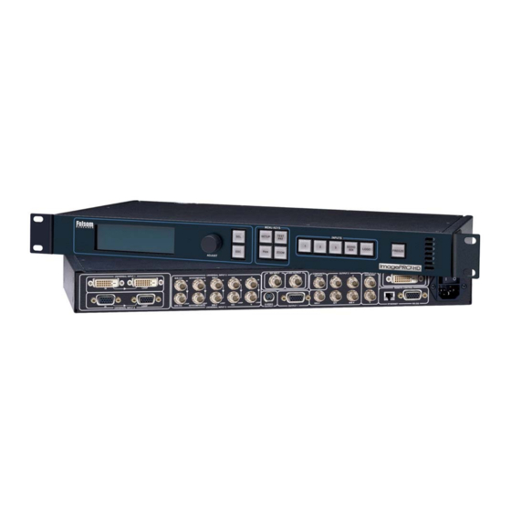
ImagePRO-SDI™ Rear Panel Connectors UNIVERSAL INPUT 1 R/R-Y/C G/Y/COMPOSITE LOOP LOOP LOOP R/R-Y/C G/Y/COMPOSITE UNIVERSAL INPUT 2 Figure 2-2: ImagePRO-SDI™ Rear Panel Video Input BNC connectors with loop-through (Universal input 3) Video Input HD-15 connectors with loop-through (Universal inputs 1 & 2) Standard Definition SDI Digital Video Input BNC Video Output BNC connectors (Output 2) Video Output HD-15 connectors (Output 1) -
Page 23: Imagepro-Hd™ Rear Panel Connectors
R/R-Y/C G/Y/COMPOSITE UNIVERSAL INPUT 2 Figure 2-3: ImagePRO-HD™ Rear Panel Video Input BNC connectors with loop-through (Universal input 3) Video Input HD-15 connectors with loop-through (Universal input 2) Digital / Analog Video Input on DVI-I Connector with loop-through (Universal input 1) -
Page 24: Rack-Mount Installation
Rack-Mount Installation ImagePRO units are designed to be rack mounted and are supplied with front rack-mount hardware. Rear rack- mount brackets are available as a kit and are recommended for use when units are mounted in transit cases. When rack mounting the unit, remember that the maximum ambient operating temperature for the unit is 40 degrees C. Leave at least one inch of space front and rear to make sure that the airflow through the fan and vent holes is not restricted. -
Page 25: Video Input Connections
YUV, S-Video (Y/C), or composite (NTSC, PAL or SECAM) video signals. On ImagePRO™ and ImagePRO-SDI™ Universal Inputs 1 & 2 are provided with HD-15 female connectors. On ImagePRO-HD™ Universal input 2 is provided with an HD-15 connector. Universal input 1 is provided with a DVI-I connector, which can be converted to an HD-15 via the DVI-I to HD-15 adaptor provided with the unit. -
Page 26: Video Output Connections
Video Output Connections Four independently buffered outputs (one five wire BNC connection, one HD-15, one S-Video, and one Composite video BNC) are provided. Both 5-wire and HD-15 outputs provide the same Video in RGB or YPbPr format. Outputs are available depending on the resolution selected. For example, RGB video at both on the 5-wire BNC and HD-15 outputs. - Page 27 RGB/YPbPr Video Output Connect the output device to the set of BNC connectors marked R/R-Y, G/Y and B/B-Y on the output section of the ImagePRO™ rear panel S-Video (Y/C) Video Output The Y/C video output connector is a 4-Pin Mini DIN located on the rear panel of the ImagePRO™. Using a commercial S-VHS cable, connect the Y/C video output to the input of the S-VHS device (monitor, video recorder, etc.).
-
Page 28: Dvi-I Video In And Loop-Through Connectors (Universal Input 1-Imagepro-Hd™)
DVI-I Video In and Loop-Through Connectors (Universal Input 1-ImagePro-HD™) Two DVI-I female connectors are located on the rear panel of the ImagePRO-HD™. One is used for Video input and the other one is used for the buffered DVI-I Loop-Through. This Connector can be used with Analog inputs using the DVI-I to HD-15 adaptor provided with ImagePRO-HD™. -
Page 29: Rs-232 Remote Control Connections
RS-232 Remote Control Connections The Remote serial port can be connected to a PC or other Remote Controller to support remote control of the ImagePRO unit. Pinouts for the remote port are shown below. DB-9 Refer to Section 3, SYSTEM: RS-232 Menu, for configuring the hardware handshake. Manual # 26-0302000-00 / Revision E RS-232 Signal Description... -
Page 30: Connection To Ac Power
Connection to AC Power Power Cord/Line Voltage Selection ImagePRO is rated to operate with the following supplies: Input Power: Power Consumption : The ImagePRO Wide Screen Image Processor performs line voltage selection automatically. No user controls are required for line voltage selection. When the ImagePRO 250 volts at 15 amps must be used. - Page 31 Connect ImagePRO to 115 VAC power using the power cord supplied with the unit. Locate the power switch on the power entry module at the rear of the unit and turn the power on. While the main board is initializing, “please wait” will be displayed and the front panel keys will be turned on and off.
- Page 32 Image PRO – Multi Format Image Processor Manual # 26-0302000-00 / Revision E...
-
Page 33: Chapter Three
CHAPTER THREE Operation What you will find in this chapter… Front Panel Controls Status Display Menu Control Setup Menus Input Setup Menu Output Setup Menu System Options Menu Test Pattern Menu Zoom Menu Pan Menu ImagePRO – Multi Format Image Processor Manual # 26-0302000-00 / Revision E Model IP-2003 ImagePRO –... - Page 34 ImagePRO – Multi Format Image Processor Manual # 26-0302000-00 / Revision E...
-
Page 35: Imagepro™ Front Panel Controls
Operation ImagePRO™ can be controlled by using the front panel menu controls or remotely via RS-232 or Ethernet interface. The front panel menu controls are described in detail in this section. Remote control commands are described in detail in section 4. ImagePRO™... -
Page 36: Imagepro-Sdi™ Front Panel Controls
ImagePRO-SDI™ Front Panel Controls Used to select a menu option, control setting, or configuration change. Current operation in progress is cancelled. Control returns to the previous menu or the system status display. Any changes made within a control function are undone. SETUP, TEST PAT, ZOOM, PAN These four buttons allow entry into the menu system. -
Page 37: Imagepro-Hd™ Front Panel Controls
To capture an image, the operator presses and holds the input source button to select the desired input source and then presses the Logo/Black button. ImagePRO-HD™ will freeze the output image and capture an output frame from the selected input source and store the image in non-volatile memory. A progress bar and related messages will be shown on the VFD display during this capture process to notify the operator that the image is being captured and saved. -
Page 38: Power Up Initialization
In addition to the twelve illuminated push buttons, the Front Panel controls also include a Vacuum Fluorescent Display (VFD) and an adjustment knob. The operation of each menu displayed on the VFD is described in detail in the following sections of this document. Power Up Initialization Locate the power switch on the rear panel and turn the ImagePRO following messages will be displayed on the VFD display:... - Page 39 For ImagePRO-SDI and ImagePRO-HD units, when there is a logo image stored in non-volatile memory, the logo will be loaded into memory at this time. During this loading process, the following message will be displayed on the VFD display: A progress bar will be displayed on the third line of the VFD display indicating the progress of loading the logo image.
-
Page 40: Status Display
Status Display After power-up or anytime none of the four menu buttons are selected, the display will show a basic status. This screen gives information about the currently selected system inputs and outputs. The input section always reflects the currently selected input channel, as determined by the input buttons. If the input channel is changed, then the input fields of this screen may change. - Page 41 The user can scroll through the menu items by turning the ADJUST control knob. A pointer (>) at the left of a menu item indicates the current position of the scroll bar. When the desired menu item is reached, the user presses the SEL key to select that menu item.
-
Page 42: Menu Operation
Menu Operation Setup This is the top-level menu accessed by pressing the SETUP button. Setup information can be stored in non-volatile memory within ImagePRO and will be automatically recalled each time the unit is turned on. The contents of this menu are: Input Setup Submenu This menu sets all the configuration options for the selected input channel. -
Page 43: Type Selection
When Auto Acquire is on the type selections will be limited depending on the signal on the currently selected input channel. For example, if channel 1 of an ImagePRO-HD™ is connected to a DVI source, DVI will be the only choice and it could not be changed. -
Page 44: Sampling
The Color space value allows the user to select among the possible Component Video Standards for YPbPr. For all other video types the color space is RGB and cannot be selected or changed. The default selection for YPbPr is SMPTE. The user may change this setting to BETA or M-II to allow the ImagePRO™ to correctly sample the Y, Pb and Pr components across their full dynamic range. -
Page 45: 1:1 Sampling Overview
1:1 Sampling Overview In order to scale an image it must first be digitized. This is the process of changing the analog graphics signals (Red, Green, and Blue for example) into pixels stored in the ImagePRO ImagePRO is to over sample the input image producing more samples than there are in the original source material. -
Page 46: Contrast And Brightness
raster box is intentionally “broken” to allow the user to view the input video behind it and align the input video to the raster box precisely. Contrast And Brightness The adjustment range is 75.0% to 125.0%. 100% is the default setting for both contrast and brightness. The Contrast and Brightness controls allow the operator to adjust the overall contrast and brightness of the image. -
Page 47: Letterbox Selection
This menu allows the user to set the input signal aspect ratio. The menu is: The Mode value is selected among the following choices: 1:1, 3:2, 4:3, 5:4, 16:9, Custom The ImagePRO will select and display the input video aspect ratio according to the input format detected. For example, computer video at 1280x1024@60Hz ratio, and HDTV1080i video will default to 16:9 aspect ratio. -
Page 48: De-Interlacing
Video Processing Delay for ImagePRO-SDI and ImagePRO-HD ImagePRO-SDI and ImagePRO-HD utilize an advance MAD processor capable of processing interlaced inputs up to HDTV (1920 x 1080i) rates. When the MAD de-interlacing mode is selected, maximum video processing delay is 2 input fields (3 fields if output not frame locked to input). -
Page 49: Reset Config
NOTE: Configuration parameters entered in the input setup menu are saved in non-volatile memory for each input source by using the SAVE CONFIG menu item. If the SAVE CONFIG menu item is not selected, the information will not be restored upon the next system power up sequence. A filename may include up to 19 characters. -
Page 50: Recall Config
Recall Config This menu allows the user to recall input configurations that were previously saved for the currently selected input format and type. Only configurations that match the current format and type will be displayed. In order to recall a configuration, press SEL. -
Page 51: Output Setup Submenu
Note that the unit’s outputs are not updated until the SEL button is pressed. NOTE: The Digital Cinema Projector resolutions at supported on the ImagePRO-SDI and ImagePRO-HD. Timing Adjust Submenu The Timing Adjust sub-menu allows the user to make adjustments to the currently selected output format timing parameters. -
Page 52: Comp/S-Vid Adjustments Submenu
For the Horizontal entries, the unit of measure is pixels. H Total indicates the total pixel count per line. H Position sets the offset of start of active area from H sync. H Active sets the size of the active area. H Sync sets the H sync width. For the vertical entries, the unit of measure is lines. -
Page 53: Sync Settings Submenu
Sync Settings Submenu This menu allows the user to specify the sync types for the current output. The submenu is illustrated below: The Sync Out menu item selects among the five possible output sync types: CSync, +H+V, +H-V, -H+V, -H-V. The default setting is -H-V for most formats. For NTSC, PAL, RS-170 and RS-343 the default is Csync with equalizations on. -
Page 54: Flicker Reduce
Flicker Reduce The Flicker Reduce value is n/a when the output format is non-interlaced. For interlaced formats, the range is Off (no flicker reduction) or +1 (minimum flicker reduction) through +20 (maximum flicker reduction). Genlock Submenu This sub-menu sets up the genlock operation: Source Source selects the genlock source from among the following: Freerun... -
Page 55: H Phase
With ImagePRO-SDI or ImagePRO-HD units, when Genlock type HV is selected, and the ImagePRO output is interlaced, the message “FOR SDI OUT” is displayed as shown below: H Phase The H Phase setting allows the output H timing to be adjusted relative to the genlock source. This selection is n/a when the genlock is V lock only. - Page 56 When Input Auto Acquire is On, the system will always perform a full sync acquisition on the input signal anytime the input channel is selected, the input type is changed, or the input signal changes sync rates. When Auto Acquire is Off, the system will use the last known configuration for each input channel, to the greatest extent possible.
-
Page 57: Formats Submenu
Formats Submenu This menu is used to define and save a new video format, or to edit and save a previously-defined format. These saved formats are stored in a user library, which is searched during the auto-acquisition process before the standard system library. All saved formats are available as input formats on any input channel and as output formats. - Page 58 The <editable_string> field can be selected with the SEL button. The content of the field will initially be “Format1”. Editing the string is initiated by pressing SEL with the > cursor on the editable line. At this point, the > changes to #, and a cursor will appear at the first character position of the string.
-
Page 59: Delete Submenu
If the user picks a name that's already in use in the user library, a confirmation menu is displayed when the user invokes the Save command: Pressing the SEL key will cause the existing library format to be overwritten with the new format. Pressing the ESC key will cancel the save operation and return to the previous menu. -
Page 60: H,V Parameters
If the format selected for deletion is currently an Input format used by any of the input channels or is the Input format that is saved in an input configuration, the following screen will be displayed: H,V Parameters These selections set the H and V parameters (Total, Active, Front Porch, and Sync Width). The units are in pixels for H and lines for V. -
Page 61: Views Submenu
Views Submenu The Views menu allows management of up to 16 stored “Views”. A View is a combination of zoom and pan settings. For example, the user may define a view that maps the entire input image to the upper left quarter of the output image. - Page 62 The view to delete is selected from the list of available views. Deleting a view simply resets its pan and zoom settings to their default values. A confirmation screen will appear when SEL is pressed. ImagePRO – Multi Format Image Processor DELETE VIEW >...
-
Page 63: Effects Submenu
- Transition with Logo; (ImagePRO-SDI & ImagePRO-HD only). This mode is only selectable if there is stored Logo image in non-volatile memory. The currently selected channel will dissolve to the stored Logo image and then the new channel’s video will dissolve in from the Logo. -
Page 64: Tech Support Submenu
Tech Support Submenu The version displayed is the installed operating firmware version number. ImagePRO – Multi Format Image Processor TECH SUPPORT Version <fw_ver> Phone 866-FRI-SUPT Manual # 26-0302000-00 / Revision E... -
Page 65: System Submenu
System Submenu This menu allows the user to adjust the VFD Brightness and remote control setting for RS-232 or Ethernet Interfaces as illustrated below. NOTE: Configuration parameters entered in the system menu are saved in non-volatile memory by using the SAVE SYSTEM STATE menu item. -
Page 66: Ethernet Submenu
The handshake value is selected from the following values: Off or On (CTS/RTS). The reset command restores the RS232 settings to defaults: 38400, N81, Handshake On. After connecting the PC COM port to the ImagePRO RS-232 connector the user may open a serial terminal session (Hyper-terminal, Procomm etc) and configure it to match the ImagePRO serial port settings as they are configured in this menu. - Page 67 SET IP Valid "nnn" fields can range from 000 to 255. As with any selection line, the user must press the SEL button to begin editing the IP values. At this point, the first value is highlighted. Turning the knob moves the value through the range 0 to 9.
-
Page 68: Edid Dvi Input Format Submenu
ImagePRO-HD™ EDID file is stored in a non-volatile memory. This file is read by a computer’s DVI graphic card when the DVI output is connected to ImagePRO-HD™’s channel 1 DVI-I input connector during boot-up. ImagePRO must be powered on first for the EDID information to be read. - Page 69 ERROR! DVI INPUT AND LOOP THRU CONNS MUST BE DISCONNECTED! <ESC> = Continue Press the ESC key to proceed with the non-volatile memory programming. Once no DVI source or display Device are detected, ImagePRO will proceed with programming the non-volatile memory while the following message is briefly displayed.
-
Page 70: Save System State
Save System State This command explicitly saves all settings in the system state submenu so they may be restored at power up. This command will also save the currently selected input channel as the default input selection upon power up. If the user wants the ImagePRO to always power up and acquire and convert an input other than input one, the user must perform a save system state command while the desired input is selected. -
Page 71: Test Pattern Menu
Test Pattern Menu This menu is invoked by pressing the TEST PAT button. The type selection enables a test pattern or turns them off. The value choices are: H Ramp V Ramp 100% Col Bars 75% Col bars 16x16 Grid 32x32 Grid Burst 50% Gray... -
Page 72: Zoom Menu
Zoom Menu This menu is invoked by pressing the ZOOM button. The default zoom amount is 100%. By selecting Amount and pressing SEL the user may increase zoom above 100% (zoom into the input Video) or decrease zoom below 100% (zoom out). - Page 73 Manual # 26-0302000-00 / Revision E ImagePRO – Multi Format Image Processor...
-
Page 75: Chapter Four
CHAPTER FOUR Remote Commands What you will find in this chapter… Serial Command Syntax Remote Commands ImagePRO ImagePRO – Multi Format Image Processor Manual # 26-0302000-00 / Revision E Command List/Description Model IP-2003 ImagePRO – Multi Format Image Processor... - Page 76 ImagePRO – Multi Format Image Processor Manual # 26-0302000-00 / Revision E...
-
Page 77: Serial Command Syntax
Serial Command Syntax Serial Parameters The following are the default parameter settings for serial communication. Baud Rate is 38.4K. Parity is NONE. Stop Bit is 1. Data Bit is 8. For RS-232 signal connections, refer to Chapter 2 – Installation. RS232 Mode The ImagePRO will respond with a '#' prompt when the command processor is ready for a command. -
Page 78: Imagepro Remote Commands
ImagePRO Remote Commands Resolution Remote Commands RESH RESI nn RESI? RESO nn RESO? Input Remote Commands ACQ mode ACQ? DINT in mode DINT? in PCOMP in mode PCOMP? in FREEZ mode FREEZ? IAR in n cn IAR? in IAUTOC IBRT in nnn.n IBRT? in ICNT in nnn.n ICNT? in... - Page 79 ISMP? in ISYNC in mode ISYNC? in ISYNCSLICE in nnn ISYNCSLICE? in ITYPE in mode ITYPE? in IVATV nnnn IVATV? IVPOS nnnn IVPOS? IVTOTAL? IVREC in IVSAV in LCK? in RTE in RTE? Output Remote Commands GLMODE src type GLMODE? GLPHASE h sc GLPHASE? OBRT nnn.n...
- Page 80 OUSCN? OTPM type raster OTPM? OVATV nnnn OVATV? OVPOS nnnn OVPOS? OVSYNC nnnn OVSYNC? OVTOTAL nnnn OVTOTAL? Edit Custom Format Remote Commands EFLIST EFRES nn EFRES? EFRESH EFHTOTAL nnnn EFHTOTAL? EFHATV nnnn EFHATV? EFHFP nn EFHFP? EFHSYNC nn EFHSYNC? EFHRATE? EFVTOTAL nnnn EFVTOTAL? EFVATV nnnn...
- Page 81 Logo Remote Commands LOGOD LOGOL LOGOS LOGOI Effects Related Commands TRN type n TRN? Pan / Zoom / View Remote Commands PANH nnn.n PANH? PANHV hhh.h vvv.v PANHV? PANV nnn.n PANV? VIEW? nn VIEWD nn VIEWR nn VIEWS nn VIEWI? in VIEWIR VIEWIS in ZOOM nnn.n...
-
Page 82: Imagepro Tm Command List/Description
ImagePRO Command List/Description Resolution Remote Commands Command: RESH Description: Query the available resolution list for the ImagePRO. Parameters: None Returns: All available resolutions in the format: n : HxV @F (example: 20 : 1024x768 @59.94) Example: RESH (Query all available resolutions) Command: RESI nn Description:... -
Page 83: Input Remote Commands
DINT in mode Description: Sets De-interlacer mode. Motion de-interlacer mode is only available for Interlaced inputs Parameters: in - Input chnl (1-4) chnl 4 only for ImagePRO-SDI and ImagePRO-HD units mode - De-interlacer mode [0-1] Motion | Fld->Frm Query DINT? in... - Page 84 n - Input Aspect Ratio: n[0-5], 1:1 | 3:2 | 4:3 | 5:4 | 16:9 | Custom cn - (Optional) Custom Input Aspect Ratio: (0.75 – 3.00) NOTE: cn parameter is not required unless user selects Custom Input Aspect Ratio (i.e. n = 5) Query: IAR? in Returns the Input Aspect Ratio of specified source in the format...
- Page 85 Description: Recalls saved Input Configuration. Parameters: in - Input chnl (1-4) chnl 4 only for ImagePRO-SDI and ImagePRO-HD units filename – configuration that is being recalled (not case sensitive). Example: ICREC 3 file1 (Recalls Input configuration stored as file1 for channel 3.)
- Page 86 Set Input Edge in oversample mode. The minimum and maximum limit is dependent on the input resolution. Parameters: in - Input chnl (1-4) chnl 4 only for ImagePRO-SDI and ImagePRO-HD units edge (L|R|T|B) nnnn - Input edge: nnnn if edge=L [Input H Sync-( Input H Sync + (Input H total X 0.25))] if edge=R [((H Total –...
- Page 87 Set Input Horizontal Total. The minimum and maximum limit is dependent on the input resolution. Parameters: in - Input chnl (1-4) chnl 4 only for ImagePRO-SDI and ImagePRO-HD units nnnn - Input Horizontal Total: nnnn[(Actual Input H Total * 2/5) - +(Actual Input H Total * 9/5)]...
- Page 88 ISAT in nnn Description: Adjust Input Saturation. Parameters: in - Input chnl (1-4) chnl 4 only for ImagePRO-SDI and ImagePRO-HD units nnn - Input Saturation (75 – 125 if input is YPbPr, 0 – 150 otherwise) Query: ISAT? in Returns the Input Saturation in the format...
- Page 89 Parameters: in - Input chnl [1-3] mode - Mode [0|1|2|3], RGB | YPbPr | NTSC/PAL/SECAM | DVI (DVI available only on chnl 1 for ImagePRO-SDI and ImagePRO-HD units) Query: ITYPE? in Returns the Input Type selected for the specified input channel in the format...
- Page 90 IVTOTAL? (Queries Input Vertical Total) Command: IVREC in Description: Input Channel View Recall. Parameters: in - Input chnl (1-4) chnl 4 only for ImagePRO-SDI and ImagePRO-HD units Example: IVREC 1 (Recalls Input Channel View of channel 1) Command: IVSAV in Description: Input Channel View Save.
- Page 91 Output Remote Commands Command: GLMODE src type Description: Sets Genlock Source and Genlock Type Parameters: src [0-4], Freerun | Input Video | H+V Sync | C Sync | Black Burst type [1-3], V Lock | HV Lock | HVScLock(Full lock) Query: GLMODE? Returns the Genlock Source and Genlock Type in the format...
- Page 92 Parameters: None Example: OCRST (Reset Output Configuration) Command: OCSAV Description: Save Output Configuration to non-volatile memory. Parameters: None Example: OCSAV (Save Output Configuration) Command: OCSP mode Description: Sets Output Colorspace mode. Parameters: mode - [0-1] RGB | YPbPr Query: OCSP? Returns the Output Colorspace mode in the format = mode Example:...
- Page 93 Command: OHATV nnnn Description: Set Output Horizontal Active. The minimum and maximum limit is dependent on the output resolution. Parameters: nnnn - Output Horizontal Active: nnnn[ (Actual Output H Active * 2/10, with absolute minimum value of 150) - +(Actual Output H Active * 6/5, with absolute maximum of Output H Total – Output H Sync)] Query: OHATV?
- Page 94 Command: OHUE nnn Description: Adjust Output Hue. Only applicable if output is NTSC. n/a if PAL Parameters: nnn - Output Hue (-22.0 - +22.0) Query: OHUE? Returns the Output Hue value in the format = nnn Example: OHUE 20 (Adjust Output Hue to 20) OHUE? (Queries Output Hue) Command:...
- Page 95 OSHRP? (Queries Output Sharpness) Command: OSOG n Description: Output Sync On Green mode. Parameters: n - Output SOG: n[0-2] Off | Standard | Tri-level Query: OSOG? Returns the Output Sync On Green mode in the format Example: OSOG 0 (Turns off Output Sync On Green mode) OSOG? (Queries Output Sync On Green mode) Command: OSYNC n...
- Page 96 of 150) - +(Actual Output V Active *6/5, with absolute maximum value of Output V Total – Output V Sync)] Query: OVATV? Returns the Output Vertical Active value in the format = nnnn Example: OVATV 768 (Set Output Vertical Active to 768) OVATV? (Queries Output Vertical Active) Command:...
- Page 97 Edit Custom Format Remote Commands Command: EFLIST Description: Lists the names of all saved custom formats. Parameters: None Returns: List the names of saved custom formats, one name per line. Example: EFLIST (Lists all saved custom formats.) Command: EFRES nn Description: Set base resolution for custom formats.
- Page 98 Command: EFHATV nnnn Description: Set custom format’s Horizontal Active value. Parameters: nnnn - H Active [500 - +(H Total - H Sync - H Front Porch)] Query: EFHATV? Returns the custom format’s Horizontal Active value in the format = nnnn Example: EFHATV 1024 (Set custom format H Active as 1024) EFHATV?
- Page 99 Command: EFVATV nnnn Description: Set custom format’s Vertical Active value. Parameters: nnnn - V Active [400 - +( V Total - V Sync - V Front Porch)] Query: EFVATV? Returns the custom format’s Vertical Active value in the format = nnnn Example: EFVATV 768 (Set custom format V Active as 768) EFVATV?
- Page 100 EFDEL filename Description: Deletes saved custom format. This filename is translated to all upper case characters Parameters: filename – name of custom format to be deleted (translated to upper case). Example: EFDEL FORMAT1 (Deletes custom format with the name “FORMAT1”.) ImagePRO –...
-
Page 101: System And Ethernet Remote Commands
System and Ethernet Remote Commands Command: DMSG mode Description: Sets Debug message display mode. Parameters: mode - DMSG mode [0-1] Off | On Query: DMSG? Returns the Debug message display mode in the format = mode Example: DMSG 1 (Sets Debug message mode to On) DMSG? (Queries the DMSG mode) Command: EDHCP mode... - Page 102 Example: EMAC? (Queries for Ethernet MAC address) Command: SBAUD n Description: Adjust the Serial Baud Rate. Parameters: n - Serial baud rate: n[0-4] 1200 | 2400 | 9600 | 19200 | 38400 Query: SBAUD? Returns the Serial Baud Rate in the format Example: SBAUD 0 (Adjusts Serial Baud Rate to 1200) SBAUD? (Queries Serial Baud Rate.)
- Page 103 Logo Remote Commands Command: LOGOD Description: Delete Logo image from non-volatile memory. Selecting Black/Logo channel will now display black. Logo feature only available on ImagePRO-SDI and ImagePRO-HD. Parameters: None Example: LOGOD (Delete saved Logo image.) Command: LOGOL Description: Load current output image from non-volatile memory as Logo image. Logo feature only available on ImagePRO-SDI and ImagePRO-HD.
- Page 104 Selects transition type when switching between inputs. Transition delay is only applicable if the transition type selected is Fade to black / Fade to logo. Fade to logo transition type only available on ImagePRO-SDI and ImagePRO-HD units, and is only selectable if Logo has been stored in non- volatile memory.
- Page 105 Pan / Zoom / View Remote Commands Command: PANH nnn.n Description: Set Output Horizontal Pan. Parameters: nnn.n - Horizontal Pan (-100.0% - +100.0%) Query: PANH? Returns the Output Horizontal Pan value in the format = nnn.n Example: PANH 50(Set Output Horizontal Pan to 50%) PANH? (Queries Output Horizontal Pan) Command: PANHV hhh.h vvv.v...
- Page 106 Description: Query saved Input channel View settings (i.e. Zoom setting, Pan H setting, Pan V setting) Parameters: in - Input chnl (1-4) chnl 4 only for ImagePRO-SDI and ImagePRO-HD units Returns: nnn.n - Zoom value [min-max] depends on scale factor hhh.h - Horizontal Pan (-100.0% - +100.0%)
- Page 107 Manual # 26-0302000-00 / Revision E ImagePRO – Multi Format Image Processor...
-
Page 109: Chapter Five
CHAPTER FIVE Software Upgrade Instructions What you will find in this chapter… Software Upgrade Instructions ImagePRO – Multi Format Image Processor Manual # 26-0302000-00 / Revision E Model IP-2003 ImagePRO – Multi Format Image Processor... - Page 110 ImagePRO – Multi Format Image Processor Manual # 26-0302000-00 / Revision E...
-
Page 111: Overview
Software Upgrade Instructions Overview The ImagePRO units incorporate the system software in a Flash memory component. Flash memory allows easy field upgrades without the need to send the unit back to the factory. The loader utility provides the capability to update the system Flash module with the latest revision of software. The upgrade utility can be run from a hard drive (recommended) or a floppy drive. -
Page 112: Preparing To Upgrade The Imagepro Unit
Find the Folsom Research folder and select ImagePRO Flash File Loader. Preparing to Upgrade the ImagePRO Unit Plug the DB-9 male connector into the port labeled “RS-232 on the back of the ImagePRO unit. Make sure the other end of the cable is attached to the available COM port on the back of the computer performing the upgrade. -
Page 113: Chapter Six
CHAPTER SIX Barco Folsom Information What you will find in this chapter… Warranty RMA Information Technical Support/General Contact Information ImagePRO – Multi Format Image Processor Manual # 26-0302000-00 / Revision E Model IP-2003 ImagePRO – Multi Format Image Processor... - Page 114 ImagePRO – Multi Format Image Processor Manual # 26-0302000-00 / Revision E...
-
Page 115: Barco Folsom Warranty
(drop/crush), and/or other unusual damages. The customer shall pay shipping charges when unit is returned for repair. Barco Folsom will cover shipping charges for return shipments to customers. - Page 116 ImagePRO – Multi Format Image Processor Manual # 26-0302000-00 / Revision E...
-
Page 117: Appendix
APPENDIX Technical Specifications Model IP-2003 ImagePRO – Multi Format Image Processor Manual # 26-0302000-00 / Revision E ImagePRO – Multi Format Image Processor... - Page 118 ImagePRO – Multi Format Image Processor Manual # 26-0302000-00 / Revision E...
-
Page 119: Technical Specifications
Connectors: Input 1 and 2 on 15-pin HD connectors with buffered loop-through. Input 3 on five BNC connectors with buffered loop-through. On ImagePRO-HD input 1 on DVI-I connectors. Serial Digital Video Input: (1) SDI input on ImagePRO-SDI model, or SDI/HDSDI input on ImagePRO-HD Connectors: BNC... - Page 120 User Control Local: User-friendly front panel interface Ethernet connection (with TCP/IP) or RS-232 serial port for real-time control Physical Height: 1.5"; Width: 17" (43.2 cm) or 19" (48.3 cm) with rack-mount option; Depth: 13"; Weight: 9lbs. ; Shipping Weight: 13 lbs. Input Power 100-240 VAC, 47-63 Hz Environmental...
- Page 121 FCC Classification This equipment has been tested and found to comply with the limits for a Class A digital device, pursuant to Part 15 of the FCC Rules. These limits are designed to provide reasonable protection against harmful interference when the equipment is operated in a commercial environment. This equipment generates, uses, and can radiate radio frequency energy and, if not installed and used in accordance with the instruction manual, may cause harmful interference to radio communications.
Need help?
Do you have a question about the ImagePRO-SDI and is the answer not in the manual?
Questions and answers