Table of Contents
Advertisement
Quick Links
Advertisement
Table of Contents

Related Manuals for Barco LED-PRO


Summary of Contents for Barco LED-PRO
- Page 1 ibaJmol rëÉêÛë=dìáÇÉ • Manual # 26-0501000-00 • Revision B...
- Page 2 30 days after the transfer of risks. In the event of justified notice of compliant, Barco can repair the fault or provide a replacement at its own discretion within an appropriate period. If this measure proves to be impossible or unsuccessful, the purchaser can demand a reduction in the purchase price or cancellation of the contract.
- Page 3 Not included in the guarantee coverage are system failures which are attributed to programs or special electronic circuitry provided by the purchaser, e.g. interfaces. Normal wear as well as normal maintenance are not subject to the guarantee provided by Barco either.
- Page 4 To avoid fire hazard, use only the fuse having identical type, voltage rating, and current rating characteristics. Refer fuse replacement to qualified service personnel. aç=kçí=léÉê~íÉ=áå=bñéäçëáîÉ=^íãçëéÜÉêÉë To avoid explosion, do not operate this product in an explosive atmosphere. LED-PRO • User’s Guide...
- Page 5 Ein Ausrufungszeichen innerhalb eines gleichwinkeligen Dreiecks dient dazu, den Benutzer auf wichtige Bedienungs-und Wartungsanweisungen in der Dem Great beiliegenden Literatur aufmerksam zu machen. LED-PRO • User’s Guide...
- Page 6 `Ü~åÖÉ=eáëíçêó The table below lists the changes to the LED-PRO User’s Guide. Table 0-1. Change History Date ECO # Description Approved By 8/1/05 1478 Release Jim Wickenhiser 5/1/06 1620 Change summary: Jim Wickenhiser • Added new features including Setup Wizard, Input Wizard, diagonal test pattern scrolling and 50/60Hz refresh rate selection.
-
Page 7: Table Of Contents
LED-PRO Front Panel ........ - Page 8 Input ......... . . 68 viii LED-PRO • User’s Guide...
- Page 9 Pan & Zoom Menu Tree ........95 LED-PRO • User’s Guide...
- Page 10 Tile Count ....... 101 LED-PRO ID ......101 LED Wall ID .
- Page 11 RS-232 Mode ..........127 LED-PRO Remote Commands........128 Resolution Remote Commands.
- Page 12 EFVATV nnnn ........152 LED-PRO • User’s Guide...
- Page 13 Contact Information ......... . . 162 fåÇÉñ =K=K=K=K=K=K=K=K=K=K=K=K=K=K=K=K=K=K=K=K=K=K=K=K=K=K=K=K=K=K=K=K=K=K=K=K=K=K=K=K=K=K=K=K=K=K=K=K=K=K=K=KNSP LED-PRO • User’s Guide xiii...
- Page 14 Table of Contents LED-PRO • User’s Guide...
-
Page 15: Chapter Structure
NK==fåíêçÇìÅíáçå få=qÜáë=`Ü~éíÉê This chapter is designed to introduce you to the LED-PRO™ User’s Guide. Areas to be covered are: • Chapter Structure • How to Use This Guide • Conventions • About the LED-PRO • Features • What’s New in Firmware Version 2.0 •... - Page 16 NK==fåíêçÇìÅíáçå Chapter Structure `Ü~éíÉê=píêìÅíìêÉ The following chapters provide instructions for all aspects of LED-PRO operations: • Chapter 1, “Introduction” provides a system overview, a list of features, and a system connectivity diagram. • Chapter 2, “Hardware Orientation” on page 9 provides detailed diagrams of the system’s front and rear panels.
- Page 17 ... indicates the following sequence: Press SETUP to display the Setup Menu. Scroll to the Expert Mode line and press SEL to display the Expert Mode Menu. Scroll to the System line and press SEL to display the System Menu. LED-PRO • User’s Guide...
- Page 18 About the LED-PRO ^Äçìí=íÜÉ=ibaJmol The LED-PRO is a powerful all-in-one signal processor that accepts a wide range of video input signals, and processes them to drive Barco LED displays. The LED-PRO allows you to scale visual sources and mix them in multiple ways while still maintaining superb picture quality.
-
Page 19: Features
Analog” section on page 43 for details. Additional sections are provided for SDI and DVI sources. • Expert Mode This mode gives experienced LED-PRO users the ability to perform more in-depth alignments. In Chapter 4, refer to the “Using the Expert Mode Menu” section on page 66 for details. - Page 20 (version 1.03.01) to ensure proper LED-PRO operation. The patch is located on the Barco website, at the following location: Link: Director Toolset Patch Scroll down to the LED-PRO section and follow the directions to install the patch. LED-PRO • User’s Guide...
-
Page 21: Connectivity Diagram
The maximum of four inputs are shown, one each in RGB, DVI, Composite and HD-SDI formats. • Two different paths from LED-PRO to the LED wall are shown: Via DVI, direct between the LED-PRO and the wall. Via DVI and fiber optics, via the optional Barco Fiberlink Transmitter and Receiver. -
Page 22: Application Questions
Application Questions ^ééäáÅ~íáçå=nìÉëíáçåë At Barco, we take pride in offering unique solutions to demanding technical problems. If you have application questions, require further information or would like to discuss your application requirements in more detail, please call (916) 859-2500. Our Customer Support Engineers will be happy to supply you with the support you need. -
Page 23: Led-Pro Front Panel
OK==e~êÇï~êÉ=lêáÉåí~íáçå få=qÜáë=`Ü~éíÉê This chapter provides detailed diagrams of the system’s front and rear panels. The following topics are discussed: • LED-PRO Front Panel • LED-PRO Rear Panel LED-PRO • User’s Guide... -
Page 24: Display Section
2. Hardware Orientation LED-PRO Front Panel ibaJmol=cêçåí=m~åÉä The figure below illustrates the LED-PRO front panel: MENU KEYS Visibly yours INPUTS TEST SETUP 1024x768@59.94 INPUT SD/HD LOGO OUT: Freerun PAN & Wall: Enabled ZOOM ADJUST LED-PRO Figure 2-1. LED-PRO Front Panel... - Page 25 • The Menu Display is a 4 line x 20 character Vacuum Fluorescent Display (VFD) that shows all LED-PRO menus and sub-menus. Brightness is adjustable. S E T U P > S e t u p W i z a r d >>...
- Page 26 Menu Keys Section takes you directly to the selected menu. • If you have made a change within a particular menu and you press one of the five buttons in the Menu Keys Section, you will be prompted to save your changes. LED-PRO • User’s Guide...
-
Page 27: About The Logo
LOGO — selects the LOGO (as stored in flash memory) as the LED wall’s source. When pressed, the LOGO is routed to the output using the transition type LOGO specified in the Effects Menu. Refer to the “About the LOGO” section on page 14 for additional details. LED-PRO • User’s Guide... - Page 28 If you perform a factory reset, the LOGO is cleared from flash memory. • You can delete the LOGO manually from flash memory using the Logo Menu. In Chapter 4, refer to the “Logo” section on page 86 for menu details. LED-PRO • User’s Guide...
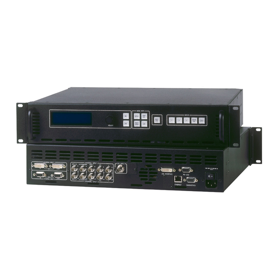
- Page 29 2. Hardware Orientation LED-PRO Rear Panel ibaJmol=oÉ~ê=m~åÉä The figure below illustrates the LED-PRO rear panel: SDI INPUT UNIVERSAL INPUT 3 UNIVERSAL INPUT 1 100-240 V 50-60 Hz R/R-Y/C G/Y/COMPOSITE B/B-Y 2.3 A LOOP LED INTERFACE RS-232 LOOP LOOP LOOP LOOP...
-
Page 30: Led-Pro Rear Panel
In Appendix A, refer to the “Serial and Diagnostic Connector” section on page 124 for pinouts. AC Connector One AC Connector is provided for connecting LED-PRO to your facility’s AC power source. The integral switch turns the chassis on and off. LED-PRO • User’s Guide... -
Page 31: Safety Precautions
PK==fåëí~ää~íáçå få=qÜáë=`Ü~éíÉê This chapter provides detailed instructions for installing the LED-PRO hardware. The following topics are discussed: • Safety Precautions • Unpacking and Inspection • Site Preparation • Cable and Adapter Information • Rack-Mount Installation • Power Installation • Signal Installation •... - Page 32 Before opening the LED-PRO box, inspect it for damage. If you find any damage, notify the shipping carrier immediately for all claims adjustments. As you open the box, compare its contents against the packing slip. If you find any shortages, contact your Barco sales representative.
- Page 33 3. Installation Rack-Mount Installation o~ÅâJjçìåí=fåëí~ää~íáçå LED-PRO units are designed to be rack mounted and are supplied with front rack-mount hardware. Please note the following important points: • Rear rack-mount brackets are available as a kit, and are recommended for use when units are mounted in transit cases.
-
Page 34: Power Installation
Input Power: 100-240 VAC, 47-63 Hz • Power Consumption: 150 watts maximum LED-PRO performs line voltage selection automatically, and no user controls are required. The AC power cords must be accessible so that they can be removed during field servicing. Warning... -
Page 35: Signal Installation
3. Installation Signal Installation páÖå~ä=fåëí~ää~íáçå The figure below illustrates a sample LED-PRO system diagram. Use this figure for reference during the signal installation process. (Optional) Fiberlink Receiver (Optional) Fiberlink Transmitter Fiber Optics Up to 4 Inputs Camera (Composite) LED Wall... - Page 36 — in the proper sequence. Refer to your specific LED tile’s “User’s Guide” for details. Connect LED-PRO’s LED Interface output to the data input of your LED wall. Please note: Use the proper cable, depending upon your LED wall’s input connector (e.g., DVI or MDR).
-
Page 37: Format Connection Table
3. Installation Format Connection Table cçêã~í=`çååÉÅíáçå=q~ÄäÉ Use the following table to connect various source formats to LED-PRO, using the system’s universal input connectors in conjunction with a customer supplied VGA to 5 x BNC breakout cable. Please note: • RGB format — typical devices: Computers •... - Page 38 3. Installation Format Connection Table LED-PRO • User’s Guide...
-
Page 39: Control Overview
QK==léÉê~íáçå få=qÜáë=`Ü~éíÉê This chapter provides comprehensive menu descriptions and detailed operating instructions for the LED-PRO. The following topics are discussed: • Control Overview • Power-Up Initialization • Quick Setup and Operations • Menu Tree • Using the Menu System •... -
Page 40: Standard Bootup
Toolset User’s Guide” for more information. mçïÉêJré=fåáíá~äáò~íáçå After connecting power to the LED-PRO, locate the power switch on the back of the chassis, and turn the power ON. The LED button lights, and the display shows a series of initialization screens. The screens vary depending upon the last state of the system: •... - Page 41 • If DHCP was enabled, LED-PRO will attempt to contact the DHCP server for an IP address. During this process, the following message is shown: S e a r c h in g f o r D H C P s e r ve r Please wait ...
- Page 42 At the conclusion of the boot-up procedure, the Input 1 button will light and the Status Menu is shown. Note By default, LED-PRO boots up with Input 1 selected from a “factory reset” operation. However, if you perform the “Save System State” procedure with a different input selected, the system will acquire and select that input.
-
Page 43: Quick Setup And Operations
Reference” section on page 33, and select the function that you wish to perform. • For a complete overview of all system operating procedures, start with the “Menu Tree” section on page 30 and review the entire chapter. LED-PRO • User’s Guide... -
Page 44: Menu Tree
4. Operation Menu Tree jÉåì=qêÉÉ The figure below illustrates a simplified view of the LED-PRO Menu Tree. Use this diagram for reference throughout this chapter. Please note: • In the diagram, only “top level” menus are shown. • The symbol >>... - Page 45 4. Operation Using the Menu System rëáåÖ=íÜÉ=jÉåì=póëíÉã This section lists the rules and conventions for using LED-PRO’s menu system. The figure below illustrates a sample menu: T E S T P A T T E R N T yp e Bu rst >...
- Page 46 The display itself is four lines high, and the ADJUST knob is used to scroll through the various menu lines. Throughout this chapter, entire menus will be shown for clarity — rather than a series of four-line sections. LED-PRO • User’s Guide...
-
Page 47: Quick Function Reference
Quick Function Reference nìáÅâ=cìåÅíáçå=oÉÑÉêÉåÅÉ Use the following table to quickly access the proper menu for a specific function. Both hyperlinks and page numbers are provided. Table 4-1. LED-PRO Quick Function Reference Table How to: Use the Following: Page Adjust 1:1 timing... - Page 48 4. Operation Quick Function Reference Table 4-1. LED-PRO Quick Function Reference Table (Continued) How to: Use the Following: Page Enable or disable the LED boost mode Boost Mode Enable or disable the LED creative mode Creative Mode Enable or disable the LED OSD (on screen display)
- Page 49 4. Operation Quick Function Reference Table 4-1. LED-PRO Quick Function Reference Table (Continued) How to: Use the Following: Page Set LED wall control to local or remote LED Control Set minimum delay Minimum Delay Set the display mode to crop or scale Display Mode Set the input’s aspect ratio...
-
Page 50: Using The Status Menu
ESC twice to access the Status Menu. • Toggle a selected menu button off — from any level down the menu tree. You are several levels down the Setup Menu. Press SETUP to access the Status Menu directly. LED-PRO • User’s Guide... - Page 51 V Lock, Input — vertical lock to input video If the unit is set for a particular “Lock to Source” mode and type, but that source is missing (or lock can not be achieved), the unit periodically attempts to lock. While LED-PRO • User’s Guide...
- Page 52 Wall: Enabled — Barco LED wall detected and enabled Wall: Standby — Barco LED wall detected and in standby mode If no wall is detected, ensure that the Barco LED Wall is properly connected to the LED-PRO connector labeled "LED Interface."...
-
Page 53: Using The Setup Menu
The following topics are discussed in this section: • Setup Menu Tree • Setup Menu Description • Programming EDID • Using the Setup Wizard • Using the Input Wizard • Using the Expert Mode Menu LED-PRO • User’s Guide... - Page 54 EDID Format Presets Recall Save Delete RS-232 RS-232 Expert Mode Input >> Output >> Effects >> Logo >> Auto Acquire Freeze System >> Software Version Factory Reset Save Sys State Factory Reset Figure 4-12. Setup Menu Tree LED-PRO • User’s Guide...
-
Page 55: Setup Wizard
Using the Setup Menu pÉíìé=jÉåì=aÉëÅêáéíáçå The Setup Menu enables you to set up all LED-PRO input, output and system parameters. If desired, all setup information can be stored in non-volatile memory (using the “Save System State” function). Once saved, all settings will be automatically recalled each time the unit is turned on. - Page 56 P r e s s < S E L > t o s t a r t Figure 4-15. Input Wizard Start Menu Refer to the “Using the Input Wizard” section on page 62 for full instructions. LED-PRO • User’s Guide...
-
Page 57: Contrast
• EDID DVI `çåíê~ëí From the Analog Source Alignment Menu, select Contrast to adjust the overall contrast of the selected analog input. • The adjustment range is 75.0% to 125.0%. • 100% is the default setting. LED-PRO • User’s Guide... -
Page 58: Brightness
0.0% is the default setting. _äìÉ=_êáÖÜí From the Analog Source Alignment Menu, select Blue Bright to adjust the brightness of the selected input’s blue channel. • The adjustment range is -25.0% to +25.0%. • 0.0% is the default setting. LED-PRO • User’s Guide... -
Page 59: Sharpness
0 is the default setting. bafa=asf From the Analog Source Alignment Menu, select EDID DVI to display the EDID DVI In Format Menu, which enables you to update LED-PRO's preferred EDID resolution. Refer to the “Programming EDID” section on page 53 for instructions. -
Page 60: Brightness
From the SDI Source Alignment Menu, select Hue to adjust the hue of the selected input. Note that Hue is not applicable for YPbPr inputs. • The adjustment range (in degrees) is -180 to +180. • 0 is the default setting. LED-PRO • User’s Guide... -
Page 61: Sharpness
0 is the default setting. bafa=asf From the SDI Source Alignment Menu, select EDID DVI to display the EDID DVI In Format Menu, which enables you to update LED-PRO's preferred EDID resolution. Refer to the “Programming EDID” section on page 53 for instructions. -
Page 62: Brightness
0 is the default setting (which sets the scaler to its optimum sharpness). bafa=asf From the DVI Source Alignment Menu, select EDID DVI to display the EDID DVI In Format Menu, which enables you to update LED-PRO's preferred EDID resolution. Refer to the “Programming EDID”... -
Page 63: Presets
On the Preset line, press SEL. The navigation cursor (>) changes to the edit cursor (#). Choose a Preset by turning the knob, and “accept” it by pressing SEL. Note that 15 Presets are listed, along with the “Default” preset which contains default pan (0%) and zoom (100%) settings. LED-PRO • User’s Guide... - Page 64 Scroll to the Delete line and press SEL to display a confirmation menu. Press SEL to delete the Preset. Press ESC to return to the Delete Preset Menu, enabling you to select a different file to delete. LED-PRO • User’s Guide...
-
Page 65: Rs232
SEL button is pressed. Note Most operations will be performed at 19200. Note If LED-PRO is placed in Remote mode and Director Toolset is connected, the Director Toolset may update the RS232 Menu with a different setting, such as 115200. bñéÉêí=jçÇÉ... -
Page 66: Expert Mode
From the Setup Menu, select Factory Reset to display the Factory Reset Menu, which enables you to reset LED-PRO to its "factory default" condition. C l e a r a l l c o n f i g s , f o r m a t s , p r e s e t s ? <... - Page 67 4. Operation Using the Setup Menu mêçÖê~ããáåÖ=bafa The EDID DVI Input Format Menu enables you to update LED-PRO's preferred EDID resolution. The menu can be accessed from several points within the menu tree, but all programming procedures are identical. Important This menu is designed for advanced users only.
-
Page 68: Programming Edid
Disconnect all cables from the DVI input connectors, then press ESC to continue with programming. Once the system detects that no DVI source or display is connected, LED-PRO proceeds with programming. The following message is shown: P r o g r a m m i n g E D I D Plea se wa it .. - Page 69 4. Operation Using the Setup Menu If this error message persists and there is no DVI source or display device connected to LED-PRO, please contact Barco customer service. In Appendix C, refer to the “Contact Information” section on page 162 for details.
-
Page 70: Using The Setup Wizard
Use the following steps to run the Setup Wizard: Please note the following important Setup Wizard prerequisites: Ensure that your LED wall is properly connected to LED-PRO, and that power is enabled to all devices. Ensure that you know how your LED wall is cabled (e.g., horizontally or... - Page 71 An error message will be shown if the LED wall is not connected. Press SEL to continue. During this interval, LED-PRO will detect the tiles, query the tiles and count the number of tiles. The larger the LED wall, the longer the interval.
- Page 72 At this point, check all power and data cabling, and press SEL to continue with a repeat of the “detection” process. LED-PRO • User’s Guide...
- Page 73 If a vertical tile array that is one tile wide, choices are Top or Bottom. 10. Select Next to display the Rolling Grid Test Menu. During this interval, the system configures the wall, and displays a test pattern with diagonal motion. LED-PRO • User’s Guide...
- Page 74 Select V Position and adjust the raster box for a perfect outline. Select V Size and adjust the raster box for a perfect outline. Note Typically, there should not be a need to adjust the sizes. LED-PRO • User’s Guide...
- Page 75 Select the Tile Mode function on the LED Menu, and select Real. • Use the Expert Mode to set up H and V sizes on the output. Refer to the “Tile Mode” section on page 103 for additional details. LED-PRO • User’s Guide...
-
Page 76: Using The Input Wizard
Use the following steps to run the Input Wizard: Please note the following important Input Wizard prerequisites: Ensure that your inputs are properly connected to LED-PRO. Ensure that you have run the Setup Wizard, to properly configure your LED wall. - Page 77 W a l l L o c a t i o n > Inside Ne xt P r e v i o u s Figure 4-46. Wall Location Menu (sample) Select the gamma curve line, and choose the desired mode: Inside, Outside, or Custom. LED-PRO • User’s Guide...
- Page 78 Please note the following important points regarding the gamma curve: If you previously selected (and stored) a custom gamma curve with the Director Toolset, LED-PRO will query the tiles and recognize the curve as “custom.” If you have used the “Expert Mode” to set up a gamma curve, four values are available: Indoor 1, Indoor 2, Outdoor 1 and Outdoor 2.
- Page 79 8 for each additional input. Select No to exit the wizard, and return to the Status Menu. After you exit, the system performs an automatic “Save System State” procedure to save all inputs, outputs and system configurations. LED-PRO • User’s Guide...
-
Page 80: Using The Expert Mode Menu
Fiber Tx ID Lock Panel V Sync Fiber Rx ID Save State V Rate Interlaced Lock to Src Software Vsn Mode Factory Rst Aspect Ratio Type Mode H Phase Ratio Figure 4-49. Expert Mode Menu Tree LED-PRO • User’s Guide... -
Page 81: Input
F a c t o r y R e s e t Figure 4-50. Expert Mode Menu (sample) Following are descriptions of each menu function: • Input • Output • Effects • Logo • In Auto Acquire • Freeze • System • Software Version • Factory Reset LED-PRO • User’s Guide... -
Page 82: Input Format
• Type • Colorspace • Source Alignment • Custom In Format • Aspect Ratio • Display Mode • Letterbox • Processing • Save Config • Reset Config • Recall Config • Delete Config • Unsaved Changes LED-PRO • User’s Guide... - Page 83 1024x768 @59.94 • When “In Auto Acquire” is off, LED-PRO attempts to lock to the input video format selected by the user. If the currently selected format does not match the input signal for the selected channel, the display remains black and the menu indicates "Invalid Signal."...
-
Page 84: Timing Adjust
Both the sample clock frequency and phase must be correct to obtain a properly sampled image. • LED-PRO incorporates automatic adjustments in the 1:1 sampling mode. To change the sampling mode: On the Input Setup Menu, select Sampling. Choose either OverSample or 1:1, and press SEL to accept. - Page 85 Bottom Edge — adjusts (in lines) the bottom edge, relative to the start of V Sync. When adjusting input timing, turn on the Output Raster Box, and adjust the input image to align with all four edges of the raster box. LED-PRO • User’s Guide...
-
Page 86: Source Alignment — Sdi
For all other video types, color space is set to RGB and cannot be changed. • The default selection for YPbPr is SMPTE. You may change this setting to BETA or M-II to allow the LED-PRO to correctly sample the Y, Pb and Pr components across their full dynamic range. pçìêÅÉ=^äáÖåãÉåí... - Page 87 This action also selects the next character for editing. Repeat step c for all desired characters. When data entry is complete, press SEL again. To save the format under the selected name, scroll to the Save line and press SEL. LED-PRO • User’s Guide...
- Page 88 Please note: If the selected format is the current output format in use, or the output format currently saved in the output configuration, the “Output Format In Use” message will be shown. Press ESC to continue. LED-PRO • User’s Guide...
- Page 89 < S E L > = Y e s <ESC> = No Figure 4-58. Save Custom Format Message Press SEL to save the changes. The Save Format As Menu will be shown. Press ESC to continue operations without saving changes. LED-PRO • User’s Guide...
- Page 90 From the Input Setup Menu, select Aspect Ratio to display the Input Aspect Ratio Menu. This menu enables you to set the input source’s aspect ratio to a predefined or custom ratio. LED-PRO selects and displays the source’s aspect ratio according to the input format detected.
- Page 91 — in which case it acts as if Auto mode is enabled. • DeIntlc — in order to process an interlaced source, LED-PRO must first de- interlace the image. De-interlacing is the process by which interlaced video is converted to progressive format. Please note: Interlaced video —...
-
Page 92: Save Config
4. Operation Using the Expert Mode Menu When LED-PRO detects Macrovision copy protection on the incoming YPbPr NTSC/PAL video, the value is automatically repositioned to 60mV to account for the reduced amplitude sync pulse. Note The default Sync Slice level has been optimized for virtually all sources that will be encountered and should rarely, if ever, require adjustment. -
Page 93: Delete Config
Figure 4-62. Save Input Configuration Message Press SEL to save the changes. The Save Configuration As Menu will be shown. Refer to the “Save Config” section on page 107 for instructions. Press ESC to continue operations without saving changes. LED-PRO • User’s Guide... -
Page 94: Timing Adjust
From the Expert Mode Menu, select Output to display the LED Output Menu which enables you to configure the LED-PRO output. L E D O U T P U T > T i m i n g A d j u s t >... -
Page 95: Timing Adjust
If the LED tile type is known, this function also sets the refresh rate for the wall. • Values are 60 Hz or 50 Hz. Important The 60 Hz setting is actually 59.94 Hz. This setting is intended for use with NTSC and PC inputs. LED-PRO • User’s Guide... -
Page 96: Led Control
4. Operation Using the Expert Mode Menu iba=`çåíêçä From the LED Output Menu, select LED Control to choose whether the Barco LED wall is controlled by LED-PRO or by an external application such as Director Toolset. • When set to Remote, the Director Toolset GUI has full control of the RS-232 port and can communicate with LED-PRO and the LED Wall. -
Page 97: Lock To Source
Figure 4-65. Lock to Source Menu In order to eliminate video processing delay associated with frame rate conversion, it is recommended that you lock the LED-PRO to the input source frame rate, using this function. Following are descriptions of each menu function: •... -
Page 98: Reset Config
The external processor then feeds LED-PRO in a progressive 800x600 format. In this case, LED-PRO does not need to scale the image, and operates in a “minimum delay” mode so as not to introduce additional delay into the system. -
Page 99: Effects
When auto-acquire is enable, transition times will be greater — due to the additional time required to analyze the input video timing. Refer to the “In Auto Acquire” section on page 87 for details. LED-PRO • User’s Guide... -
Page 100: Logo
Using the Expert Mode Menu içÖç From the Expert Mode Menu, select Effects to display the Logo Menu, which enables you to save and delete a LOGO. LED-PRO stores one logo in non-volatile memory. L O G O > Ca pture Logo... -
Page 101: In Auto Acquire
It is recommended that the In Auto Acquire mode remain on for most users. In this mode, LED-PRO automatically detects and acquires the input video type and resolution in most cases — and limits menu selections as applicable to the detected type. -
Page 102: System
D I A G N O S T I C R S 2 3 2 > Bau d 38 400 P a r a m e t e r s N 8 1 Ha ndshaking Re se t Figure 4-71. Diagnostic RS232 Menu (sample) LED-PRO • User’s Guide... - Page 103 PC to match LED-PRO’s serial port settings as configured in the Diagnostic RS-232 Menu. • At this point, the LED-PRO command prompt (#) will be displayed at the terminal. • Type "Help" to see a list of remote commands supported. In Appendix B, refer to “LED-PRO Remote...
- Page 104 IP address is correct. At this point, all new static IP values are active. Please note the following important points: Only after setting the IP address will LED-PRO attempt to set the Ethernet port. An IP address of 000.000.000.000 indicates that you are not interested in Ethernet communication, and to ignore the Ethernet port.
- Page 105 M — indicates the MAC (hardware) address of the Ethernet port. bafa=asf=få=cêãí On the System Menu, select the EDID In Frmat function to display the EDID In Format Menu, which enables you to update LED-PRO's preferred EDID resolution. Refer to the “Programming EDID” section on page 53 for instructions.
-
Page 106: Software Version
Figure 4-76. Software Version Menu c~Åíçêó=oÉëÉí From the Expert Mode Menu, select Factory Reset to display the Factory Reset Menu, which enables you to reset LED-PRO to its "factory default" condition. Refer to the “Factory Reset” section on page 52 for instructions. -
Page 107: Using The Test Pattern Menu
> Ra st er B ox O f f Dia gonal Mot ion O f f Figure 4-78. Test Pattern Menu (sample) Following are descriptions of each menu function: • Type • Raster Box • Diagonal Motion LED-PRO • User’s Guide... - Page 108 When enabled, the selected test pattern (or raster box) moves from the bottom right to the upper left, allowing you to check that video is live to the LED wall — and not simply frozen. LED-PRO • User’s Guide...
-
Page 109: Using The Pan & Zoom Menu
Press PAN & ZOOM to access the Pan & Zoom Menu. The figure below illustrates the complete menu tree — there are no sub-menus. PAN & ZOOM Pan & Zoom Menu Pan H Pan V Zoom Save Preset Recall Preset Reset Figure 4-79. Pan & Zoom Menu Tree LED-PRO • User’s Guide... -
Page 110: Zoom
An positive value moves the image to the right. • The screen updates when SEL is pressed. m~å=s On the Pan & Zoom menu, select Pan V to pan (tilt) the selected input vertically. • Values range from -100.0% to +100.0%. LED-PRO • User’s Guide... - Page 111 On the Pan & Zoom menu, select Reset to restore pan and zoom settings to their default values for the selected input. Pan H and Pan V values will be reset to 0; the Zoom value will be reset to 100. LED-PRO • User’s Guide...
-
Page 112: Using The Led Menu
LED-PRO ID LED Wall ID Fiber Tx ID Fiber Rx ID LED Test Pat Source Type LED OSD Status Type Boost Mode Creative Mode Tile Mode RS-232 Baud Save Config Reset Config Figure 4-81. LED Menu Tree LED-PRO • User’s Guide... -
Page 113: Led Control
• LED Status • LED Contrast • LED Gamma • LED Information • LED Test Pattern • LED OSD • Boost Mode • Creative Mode • Tile Mode • RS232 • Save Config • Reset Config LED-PRO • User’s Guide... -
Page 114: Led Status
4. Operation Using the LED Menu iba=`çåíêçä From the LED Menu, select LED Control to choose whether the Barco LED wall is controlled by LED-PRO or by an external application such as Director Toolset. • When set to Remote, the Director Toolset GUI has full control of the serial port and can communicate with LED-PRO and the LED Wall. -
Page 115: Led Information
Toolset to change the ID, and then perform a factory reset on LED-PRO or run the Setup Wizard, the ID returns to 1. iba=t~ää=fa The LED Wall ID field lists the ID number of the first Barco LED tile, as assigned by the Director Toolset. LED-PRO • User’s Guide... -
Page 116: Led Test Pattern
LED Control is set to Local: • Internal — test patterns are controlled from within the tiles. • External — LED-PRO controls the tiles. qóéÉ The Type field controls the type of LED test pattern, such as “Cycle” and individual full screen colors. -
Page 117: Status
When enabled, the upper end of the contrast range is boosted for a brighter LED display (normally 5000 NIT, but 7000 NIT in boost mode). Please note: • This mode is specific to OLite 510 tiles, and is not supported by other Barco tiles. Future tiles may support this mode. •... -
Page 118: Rs232
Note This function is identical to the Reset Config function located in the Output Setup Menu (SETUP > Expert Mode > Output). Refer to the “Reset Config” section on page 84 for instructions. LED-PRO • User’s Guide... -
Page 119: Reset Config
Press INPUT POS to access the Input Position Menu. The figure below illustrates the complete menu tree — including sub-menus. INPUT Input Position Menu H Position H Size V Position V Size Save Cfg Save Config Reset Config Recall Config Recall Config Figure 4-87. Input Position Menu Tree LED-PRO • User’s Guide... -
Page 120: Position
On the Input Position Menu, select H Position to adjust (in pixels) the start of the input video's active area from H sync. e=páòÉ On the Input Position Menu, select H Size to adjust (in pixels) the size of the active area. LED-PRO • User’s Guide... -
Page 121: V Position
Choose a character by turning the knob, and “accept” it by pressing SEL. This action also selects the next character for editing. Repeat step 2 for all desired characters. When data entry is complete, press SEL again. The filename will be truncated up to the current character position. LED-PRO • User’s Guide... -
Page 122: Reset Config
The Reset Config function can be performed prior to a “save” if desired. Note This function is the same as the Reset Config function located in the Input Setup Menu (SETUP > Expert Mode > Input). It is also located here for operator convenience. LED-PRO • User’s Guide... -
Page 123: Recall Config
(#), allowing you to browse the file list. Choose a file by turning the knob, and “accept” it by pressing SEL. Scroll to the Recall Config line and press SEL to recall the file. LED-PRO • User’s Guide... - Page 124 4. Operation Using the Input Position Menu LED-PRO • User’s Guide...
-
Page 125: Software Upgrade Overview
RK==réÖê~ÇáåÖ=pçÑíï~êÉ få=qÜáë=`Ü~éíÉê This chapter provides detailed instructions for upgrading LED-PRO system software. The following topics are discussed: • Software Upgrade Overview • Hardware Requirements • Software Requirements • Downloading Software • Serial Upgrade Method LED-PRO • User’s Guide... - Page 126 Software Upgrade Overview pçÑíï~êÉ=réÖê~ÇÉ=lîÉêîáÉï Firmware files for the LED-PRO system are loaded into the hardware at power-up. These files are stored in the unit’s onboard flash memory, which can be upgraded using a serial connection to a PC (or laptop).
-
Page 127: Downloading Software
5. Upgrading Software Downloading Software açïåäç~ÇáåÖ=pçÑíï~êÉ Two different methods can be used to download LED-PRO software and the Flash File Loader utility: • Via FTP Site • Via Web Site sá~=cqm=páíÉ Barco Folsom's FTP site address is: ftp.folsom.com To download from the FTP site: Create a target folder on your PC (e.g., LED-PRO). -
Page 128: Serial Upgrade Method
Barco Folsom, and shortcuts will be added. Note Do not move or copy any files out of the target folder. Connect the Diagnostic port on the back of the LED-PRO to the COM 1 port on your PC. In Chapter 2, refer to the “LED-PRO Rear Panel”... - Page 129 Repeat steps 7 and 8 above, then re-check the status lights. With communication status OK, continue with step 10. 10. To upload files to LED-PRO, click "Open script file to read and upload." 11. In the dialog, select "Upload_All.sld" and click Open. The LED-PRO unit should immediately display the "System in LOADER MODE"...
- Page 130 5. Upgrading Software Serial Upgrade Method 14. On LED-PRO, perform a factory reset. Press SETUP, select Factory Reset, and then confirm. In Chapter 4, refer to the “Factory Reset” section on page 52 for additional details. Warning Use caution when performing this step, as all saved files will be erased.
-
Page 131: Input Specifications
^K==péÉÅáÑáÅ~íáçåë få=qÜáë=^ééÉåÇáñ This appendix provides detailed technical specifications for the LED-PRO. The following topics are discussed: • Input Specifications • Output Specifications • User Control Specifications • Physical and Electrical Specifications • Communications Specifications • Agency Specifications • Pinouts LED-PRO • User’s Guide... - Page 132 ^K==péÉÅáÑáÅ~íáçåë Input Specifications fåéìí=péÉÅáÑáÅ~íáçåë= The table below lists LED-PRO input specifications. Table A-1. LED-PRO Input Specifications Parameter Detail Specification Video Input Universal Inputs (3) high bandwidth video channels support: • RGBHV • RGBS • RGsB computer video • Component video (STD or HDTV) •...
- Page 133 Local (manual or via Setup Wizard), or via Director Toolset Calibration Via Director Toolset Remote control Computer or third party control via RS-232 or Ethernet mÜóëáÅ~ä=~åÇ=bäÉÅíêáÅ~ä=péÉÅáÑáÅ~íáçåë= The table below lists LED-PRO physical and electrical specifications. Table A-4. LED-PRO Physical and Electrical Specifications Parameter Detail Specification Power...
-
Page 134: Communications Specifications
^K==péÉÅáÑáÅ~íáçåë Communications Specifications Table A-4. LED-PRO Physical and Electrical Specifications (Continued) Parameter Detail Specification Mounting 2 RU rack mount Weight 17.5 lbs (7.93 kg) Shipping Weight 20 lbs (9.07 kg) `çããìåáÅ~íáçåë=péÉÅáÑáÅ~íáçåë= The table below lists LED-PRO communications specifications. Table A-5. LED-PRO Communications Specifications... -
Page 135: Pinouts
Figure A-1. Analog 15-pin D Connector, chassis view The table below lists Analog 15-pin D connector pinouts. Table A-7. Analog 15-pin D Connector Pinouts Signal Signal Green Blue H Sync or C Sync Red return V Sync Green return Blue return LED-PRO • User’s Guide... - Page 136 T.M.D.S. Data 1+ T.M.D.S. Clock Shield T.M.D.S. Data 1/3 Shield T.M.D.S. Clock + T.M.D.S. Data 3- T.M.D.S. Clock - MicroCross Pins Analog Red Video Analog Horizontal Sync Analog Green Video Analog Common Ground Return Analog Blue Video LED-PRO • User’s Guide...
- Page 137 Table A-9. Ethernet Connector Pinouts Signal Wire Color TX Data + White / Orange TX Data - Orange RX Data + White / Green Blue White / Blue RX Data - Green White / Brown Brown LED-PRO • User’s Guide...
- Page 138 The table below lists Serial and Diagnostic connector pinouts. Table A-10. Serial and Diagnostic Connector Pinouts RS-232 Signal Description Carrier Detect Received Data Transmitted Data Data Terminal Ready Signal Ground Data Set Ready Request To Send Clear To Send Unused LED-PRO • User’s Guide...
-
Page 139: Default Serial Parameters
_K==oÉãçíÉ=`çåíêçä=mêçíçÅçä få=qÜáë=^ééÉåÇáñ This appendix provides information regarding external remote control protocol. The following topics are discussed: • Default Serial Parameters • Default IP Address • RS-232 Mode • LED-PRO Remote Commands LED-PRO • User’s Guide... -
Page 140: Diagnostics Port
Following are the default serial communications settings for the RS-232 port, which is used to communicate with the Director Toolset. • Baud Rate = 19.2K baud • Parity = NONE • Stop Bit = 1 • Data Bit = 8 • Echo = ON • Flow Control = NONE LED-PRO • User’s Guide... -
Page 141: Default Ip Address
This default address can be changed using the menu system. In Chapter 4, refer to the “Ethernet” section on page 89 for instructions. opJOPO=jçÇÉ The LED-PRO will respond with a “#” prompt when the command processor is ready for a command. The command syntax is shown below cmd arg1 arg2 … argn<CR>... -
Page 142: Led-Pro Remote Commands
_K==oÉãçíÉ=`çåíêçä=mêçíçÅçä LED-PRO Remote Commands ibaJmol=oÉãçíÉ=`çãã~åÇë The tables below list LED-PRO remote commands. Click the hyperlink for detailed descriptions and examples, or go directly to the page as listed. All remote commands are sorted by category. • Resolution Remote Commands •... -
Page 143: Iar In N Cn
_K==oÉãçíÉ=`çåíêçä=mêçíçÅçä LED-PRO Remote Commands Table B-3. LED-PRO Input Remote Commands (Continued) Command Description Page IAR in n cn Adjust Input Aspect Ratio IAR? in Query Input Aspect Ratio IAUTOC Automatically Configure the Input IBRT in nnn.n Set Input Brightness IBRT? in Query Input Brightness ICNT in nnn.n... - Page 144 _K==oÉãçíÉ=`çåíêçä=mêçíçÅçä LED-PRO Remote Commands Table B-3. LED-PRO Input Remote Commands (Continued) Command Description Page IRCNT in c nnn.n Set RGB Input Contrast IRCNT? in c Query RGB Input Contrast ISAT in nnn Adjust Input Saturation ISAT? in Query Input Saturation...
- Page 145 _K==oÉãçíÉ=`çåíêçä=mêçíçÅçä LED-PRO Remote Commands lìíéìí=oÉãçíÉ=`çãã~åÇë The table below lists LED-PRO output remote commands. Table B-4. LED-PRO Output Remote Commands Command Description Page LCKMODE mode type Set Lock To Source Mode and Type LCKMODE? Query Lock To Source Mode and Type...
- Page 146 _K==oÉãçíÉ=`çåíêçä=mêçíçÅçä LED-PRO Remote Commands `ìëíçã=cçêã~í=oÉãçíÉ=`çãã~åÇë The table below lists LED-PRO custom format remote commands. Table B-5. LED-PRO Custom Format Remote Commands Command Description Page EFLIST List all saved custom formats EFRES nn Set base resolution for custom format settings EFRES?
- Page 147 _K==oÉãçíÉ=`çåíêçä=mêçíçÅçä LED-PRO Remote Commands póëíÉã=~åÇ=bíÜÉêåÉí=oÉãçíÉ=`çãã~åÇë The table below lists LED-PRO system and Ethernet remote commands. Table B-6. LED-PRO System and Ethernet Remote Commands Command Description Page DMSG mode Disable/Enable Debug messages DMSG? Query Debug message mode ENETM Set Ethernet Mode...
- Page 148 _K==oÉãçíÉ=`çåíêçä=mêçíçÅçä LED-PRO Remote Commands bÑÑÉÅíë=oÉä~íÉÇ=`çãã~åÇë The table below lists LED-PRO effects related commands. Table B-8. LED-PRO Effects Related Commands Command Description Page TRN type n Selects transition type and time TRN? Query transition type and time m~åLwççãLsáÉï=oÉãçíÉ=`çãã~åÇë The table below lists LED-PRO pan/zoom/view remote commands.
- Page 149 _K==oÉãçíÉ=`çåíêçä=mêçíçÅçä LED-PRO Remote Commands ibaJmol=pÉêá~ä=`çãã~åÇ=aÉëÅêáéíáçåë obpe • Description: Query the available resolution list for the LED-PRO. • Parameters: None • Returns: All available resolutions in the format: n : HxV @F (example: 20 : 1024x768 @59.94) RESH (Query all available resolutions) obpf=åå...
- Page 150 - Input Aspect Ratio: n[0-5], 1:1 | 3:2 | 4:3 | 5:4 | 16:9 | Custom cn - (Optional) Custom Input Aspect Ratio: (0.75 - 3.00) Note cn parameter is not required unless user selects Custom Input Aspect Ratio (i.e. n = 5) • Query: IAR? in LED-PRO • User’s Guide...
- Page 151 CNT 1 100 (Adjusts input 1 Contrast to be 100%.) CNT? 1 (Queries Input Contrast of channel 1.) f`mel=áå=åå • Description: Adjusts the Input Clock Phase Offset. • Parameters: in - Input chnl [1-3] nn - Phase value; [-16..15] LED-PRO • User’s Guide...
- Page 152 - name given to configuration when it is stored. This filename is translated to all upper case characters. If same input configuration name exist, it will be overwritten. in - Input chnl [1-4] ICSAV 3 file1 (saves Input configuration as FILE1 for channel 3.) LED-PRO • User’s Guide...
- Page 153 IEDGE 1 R 1024 (Set Input Right Edge to 1024) IEDGE? 1 L (Queries Input Left Edge value) fdj=áå=å • Description: Sets Input Gamma for the selected input channel • Parameters: in - Input chnl [1-4] n - [1.0-3.0] increment 0.1 LED-PRO • User’s Guide...
- Page 154 IHPOS 1 296 (Set Input Horizontal Position for channel 1 to 296) IHPOS? 1 (Queries Input Horizontal Position for channel 1) feqlq^i=åååå • Description: Set Input Horizontal Total. The minimum and maximum limit is dependent on the input resolution. • Parameters: in - Input chnl [1-4] LED-PRO • User’s Guide...
- Page 155 ILB? 1 (Queries LetterBox mode of channel 1) fo_oq=áå=Å=ååKå • Description: Adjusts the Input RGB Brightness value. • Parameters: in - Input chnl [1-3] c - Color [R|G|B] nnn.n - Brightness value; Range -25% to +25% LED-PRO • User’s Guide...
- Page 156 Description: Adjust Input Sample Mode. • Parameters: in - Input chnl (1-3) n - Input Sample Mode: n[0-1], Oversample | 1:1 Note Some input's sample mode can only be set to oversample, some can only be set to 1:1. LED-PRO • User’s Guide...
- Page 157 Input Type DVI is only available on input channel 1. • Parameters: in - Input chnl [1-3] mode - Mode [0|1|2|3], RGB | YPbPr | NTSC/PAL/SECAM | DVI (DVI available only on chnl 1) LED-PRO • User’s Guide...
-
Page 158: Ivtotal
• Description: Query Input Vertical Total. • Parameters: None • Returns: nnnn - Input Vertical Total IVTOTAL? (Queries Input Vertical Total) fsob`=áå • Description: Input Channel View (Preset) Recall • Parameters: in - Input chnl [1-4] LED-PRO • User’s Guide... -
Page 159: Iclip
Usage: ILUMA nnn (Input Luma Track Level -15 - 0) fpeom • Description: Input Sharpness • Usage: ISHRP n[-10 - +10] i`hjlab=ãçÇÉ=íóéÉ • Description: Sets Lock To Source Mode and Type • Parameters: src [0-1], Disable | Enable LED-PRO • User’s Guide... -
Page 160: Ocrst
OCNT 50 (Adjusts Output Contrast to 50%) OCNT? (Queries Output Contrast) l`opq • Description: Reset Output Configuration. • Parameters: None OCRST (Reset Output Configuration) l`p^s • Description: Save Output Configuration to non-volatile memory. • Parameters: None OCSAV (Save Output Configuration) LED-PRO • User’s Guide... - Page 161 = nnnn OHPOS 296 (Set Output Horizontal Position to 296) OHPOS? (Queries Output Horizontal Position) lepvk`=åååå • Description: Set Output Horizontal Sync Width. The minimum limit is 4 and maximum limit is dependent on the output resolution. LED-PRO • User’s Guide...
- Page 162 Parameters: nnnn - Output Vertical Active: nnnn[ (Actual Output V Active * 2/10, with absolute minimum value of 150) - +(Actual Output V Active *6/5, with absolute maximum value of Output V Total - Output V Sync)] LED-PRO • User’s Guide...
- Page 163 Parameters: nnnn - Output Vertical Total: nnnn[ (Output Vsync + Output Vactive + (Output Vpos - Output Vsync)) - +(Actual Output V Total * 9/5)] • Query: OVTOTAL? Returns the Output Vertical Total value in the format = nnnn OVTOTAL 806 (Set Output Vertical Total to 806) LED-PRO • User’s Guide...
-
Page 164: Eflist
EFINT 1 (Set custom format to be interlaced) EFINT? (Query the interlace mode for the custom format) bceqlq^i=åååå • Description: Set custom format's Horizontal Total value. • Parameters: nnnn - H Total [640 - +(162000 / H Rate)] LED-PRO • User’s Guide... - Page 165 Returns the custom format's Horizontal Sync value in the format = nn EFHSYNC 5 (Set custom format H Sync as 5) EFHSYNC? (Query the custom format's H Sync value) bceo^qb\ • Description: Query custom format's Horizontal Rate value (kHz). LED-PRO • User’s Guide...
- Page 166 EFVFP? (Query the custom format's V Front Porch value) bcspvk`=åå • Description: Set custom format's Vertical Sync value. • Parameters: nn - V Sync [1 - +( V Total - V Active - V Front Porch - 1)] • Query: EFVSYNC? LED-PRO • User’s Guide...
-
Page 167: Efsav
Parameters: mode - DMSG mode [0-1] Off | On • Query: DMSG? Returns the Debug message display mode in the format = mode DMSG 1 (Sets Debug message mode to On) DMSG? (Queries the DMSG mode) bkbqj • Description: Set Ethernet Mode LED-PRO • User’s Guide... -
Page 168: Enetm
192.168.0.200, subnet mask to 255.255.255.0, and default Gateway IP to 192.168.0.1) EIP? (Returns IP address, subnet mask and Gateway IP) bj^`\ • Description: Query Ethernet MAC address for the LED-PRO. Note that each LED-PRO unit will have a different MAC address. • Parameters: None LED-PRO • User’s Guide... -
Page 169: Emac
• Description: Factory resets the system and sets all settings to factory defaults. • Parameters: None RESET (Factory reset the LED-PRO™) t^iipq^ka_v • Description: Set LED Wall to standby mode • Usage: WALLSTANDBY [0|1] (0 = enable, 1 = standby) -
Page 170: Minmode
Description: Selects transition type when switching between input channels. Transition delay is only applicable if the transition type selected is Fade to black / Fade to logo. Fade to logo transition type only selectable if Logo has been stored in non-volatile memory. LED-PRO • User’s Guide... - Page 171 Description: Query saved View settings (i.e. Zoom setting, Pan H setting, Pan V setting) • Parameters: nn - View Index [1 - 15] • Returns: nnn.n - Zoom value [min-max] depends on scale factor hhh.h - Horizontal Pan (-100.0% - +100.0%) LED-PRO • User’s Guide...
- Page 172 VIEWR (Recall saved Input channel View for currently routed channel.) sfbtfp=áå • Description: Save current View (Preset) to non-volatile memory for selected Input channel. • Parameters: in - Input chnl [1-4] VIEWIS 1 (Save current View for channel 1.) LED-PRO • User’s Guide...
- Page 173 Parameters: nnn.n - Zoom value [min-max] depends on scale factor • Query: ZOOM? Returns the current zoom scale factor in the format = nnn.n ZOOM 200.0 (Zoom into the image using a 200.0% scale factor) ZOOM? (Queries current zoom scale factor.) LED-PRO • User’s Guide...
- Page 174 _K==oÉãçíÉ=`çåíêçä=mêçíçÅçä LED-PRO Remote Commands LED-PRO • User’s Guide...
-
Page 175: In This Appendix
Warranty related repairs include parts and labor, but do not include faults resulting from user negligence, special modifications, lightning strikes, abuse (drop/crush), and/or other unusual damages. The customer shall pay shipping charges when unit is returned for repair. Barco will cover shipping charges for return shipments to customers. oÉíìêå=j~íÉêá~ä=^ìíÜçêáò~íáçå=Eoj^F... -
Page 176: Contact Information
Noordlaan 5 8520 Kuurne BELGIUM • Phone: +32 56.36.82.11 • Fax: +32 56.35.16.51 • Website: www.barco.com Technical Support Information • Tech Line: (866) 374-7878 — 24 hours per day, 7 days per week • E-mail: folsomsupport@barco.com LED-PRO • User’s Guide... - Page 177 .......87 About LED-PRO ......4 on .
- Page 178 ......31 navigation ......31 LED-PRO • User’s Guide...
-
Page 179: Efres Nn
SDI source ......47 LED-PRO ......4 EDID In Frmt . - Page 180 History, change ......vi LED-PRO ......101 How to IEDGE in edge nnnn .
-
Page 181: Ircnt In C Nnn.n
LED-PRO Introduction to LED-PRO ....1 about ......4 Invalid Signal . -
Page 182: Ocnt Nnn
LED output ......80 Operation, LED-PRO ....25 lock to source . -
Page 183: Ovpos Nnnn
Preset LED-PRO ......128 global ......49 logo . - Page 184 ......31, 32 access ......36 LED-PRO • User’s Guide...
-
Page 185: View? Nn
......5, 42, 62 setup ......5, 42, 56 LED-PRO • User’s Guide... -
Page 186: Zoom Nnn.n
Zoom ....... .97 ZOOM nnn.n ......159 LED-PRO • User’s Guide...
Need help?
Do you have a question about the LED-PRO and is the answer not in the manual?
Questions and answers