
Related Manuals for Barco Iosono Core R9801500


Summary of Contents for Barco Iosono Core R9801500
- Page 1 IOSONO CORE Installation And User Manual R9801500 - R9801502 R9801503 - R9801504 R5906746/00 08/05/2017...
- Page 2 Barco Audio Technologies Erich-Kästner-Str. 1a, 99094 Erfurt, Germany Phone: +49 361 51143 670 Fax: +49 361 51143 677 Support: www.barco.com/en/support Visit us at the web: www.barco.com Barco NV Beneluxpark 21, 8500 Kortrijk, Belgium Phone: +32 56.23.32.11 Fax: +32 56.26.22.62 Support: www.barco.com/en/support Visit us at the web: www.barco.com...
- Page 3 The period of guarantee begins on the date of transfer of risks, in the case of special systems and software on the date of commissioning, at latest 30 days after the transfer of risks. In the event of justified notice of complaint, Barco can repair the fault or provide a replacement at its own discretion within an appropriate period.
-
Page 5: About This Manual
About This Manual About This Manual This manual is subject to the copyright of Barco N.V. All exploitation, publication, reproduction or distribution in whole or in part is forbidden without the prior written permission of Barco N.V.. All rights created by patent grant or registration of a utility model or design patent are reserved. The manufacturer reserves the right to amend this manual at any time and without notice as result of technical progress. - Page 6 1. Introduction R5906746 IOSONO CORE 08/05/2017...
-
Page 7: General Considerations
The IOSONO CORE is designed for installation in control cabinets. The IOSONO CORE is a high-performance audio processor used to drive and configure a BARCO IOSONO sound system. The IOSONO CORE and all associated components may only be used if they are in perfect, technical working order, and for their intended purpose, with safety in mind and an awareness of the dangers, and as stated in this manual. -
Page 8: Water And Moisture
Barco N.V. shall not be liable for any damage arising from the use of the documentation or the hardware and software components. No claims for changes to products already supplied can be asserted on the basis of the statements, illustrations and descriptions in this documentation. -
Page 9: Front Panel
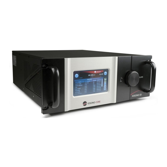
3. Hardware 3. HARDWARE Overview • Front Panel • Rear Panel Front Panel Front Panel The front panel contains the following elements: Image 3-1 IOSONO CORE front panel Item No. Function Power button Volume control Touch screen Rear Panel Rear Panel Image 3-2 IOSONO COREE rear view Number and kind of audio drawers depends on IOSONO CORE configuration. - Page 10 3. Hardware Item No. Element Element USB connectors Connection of USB storage devices for system backup and restore. Firmware update MAIN ethernet port Network connection to remote computer to control and setup the IOSONO CORE with the Control Unit software AUX ethernet port Not used COM port...
-
Page 11: System Start-Up
4. System Startup 4. SYSTEM STARTUP Initial Operation Initial Operation Your IOSONO CORE consists of electronic parts that may be sensitive to variations in temperature and humidity. Such variations could appear with changing the place of installation or by leaving the device unused for a longer period of time. To avoid harm to the device, always leave your device unpowered for a while. - Page 12 4. System Startup Image 4-1 Control Client 4.2.2 File Transfer File Transfer Files can be transmitted via the Control Client using the folder button in the lower right corner. The button opens a file browser. In the file browser, the left half shows the file structure of remote computer while the right half shows the accessible IOSONO CORE file structure.
- Page 13 4. System Startup Image 4-2 Easy Control user interface Item No. Function Result STOP button The active preset is stopped MUTE button The active preset is muted Configuration button The configuration display is activated Information button Call detailed information about the software version LOG button The log files of the IOSONO CORE can be stored on a USB storage device connected to one of the IOSONO...
- Page 14 4. System Startup R5906746 IOSONO CORE 08/05/2017...
-
Page 15: Initial System Configuration
5. Initial System Configuration 5. INITIAL SYSTEM CONFIGURATION Hardware Connections About To enter the Control Unit and make configurations, a remote computer (PC with Windows, laptop, ...) with Control Client installed and ethernet connection between remote computer and IOSONO CORE is needed. Please see "System Startup", page 7 for further details. - Page 16 5. Initial System Configuration Keep Type Rectangle Name your group, e.g. Ring Click OK to confirm (image 5-3) 4. Back in main window: in Group Type keep Multilayer checked, keep default Width and Length in Dimensions and type 1.5m in Height (value describes the absolute installation height of the speakers’ acoustical center above ground). 5.
- Page 17 5. Initial System Configuration 14.Press OK to leave the Options menu Image 5-2 Create Loudspeaker Setup view Image 5-3 Create a rectangular group R5906746 IOSONO CORE 08/05/2017...
- Page 18 5. Initial System Configuration Image 5-4 Create a surface group Image 5-5 Simple 3D model of a created loudspeaker setup Create A Test Preset 5.3.1 Noise About In this chapter a new preset will be created as preparation for running a line check to all connected signal components. R5906746 IOSONO CORE 08/05/2017...
- Page 19 5. Initial System Configuration Step-By-Step Guide 1. Press New and assign a Preset Name for example Noise Click OK to confirm 2. The view switches to the Preset Details tab with a tree structure on the left. Keep default values in General, make sure that in Loudspeaker Setup the previously created loudspeaker setup file 3D ls file is selected from the dropdown menu and Visibility has a check.
- Page 20 5. Initial System Configuration Click Stop in upper left corner of main window Image 5-6 Processing settings (noise) Image 5-7 Audo I/O Control status view R5906746 IOSONO CORE 08/05/2017...
- Page 21 5. Initial System Configuration 5.3.2 WAV Playback About This chapter uses the system setup as described in "Hardware Connections", page 11, the loudspeaker file from"Create A Loud- speaker File", page 11 and the noise preset from "Noise", page 14. It is advised to create a preset for dedicated purpose by copying and amending an already functional preset. This preset needs to contain a loudspeaker file as well as all general settings like described in previous chapters.
- Page 22 5. Initial System Configuration Toggle source Type from Plane to Point and listen to the results Note: Repeat procedure until you’re not experiencing a considerable volume difference at low frequencies (below 1 kHz). Therefore both source types need to be compared. The actual prefilter’s upper frequency value will most likely differ if you are using your own setup.
- Page 23 5. Initial System Configuration Image 5-9 Scene Designer view Image 5-10 Processing settings (Render Slot 1) R5906746 IOSONO CORE 08/05/2017...
- Page 24 5. Initial System Configuration R5906746 IOSONO CORE 08/05/2017...
-
Page 25: Control Unit
6. Control Unit 6. CONTROL UNIT Introduction 6.1.1 Graphic User Interface Overview About The graphic user interface of the Control Unit 3 is divided into two areas. The upper area is always visible and holds general system controls for starting and stopping a preset, as well as information about the currently selected preset, system name and volume. By default, the lower area shows the Home tab, which displays a list of all presets and their associated services. - Page 26 6. Control Unit Preset Details 6.2.1 General Preset Settings Image 6-2 General preset settings • Description: Text area to store and display notes regarding the current preset. • Sample Rate: Defines the sample rate, at which the IOSONO CORE is processing audio. Supported sample rates are 44.1 kHz, 48kHz and 96kHz (optional).
- Page 27 6. Control Unit 6.2.2.1 Filter Library About The filter library provides access to global filter configurations that are always linked to a particular loudspeaker file and that can be referenced by any preset with the same loudspeaker setup. The filters contained by filter configurations can either be designed with the System Tuning Extension or be created manually.
- Page 28 6. Control Unit IIR filters can be created and adjusted in real time, even while a preset is running, so you can listen to the resulting filters while you design them. The icon of each filter stage can be moved in the frequency response view to edit the filter stage.
- Page 29 Start by selecting the number of devices you want to use. In most cases this is the IOSONO CORE only, additional devices like processing extensions can be purchased from Barco. To add a device to the device list 1.
- Page 30 6. Control Unit 6.2.4 Services Image 6-4 General signal and scene data flow between sservices 6.2.5 Service Settings And Service Status Due to the modularity of the Control Unit each service has not only its own configuration page, but also displays information about its status in the currently running preset in a separate view.
- Page 31 6. Control Unit menu in the I/O Control settings tab, which can be used to route incoming audio signals directly to the physical outputs of the soundcard(s). 6.2.7 Processing About The Processing service is the heart of the IOSONO CORE, where audio signals will be rendered to the loudspeaker setup utilized in the preset according to the descriptive scene data.
- Page 32 About Extensions are software add-ons that come either free with every IOSONO CORE system or can be purchased from Barco individu- ally. These add-ons can be activated from the System - Options menu and provide additional features that are not tied to a specific preset.
- Page 33 6. Control Unit 6.3.2 Remote Control Extension About The Remote Control extension provides a network command line interface to the IOSONO CORE that enables third party pro- grammable, external media controllers to remote control the IOSONO CORE. The extension supports TCP and UDP connections via Ethernet and RS232 connections with an ASCII based message protocol.
- Page 34 6. Control Unit Command Parameters Return Value Description Returns maximum al- lowed sample- <integer> number of simulta- neous player/get_max_num_chan- playing channels nels Loads a sample from a file <integer> slot id sampleplayer/load_sample into the given slot. The path 0, <string> path to is relative to the base path sample file configured in the sampleplayer...
-
Page 35: Preset Management
6. Control Unit 6.3.2.5 Playback Status Messages About The following messages will be returned after sending remote command "player/get_playbackstate". Status Description Playback running :PLAYING: Playback paused :PAUSED: Playback stopped :STOPPED: 6.3.2.6 Playback Mode: Commands And Status Return Messages About The following command parameter are availabe for sending remote command "player/set_loopmode". The following status mes- sages will be returned after sending the command "player/get_loopmode". - Page 36 6. Control Unit 6.4.2 Revert A Preset About Changes to the configuration of a preset can be undone by using the revert function. A preset can be reverted to the state when it was last saved at any time using the Revert button in the Home tab. 6.4.3 Create And Restore Backups About...
- Page 37 7. Step-By-Step Configuration 7. STEP-BY-STEP CONFIGURATION Live Application 7.1.1 Hardware Connections About In this chapter we describe a scenario with a number of live input audio signals are fed in to the IOSONO CORE. Usually these signals are fed from a mixing console in a live event context. The mixing console may have MADI outputs connected to the IOSONO CORE or different output formats connected to a suitable signal converter which then is connected to the IOSONO CORE.
- Page 38 7. Step-By-Step Configuration 3. Create a group with + in Groups Select Type Standard Setups Name your group, for example Stereo PA Click OK to confirm in Group Type check Independent Note: See how the audience area is created in the scene display as a blue rectangle with red two speaker icons as well as a yellow screen line is inside it.
-
Page 39: Preset Configuration
7. Step-By-Step Configuration 13.Click OK to leave the option menu Image 7-2 Simple 3D model of the created loudspeaker setup 7.1.3 Preset Configuration 7.1.3.1 General Preset Configuration To configure a preset 1. In the Presets menu, press New and assign a Preset Name, e.g. Live Click OK to confirm 2. - Page 40 7. Step-By-Step Configuration Select loudspeaker group Stereo P.A. Select Panning in Algorithm Selection In Settings keep Level Correction on and Geometry Mode 2D (Ring), Delay Correction Mode Speaker Distance selected In Slot Settings uncheck the Source Traits dialog Note: For geometry mode, select the option that comes close to your loudspeaker group. If you’re not sure select Auto 2D/3D. The delay correction mode has two options - Speaker Distance and Source Distance: - Speaker Distance is optimized for ring shaped speaker groups.
- Page 41 7. Step-By-Step Configuration Image 7-3 Scene Designer Image 7-4 Scene Designer Image 7-5 R5906746 IOSONO CORE 08/05/2017...
- Page 42 7. Step-By-Step Configuration Image 7-6 7.1.3.3 Level and EQ using IIR-filtering About The preset described in "Create A Test Preset", page 14 uses a bass management configuration and several loudspeaker groups with differing acoustic properties. Therefore it is advisable to apply IIR-Filters to individual system components for leveling, separat- ing low frequency and full-range components and equalization (Find more information about IIR-filters in "Filter Creation", page 23).
- Page 43 7. Step-By-Step Configuration Click Filter Assignment to enable filter assignment mode Select loudspeakers (for selection of multiple speakers use shift+left mouse) in the loudspeaker group you wish to assign the HiPass filter to, for example the stereo pair loudspeakers in the Stereo P.A. group Click HiPass in IIR Filter List, the filters are now assigned to the selected speakers Click Filter Assignment again to turn it off Assign the HiPass filter in Loudspeaker Group Surrounds in the same way as described for Nearfills and Stereo P.A.
- Page 44 7. Step-By-Step Configuration Image 7-7 IIR filter settings Image 7-8 Filter assignment 7.1.3.4 Latency Minimization About In live applications the latency time of the reproduction system is always a critical issue. Below is a list that states sources of delay introduced by an IOSONO system, parameters that can be used to lower the system latency (latency minimization) and drawbacks that are introduced when setting parameters to allow for lowest system latency.
- Page 45 7. Step-By-Step Configuration Sources of latency Measures Drawbacks Do not use FIR-Filters. Less options of loudspeaker equalization. Pre delay Turn on minimum latency as a source Sources within the perimeter of the property in Scene Designer. system will not be not focused but reproduced by the loudspeakers closest to the source position.
- Page 46 7. Step-By-Step Configuration 7.2.3 Preset configuration About It is advised, that a preset for a dedicated purpose is created by copying and amending a functional preset already existing which contains a loudspeaker file and general settings as described in previous chapters. 7.2.3.1 ICF / IMF Playback About...
- Page 47 7. Step-By-Step Configuration Image 7-10 Typical wiring scheme for video/ICF/IMF playback To play back an ICF file in sync with LTC 1. Go to Preset tab Preset-Icon Select Icf Playback in Presets Copy the preset by pressing the Copy button Type Preset Name, for example Video playback press OK to confirm 2.
- Page 48 7. Step-By-Step Configuration Click the Status i-Icon Click + in the lower left corner Select the applicable content file Click Add Click Play-Icon Turn the Volume up with the + button in the top right corner Click the Edit-Icon in the lower part of the player window Set the desired Start Timecode point Click play at your external player with the video source The IOSONO CORE player starts playback according to the incoming timecode...
- Page 49 7. Step-By-Step Configuration In the matrix, scroll to the right to see/change the input routing Note: Make individual routing in the provided matrix if necessary or keep default diagonal line if your 5.1 stream is connected starting at input channel 1. The rows represent your input signals from the DVD/Blu-Ray Player at the audio input of the CORE and the columns represent the input channels to Render+ in the following order: 1 - Left 2 - Right...
- Page 50 7. Step-By-Step Configuration IOSONO Content Production About In an IOSONO content production setup, audio and scene data is delivered to the IOSONO CORE from an external computer running Nuendo and the Spatial Audio Workstation 2 Upmix! (SAW) plug-in. It is advised, that his computer has an audio connection to the IOSONO CORE via MADI using appropriate soundcards.
- Page 51 7. Step-By-Step Configuration 2. Select SAW in Presets list Go to tab Preset Details or double click SAW 3. Go to General in the tree structure on the left and make sure that Scene IP Address and Scene Port is the same as in SAW settings.
- Page 52 7. Step-By-Step Configuration R5906746 IOSONO CORE 08/05/2017...
-
Page 53: Advanced System Tuning With The System Tuning Extension
8. Advanced System Tuning With The System Tuning Extension 8. ADVANCED SYSTEM TUNING WITH THE SYSTEM TUNING EXTENSION About This chapter gives an overview about the process of acoustical tuning of an IOSONO system. The desired result of acoustical tuning is a system performing at its best with the given gear in the given space. - Page 54 8. Advanced System Tuning With The System Tuning Extension 3. In the Measurement tab select the Loudspeaker Setup representing the speaker setup that is supposed to be tuned, for example 3D ls file Understand and click Yes in the warning dialog In Group Name check all groups that should be measured and tuned, i.e.
-
Page 55: Microphone Placement
8. Advanced System Tuning With The System Tuning Extension Image 8-3 Measurement 8.3.1 Preparations About Following preparations should be done before performing correct measurement calibration of the measurement microphones. Adjust the microphone preamp gain of all channels individually, so that all microphones induce the same voltage when being exposed to the same SPL. - Page 56 8. Advanced System Tuning With The System Tuning Extension The software will ask the user to put the microphones to the next set of positions and go on with the measurement Click OK 4. Once the measurement is finished, you can access the impulse response for every loudspeaker measured at every microphone position Go to the loudspeaker setup display in the Measurement tab Select the desired speaker by left click...
- Page 57 8. Advanced System Tuning With The System Tuning Extension 2. Click on the Whitelist button on the right. This button will open a matrix called Measurement Whitelist containing all selected and measured speakers as rows and all measured microphone positions as columns. Select only green speaker cells - click OK to close the Whitelist dialogue.
- Page 58 8. Advanced System Tuning With The System Tuning Extension Image 8-5 Whitelist Image 8-6 Target curve view Image 8-7 Editing target curve and relevance scope R5906746 IOSONO CORE 08/05/2017...
- Page 59 8. Advanced System Tuning With The System Tuning Extension Image 8-8 Add/Remove/Copy filter kit curve settings Image 8-9 Filter kit parameters Image 8-10 Control buttons Filter Evaluation Filters can be evaluated in three different ways: 1. Listen to the system by alternating between applied and bypassed filters. To evaluate the filters subjectively, observe the whole frequency range by listening to a musical piece familiar to you.
- Page 60 8. Advanced System Tuning With The System Tuning Extension R5906746 IOSONO CORE 08/05/2017...
-
Page 61: Filter Library
9. Filter Library 9. FILTER LIBRARY About In Filter Library you can create Filter Configurations containing FIR and IIR filters that are each based on a particular loudspeaker setup. Each Filter Configuration can be used by any preset that is based on the same loudspeaker file. You can create, assign and adjust new IIR filters. - Page 62 9. Filter Library IIR Filter To create an IIR filter 1. In Loudspeaker Setup Select Live (or any other loudspeaker file which you wish to apply filters to) Understand and Click Yes in the warning dialog Create a New Filter in the IIR Filter List Name the IIR Filter for example HiPass 2.
-
Page 63: Specification And Technical Data
10. Technical Specifications 10. TECHNICAL SPECIFICATIONS About The information in this section is subject to change without notice. For current technical information, visit the product website or contact your sales support representative. 10.1 Technical Specifications Of The IOSONO CORE Specification And Technical Data Housing 19 in. - Page 64 10. Technical Specifications Hardware extension IOSONO CORE extension: extends the number of output channels by steps of 128 per extension. Two or more units can be connected to a IOSONO CORE processor which works as the head unit. Dimensions (W x H x D) 485 x 178 x 615 mm / 19 x 7 x 24.2 inches Installation depth (without connectors): 555 mm (21.9 in.) Weight...
-
Page 65: Environmental Information
For more information about recycling of this product, please contact your local city office or your municipal waste disposal service. For details, please visit the Barco website at: http://www.barco.com/en/AboutBarco/weee...
Need help?
Do you have a question about the Iosono Core R9801500 and is the answer not in the manual?
Questions and answers