Table of Contents
Advertisement
Quick Links
Advertisement
Table of Contents

Related Manuals for Control Techniques Nidec SI-EtherCAT


Summary of Contents for Control Techniques Nidec SI-EtherCAT
- Page 1 User Guide SI-EtherCAT Part Number: 0478-0152-05 Issue 5...
-
Page 2: Compliance Information
We are not required to file an annual conflict minerals disclosure. Nidec Control Techniques Limited is not an issuer as defined by the U.S. SEC Disposal and recycling (WEEE) When electronic products reach the end of their useful life, they must not be disposed of along with domestic waste but should be recycled by a specialist recycler of electronic equipment. - Page 3 The Nidec logo is a trade mark of Nidec Corporation. The Control Techniques logo is a trade mark owned by Nidec Control Techniques Limited. All other marks are property of their respective owners.
-
Page 4: Table Of Contents
Contents Safety information ..................6 Warnings, Cautions and Notes ................6 Installation and use ....................6 Enclosure .........................6 Competence of the installer ..................6 Repairs ........................7 Electric Shock and Fire Hazards ................7 Electrical installation ....................7 Setting up, commissioning and maintenance ............8 Safety of machinery, safety-critical applications ............9 1.10 Electromagnetic compatibility (EMC) ...............9 1.11... - Page 5 Advanced features ..................115 Distributed clocks ....................115 SI-EtherCAT protocol support ................117 Advanced Cyclic Data Task Configuration ............117 File over EtherCAT (FoE) ..................120 Functional Safety over EtherCAT (FSoE) ............121 Drive Type and Mode Override ................121 Parameter descriptions ................127 Internal menus .....................
-
Page 6: Safety Information
Safety information Warnings, Cautions and Notes A Warning contains information, which is essential for avoiding a safety hazard. WARNING A Caution contains information, which is necessary for avoiding a risk of damage to the product or other equipment. CAUTION A Note contains information, which helps to ensure correct operation of the product. NOTE Installation and use The information given in this publication is derived from tests and calculations on sample products. -
Page 7: Repairs
Repairs Users must not attempt to repair a drive if it is faulty. It must be returned to the supplier of the drive. Electric Shock and Fire Hazards WARNING - Dangerous voltage Where products are supplied by or connected to mains voltages, the voltages used can cause severe electrical shock and/or burns, and could be lethal. -
Page 8: Setting Up, Commissioning And Maintenance
WARNING - Fire Risk Braking resistors operate at very high temperatures for short periods. The following precautions are essential to avoid the risk of fire in the event of unexpectedly high braking energy or loss of control of the braking circuit. WARNING •... -
Page 9: Safety Of Machinery, Safety-Critical Applications
Automatic start Some parameter settings may cause the motor to start unexpectedly. Restore default parameter set Depending on the application, this may cause unpredictable or hazardous operation. Safety of machinery, safety-critical applications Within the European Union all machinery in which this product is used must comply with Machinery Directive 2006/42/EC. -
Page 10: Introduction
GmbH, Germany About SI-EtherCAT SI-EtherCAT is an option module that enables the Control Techniques Unidrive M range of variable speed drives to be connected to an EtherCAT network as a slave device. It can be used in a variety of applications, from those requiring accurate synchronization and precise motion control, to those where ease of use and open loop control are appropriate. -
Page 11: Option Module Identification
• File transfer over EtherCAT (FoE) • CANopen over EtherCAT (CoE) which includes: • Support of CANopen CiA402 • Cyclic sync position mode • Interpolated position mode • Velocity mode • Homing mode • One transmit and one receive PDOs via cyclic synchronous communication •... -
Page 12: Conventions Used In This Guide
Figure 2-2 SI-EtherCAT labels SI-EtherCAT 82400000018000 S/N: 3000005001 1710 Ser No : 3000005001 2.6.1 Date code format Before January 2017 The date code is split into two sections: a letter followed by a number. The letter indicates the year, and the number indicates the week number (within the year) in which the option module was built. -
Page 13: Mechanical Installation
Mechanical installation Before installing or removing an option module in any drive, ensure the AC supply has been disconnected for at least 10 minutes and refer to Chapter 1 Safety information on page 6. If using a DC bus supply ensure this is fully discharged before working on any drive or option module. -
Page 14: Electrical Installation
Electrical installation SI-EtherCAT module information 4.1.1 Bus media The SI-EtherCAT option module incorporates two 100 BASE-TX RJ45 interfaces. 4.1.2 Cabling considerations To ensure long-term reliability it is recommended that any cables used to connect a system together be tested using a suitable Ethernet cable tester, this is of particular importance when cables are constructed on site. -
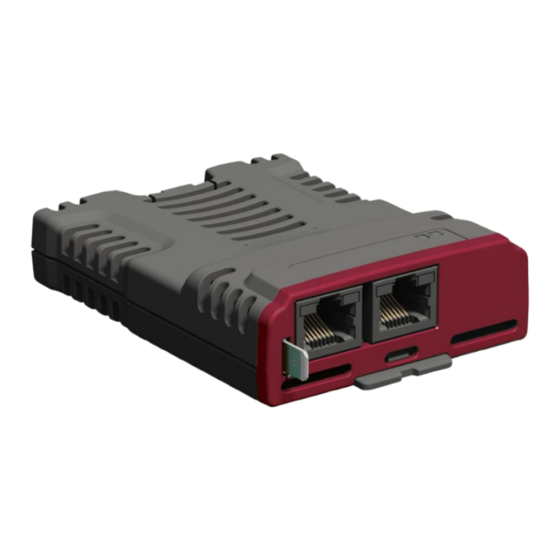
Page 15: Ethercat Terminal Descriptions
SI-EtherCAT terminal descriptions The SI-EtherCAT module has two RJ45 Ethernet ports for the EtherCAT network. Figure 4-1 SI-EtherCAT connections Link LEDs EtherCAT Port B Ground EtherCAT Port A Table 4-1 EtherCAT terminal descriptions A - IN B - OUT Transmit + Transmit + Transmit - Transmit -... -
Page 16: Network Topology
Ferrite core, Split type Network topology Control Techniques recommend implementing daisy chaining on EtherCAT networks (see Figure 4- 2). Other Ethernet network topologies can be used but care must be taken to ensure that the system still operates within the constraints specified by the designer. -
Page 17: Getting Started
5.1.1 SI-EtherCAT ESI file Control Techniques provides EtherCAT device description files (in the form of .xml files). These files provide the master with information about the SI-EtherCAT module and drive configuration to aid with its configuration. These files can be downloaded from the Control Techniques website or from your local Control Techniques Drive Centre or supplier. - Page 18 These PDOs contain the cyclic data (objects and/or parameters), the RxPDOs available are 1, 2, 3, 5 and 6, the TxPDOs available are 1, 2, 3, 5 and 6 (for more information on these PDOs including default mappings please see section 6.3.2 RxPDO mappings on page 34 and section 6.3.3 TxPDO mappings on page 39).
- Page 19 The format used to define the value of a mapped object is as follows: NOTE Bit 0 to 7: Length of the mapped object in bits (if a gap, bit length of the gap). Bit 8 to 15: Sub-index of the mapped object (if a gap, zero). Bit 16 to 31: Index of the mapped object (if a gap, zero).
- Page 20 Assigning RxPDO to the sync manager To assign RxPDO1 to sync manager 2 PDO assignment set the values below to the following objects: • Index: 0x1C12 • Sub index: 0x00 • Size: 1 • Value: 1 Setting object 0x1C12, sub-index 0 to a value of 1 (as above) indicates that one RxPDO will be assigned to the sync manager 2 assignment.
-
Page 21: Quick Start Flowchart
Quick start flowchart Figure 5-3 details the steps required to achieve cyclic communications on the EtherCAT network. This flowchart should be used as the starting point for all configurations. Figure 5-3 Quick start flowchart START Ensure the correct ESI files (xml files) package with the same revision number of the SI-EtherCAT firmware, together with the sub folders, are installed correctly on the master... -
Page 22: Supported Objects
Supported objects Table 5-3 lists the objects currently supported by SI-EtherCAT Table 5-3 SI-EtherCAT Object Dictionary Profile Data Type Object Ref. Description (0x) Sub- Type index 1000 Device type UDINT 1001 Error register USINT Error history USINT (Number of last-sub-index) 1003 Error history records 1 to N... - Page 23 Profile Data Type Object Ref. Description (0x) Sub- Type index Receive PDO mapping 10 USINT (Number of objects) 1609 Receive PDO mapping 10 1 to si0 UDINT (Mapped object 1 to si0) Transmit PDO mapping 1 USINT (Number of objects) 1A00 Transmit PDO mapping 1 1 to si0...
- Page 24 Profile Data Type Object Ref. Description (0x) Sub- Type index SM2 PDO assignment USINT (Number of PDOs) 1C12 SM2 PDO assignment UINT (Assigned PDO index) SM3 PDO assignment USINT (Number of PDOs) 1C13 SM3 PDO assignment UINT (Assigned PDO index) SM4 PDO assignment USINT (Number of PDOs)
- Page 25 Profile Data Type Object Ref. Description (0x) Sub- Type index Cyclic data loss behaviour USINT (Number of last sub-index) Cyclic data loss behaviour UINT (Timeout (ms)) Cyclic data loss behaviour UINT (Timeout (ms)) Cyclic Loss counter 3005 PDO loss re-arm delay UINT Max Weighted Internal SM event missed UINT...
- Page 26 Profile Data Type Object Ref. Description (0x) Sub- Type index vl_velocity_min_max_ amount USINT (Number of last sub-index) vl_velocity_min_max_ 6046 amount UDINT (Minimum velocity (rpm)) vl_velocity_min_max_ amount UDINT (Maximum velocity (rpm)) vl_velocity_acceleration USINT (Number of last sub-index) vl_velocity_acceleration 6048 UDINT (Delta speed value (rpm)) vl_velocity_acceleration UINT (Delta time value (s))
- Page 27 Profile Data Type Object Ref. Description (0x) Sub- Type index 6067 Position window UDINT 6068 Position window time UINT 606B Velocity demand value DINT 606C Velocity actual value DINT 6071 Target torque 6073 Max current UINT 6075 Motor rated current UDINT 6076 Motor rated torque...
- Page 28 Profile Data Type Object Ref. Description (0x) Sub- Type index Homing speeds USINT (Number of last sub-index) Homing speeds 6099 UDINT (Speed during switch search) Homing speeds UDINT (Speed during zero point search) 609A Homing acceleration UDINT Profile jerk (Number of last sub index) USINT 60A4 Profile jerk...
-
Page 29: Protocols
Protocols Process Data Objects (PDOs) Cyclic data is implemented on EtherCAT networks by using "Process Data Objects" or PDOs. Separate data objects are used for transmitting (TxPDOs) and receiving (RxPDOs) data. PDO configuration objects are usually pre-configured in the EtherCAT master controller and downloaded to the SI-EtherCAT at network Initialization using SDOs. -
Page 30: Canopen Over Ethercat (Coe)
CANopen over EtherCAT (CoE) The CoE protocol over EtherCAT uses a modified form of the CANopen object dictionary. This is specified in Table 6-2. Table 6-2 CoE object dictionary Index Object dictionary area 0x0000 to 0x0FFF Data type area 0x1000 to 0x1FFF CoE communication area 0x2000 to 0x5FFF Manufacturer specific area... - Page 31 <index> <object name> Sub-index n Access: <access> Range: <range> Size: <size> Unit: <N/A> Default: <default> Type: <Data Type> PDO mappable:<All/Rx/Tx/No> Update Rate: <when and how often> Description: <description> Definitions: • <index>: A 16-bit unsigned number. This is the index of the object dictionary entry. Specified in 4 hexadecimal digits.
- Page 32 Bit 17 (Servo Drive): y Bit 18 (Stepper Motor): 0 Bit 24 (DC Drive - Control Techniques specific): 0 Bits 25-31 (Manufacturer specific): 0 The device type value will be dependent on the drive operating mode and/or type. Bit 16 & 17 On High Performance drives in the open-loop, RFC-A or Regen modes or on General Purpose drives, bit 16 will be set, while bit 17 will be clear.
-
Page 33: Identity Object
Type: Unsigned integer / UDINT PDO Mappable: No Update Rate: N/A - Never changes This will contain the EtherCAT Technology Group vendor ID for Control Techniques. This is the Description: same value as the vendor ID used for SM-EtherCAT and SM-CANopen. - Page 34 If parameter S.00.049 is set to “Unidrive SP”, the product code will be as follows: Mode Product Code Open Loop 0x10003 RFC-A 0x30003 RFC-S 0x40003 Firmware V01.03.05.02 and earlier firmware versions indicated the module firmware NOTE version number. 6.3.2 RxPDO mappings Objects with indices from 0x1600 to 0x17FF specify receive PDO mappings.
- Page 35 Table 6-12 RxPDO mapping 1 0x1600 Receive PDO mapping 1 Sub-index 0: Number Of Mapped Objects Access: RW Range: 0 to 12 Size: 1 byte Unit: N/A Default: Type: Unsigned integer / USINT PDO Mappable: No Update Rate: PreOp -> SafeOp transition Description: The number of mapped objects in the PDO Sub-index 1: 1...
- Page 36 Table 6-14 RxPDO mapping 3 0x1602 Receive PDO Mapping 3 Sub-index 0: Number Of Mapped Objects Access: RW Range: 0 to 12 Size: 1 byte Unit: N/A Default: Type: Unsigned integer / USINT PDO Mappable: No Update Rate: Unsigned integer Description: The number of mapped objects in this PDO.
- Page 37 0x1604 Receive PDO Mapping 5 Sub-index 2: 2 Mapped Object Access: RW Range: N/A Size: 4 bytes Unit: N/A 0x60710010 - the CiA402 target Default: Type: Bit Mask / UDINT torque (0x6071). PDO Mappable: No Update Rate: PreOp -> SafeOp transition A mapping to an object.
- Page 38 Table 6-17 RxPDO mapping 8 0x1607 Receive PDO mapping 8 Sub-index 0: Number Of Mapped Objects Access: RW Range: 0 to 12 Size: 1 byte Unit: N/A Default: 1 (Regen mode), 0 other modes Type: Unsigned integer / USINT PDO Mappable: No Update Rate: PreOp ->...
- Page 39 6.3.3 TxPDO mappings Objects with the indices from 0x1A00 to 0x1BFF specify transmit PDO mappings. The following mappings from CiA402 are included as standard. Table 6-19 TxPDO mappings PDO number Mapping object index Mapping object name 0x6041 statusword 0x6041 statusword 0x6061 modes_of_operation_display 0x6041...
- Page 40 Table 6-21 TxPDO mapping 2 0x1A01 Transmit PDO mapping 2 Sub-index 0: Number Of Mapped Objects Access: RW Range: 0 to 12 Size: 1 byte Unit: N/A Default: Type: Unsigned integer / USINT PDO Mappable: No Update Rate: PreOp -> SafeOp transition Description: The number of mapped objects in this PDO.
- Page 41 0x1A02 Transmit PDO mapping 3 Sub-index 2: 2 Mapped Object Access: RW Range: N/A Size: 4 bytes Unit: N/A 0x60640020 - the CiA402 actual Default: Type: Bit Mask / UDINT position (0x6064) PDO Mappable: No Update Rate: PreOp -> SafeOp transition A mapping to an object.
- Page 42 Table 6-24 TxPD mapping 6 0x1A05 Transmit PDO mapping 6 Sub-index 0: Number Of Mapped Objects Access: RW Range: 0 to 32 Size: 1 byte Unit: N/A Default: Type: Unsigned integer / USINT PDO Mappable: No Update Rate: PreOp -> SafeOp transition Description: The number of mapped objects in this PDO.
- Page 43 Table 6-26 Transmit PDO Mapping 10 0x1A09 Transmit PDO Mapping 10 Sub-index 0: Number Of Mapped Objects Access: RW Range: 0 to 51 Size: 1 byte Unit: N/A Default: Type: Unsigned integer / USINT PDO Mappable: No Update Rate: PreOp -> SafeOp transition Description: The number of mapped objects in this PDO.
-
Page 44: Sync Manager Configuration
6.3.4 Sync manager configuration The sync managers are the EtherCAT means for setting access attributes for different areas of memory and triggering or notifying the application when the memory is accessed. The following objects specify how the sync managers (and thus corresponding memory areas) are utilized by the CoE protocol. - Page 45 0x1C00 Sync Manager Communication Type Sub-index 6 - Usage of Sync Manager 5 Access: RO Range: 4 Size: 1 byte Unit: N/A Default: Type: Unsigned integer / UDINT PDO Mappable: No Update Rate: N/A Never changes Sync Manager 5 is used by CoE as a slow/non-deterministic process data input (TxPDOs, Description: slave to master).
- Page 46 Table 6-30 Sync manager 4 PDO assignment object 0x1C14 Sync manager 4 PDO assignment Sub-index 0 Access: RW Range: 0 to 2 Size: 1 byte Unit: N/A Default: Type: Unsigned integer / USINT PDO Mappable: No Update Rate: PreOp -> SafeOp transition The number of RxPDOs assigned to this sync manager (used for non-deterministic Description: process data output).
- Page 47 Table 6-32 Sync manager 2 synchronisation 0x1C32 Sync manager 2 synchronisation Sub-index 0 Access: RO Range: 12 Size: 1 byte Unit: N/A Default: Type: Unsigned integer / USINT PDO Mappable: No Update Rate: N/A - Never changes Description: The highest sub-index supported. Sub-index 1: Synchronisation Type Access: RW Range: 0 to 2...
- Page 48 0x1C32 Sync manager 2 synchronisation Sub-index 8: Get Cycle Time Access: RO Range: 0 to 3 Size: 2 bytes Unit: N/A Default: Type: Unsigned Integer / UINT PDO Mappable: No Update Rate: Immediately actioned on SDO write Description: Get Cycle Time. If bit 1 is set the SM missed counter is reset to zero. Sub-index 9: Delay Time Access: RO Range: 0 upwards...
- Page 49 Table 6-33 Sync manager 3 synchronisation 0x1C33 Sync manager 3 synchronisation Sub-index 0 Access: RO Range: 12 Size: 1 byte Unit: N/A Default: Type: Unsigned / USINT PDO Mappable: No Update Rate: N/A - Never changes Description: The highest sub-index supported. Sub-index 1: Access: RO Range: 1 to 0x22...
- Page 50 Table 6-34 Sync manager 4 synchronisation 0x1C34 Sync manager 4 synchronisation Sub-index 0 Access: RO Range: 4 Size: 1 byte Unit: N/A Default: Type: Unsigned Integer / USINT PDO Mappable: No Update Rate: N/A - Never changes Description: The highest sub-index supported. Sub-index 1: Synchronisation Type Access: RO Range: 0...
-
Page 51: Ethernet Over Ethercat(Eoe)
6.3.5 Feedback encoder source Table 6-36 Feedback encoder source 0x3000 Position Feedback Encoder Configuration Access: RW Range: 0 to 11 Size: 1 byte Unit: N/A Default: Type: Unsigned Integer / USINT PDO Mappable: No Update Rate: On change of CiA402 profile This specifies the source for position controller feedback, and the source for CiA402 position Description: feedback objects. -
Page 52: Additional Position Loop Scaling
Some configuration of the PLC is required to establish the EoE tunnel which involves allocation of IP addresses to the EtherCAT modules and to allow forwarding of packets. This is documented with the PLC documentation. Some additional configuration of the routing tables within the PC is also required to allow the PC operating system to know to route the packets via the PLC. -
Page 53: Cyclic Data Loss Behaviour
Cyclic data loss behaviour When in EtherCAT Operational state regular updates of PDO data is expected from the Master. If these updates fail to occur (due to PDO data corruption, or lateness in arrival of the PDO) then old data will be reused. This can be a problem, if a motion profile is enabled then the next position, velocity or torque target value will not be available. - Page 54 0x3005 Cyclic data loss behaviour Sub-index 3: CiA402 Cyclic Data Missed Count Access: RO Range: 0 to 65535 Size: 2 bytes Unit: N/A Default: Type: Unsigned integer / UINT PDO Mappable: No Update Rate: On each PDO loss A count of the number of times the PDO data arrived late for the CiA402 motion profiles to use that data.
- Page 55 When the drive profiles have been disabled by setting Pr S.00.033 to ON, then Cyclic Data loss actions 0 & 1 will still raise a warning and trip respectively, but the motor will not be stopped as it is not under the control of EtherCAT. The table below shows the number of lost PDOs before the motor will be placed into the stopping state (0x3005:2 values 0 or 1) for each network cycle time.
-
Page 56: Drive Profile (Cia402) Support
Drive profile (CiA402) support SI-EtherCAT supports the following modes of the CiA402 profile: • Homing Mode • Cyclic Synchronous Position Mode • Interpolated Position Mode • vl velocity mode • Cyclic Synchronous Velocity Mode • Cyclic Synchronous Torque Mode • Profile Position Mode 0x6040 Controlword This provides the primary method of controlling the behavior of the drive e.g. -
Page 57: 0X6041 Statusword
Enable operation Fault reset NOTE: Automatic transition to Enable operation state after executing SWITCHED ON state functionality. There is a finite time needed by the drive, between setting the control word and the drive moving to that new state. This period is dependent on various factors, so it is advisable that any program after setting a new control word value, should poll the status word until the desired state has been reached. - Page 58 Table 7-5 State coding Statusword State xxxx xxxx x0xx 0000b Not ready to switch on xxxx xxxx x1xx 0000b Switch on disabled xxxx xxxx x01x 0001b Ready to switch on xxxx xxxx x01x 0011b Switched on xxxx xxxx x01x 0111b Operation enabled xxxx xxxx x00x 0111b Quick stop active...
-
Page 59: Common Profile Features
Common profile features 7.3.1 Sequencing control These are the supported objects used to control the drive: Table 7-6 Sequencing control supported objects Index Name 6040 Controlword 6041 Statusword 605B shutdown_option_code 605C disable_operation_option_code 605A quick_stop_option_code 605D halt_option_code 605E fault_reaction_option_code 6007 abort_connection_option_code 6060 modes_of_operation 6061... - Page 60 The mode_of_operation object is read in all CiA402 states so that the operating mode can be changed at any time, which is necessary for homing: some axes (e.g. vertical axes) have to be homed and start ordinary positioning operation without the need to remove power from the motor, which, on a vertical axis, might allow a tool, to fall and be damaged or cause damage.
- Page 61 Figure 7-1 CoE state machine diagram (Any Drive Trip) Start Fault Reaction Active Fault Reaction Profile SW& 0xFFB0 | 0x000F Complete Drive not tripped Fault Reset Fault Profile SW& 0xFFB0 | 0x000F Inhibit drive Not Ready To Switch On Drive Tripped? Profile SW &...
- Page 62 Table 7-7 CoE state machine transition and events Transition Event(s) Action(s) Automatic transition after power-on or reset Drive device self-test and/or self Initialization application shall be performed Automatic transition Communication shall be activated Shutdown command from control device or None local signal Switch on command received from control Power section shall be switched on if not...
- Page 63 7.3.2 0x605A Quick stop option code This object indicates what action is performed when the quick stop function is executed. The slow down ramp is the deceleration value of the used mode of operations. Table 7-8 Quick_stop_option_code 0x605A Quick_stop_option_code Access: RW Range: 0 to 6 Size: 2 bytes Unit: N/A...
- Page 64 Once a Quick stop reaction starts, it will complete before a fault reaction is applied (if the fault was not due to a drive trip). i.e. the Quick stop ramp will not change to the fault reaction ramp part way through the ramping.
- Page 65 Table 7-14 Disable_operation_option_code values Value Definition Disable drive function (switch off the drive power stage) Slow down with slow down ramp; disable the drive function 7.3.5 0x605D Halt_option_code This object shall indicate what action is performed when the halt function is executed. Table 7-15 Halt_reaction_option_code 0x605D Halt_option_code...
- Page 66 Table 7-18 Fault_reaction_option_code values Value Definition Disable drive function, motor is free to rotate Slow down on slow down ramp Slow down on quick stop ramp Option Code 1 and 2 will also wait for the brake to engage before Switch Off, if drive parameter 12.041 is enabled.
- Page 67 Value Definition No mode change Profile Position mode vl velocity mode 3 - 6 Reserved Homing mode Interpolated Position mode Cyclic Sync Position mode Cyclic Sync Velocity mode Cyclic Sync Torque mode The default for this object is dependent on the drive operating mode. In Open-loop the NOTE default is 2.
- Page 68 7.3.9 0x6061 Modes_of_operation_display This read only object indicates the active mode of operation. Table 7-21 Modes_of_operation_display 0x6061 Modes_of_operation_display Access: RO Range: 0 to 10 Size: 1 byte Unit: N/A Default: Type: Signed integer / SINT PDO Mappable: TxPDO Update rate: Every 40 ms Motion Profiles: ALL Description: Used to provide the active mode of operation.
- Page 69 Table 7-23 Profile deceleration 0x6084 Profile deceleration Access: RW Size: 4 bytes Unit: N/A Range:0 to 2 Default: 65536 Type: Unsigned integer / UDINT PDO Mappable: RxPDO Update Rate: See notes below Motion Profiles: IP, CSP, CSV, CST, HM, PP Description: Provides the deceleration ramp for the positioning modes IP, CSP.
- Page 70 7.3.12 Profile units The SI-EtherCAT implementation provides a means to convert profile units into position controller and drive units. All scaling values are standard profile objects. The following objects are supported: Table 7-25 Supported profile units Index Name 0x608F position_encoder_resolution 0x6091 gear_ratio 0x6092...
- Page 71 7.3.13 0x608F Position_encoder_resolution This read only object indicates the configured encoder increments per number of motor revolutions. The information is read from the drive's encoder configuration. Table 7-26 Position_encoder_resolution 0x608F Position_encoder_resolution Sub-index 0 Access: RO Range: N/A Size: 1 byte Unit: N/A Default: Type: Unsigned integer / USINT...
- Page 72 7.3.14 0x6091 Gear_ratio This object is used to apply scaling. When configured, appropriate user units can be used to control the position of the shaft beyond a gearbox. The gear ratio is calculated using the following formula: gear ratio = motor shaft revolutions / driving shaft revolutions Table 7-27 Gear_ratio 0x6091 Gear_ratio...
- Page 73 7.3.15 0x6092 Feed_constant This is used to configure a feed constant. This is the measurement distance per one revolution of the output shaft of the gearbox. The feed constant is calculated using the following formula: feed constant = feed / driving shaft revolutions Table 7-28 Feed_constant 0x6092 Feed_constant...
- Page 74 Table 7-29 Touch probe function supported objects Index Name 60B8 Touch probe function 60B9 Touch probe status 60BA Touch probe 1 positive edge 60BB Touch probe 1 negative edge 60D0 Touch probe source Table 7-30 Touch probe function 0x60B8 Touch probe function Access: RW Range: Bit Mask Size: 2 bytes...
- Page 75 Table 7-31 Touch probe status 0x60B9 Touch probe status Access: RO Range: N/A Size: 2 bytes Unit: N/A Default: Type: Bit Mask / UINT PDO Mappable: TxPDO Update rate: Every network cycle period Motion Profiles: When feedback encoder is available This indicates the status of the touch probe functionality;...
- Page 76 Table 7-34 Touch probe 1 positive edge 0x60BA Touch probe 1 positive edge Unit: User-defined Access: RO Range: N/A Size: 4 bytes position units Default: Type: Integer / DINT Update rate: When touch probe 1 is triggered by PDO Mappable: TxPDO positive edge.
- Page 77 Here are two example timing diagrams, to explain the operation sequence of the touch probe function: Figure 7-2 Trigger first event (0x60B8 bit1 = 0) Figure 7-3 Continuous (0x60B8 bit1 = 1) SI-EtherCAT User Guide...
- Page 78 7.3.17 Basic position control Basic position control is supported on the Unidrive M70x and Digitax HD in RFC-A and RFC-S modes. The position control described here is used under the interpolated position mode of operation. Table 7-36 lists the objects that are supported: Table 7-36 Basic position control supported objects Index Name...
-
Page 79: Position Window
7.3.20 0x6065 Following error window This object can be used to indicate and configure the range of position values, symmetrical to the position demand value, outside of which a following error occurs. The value is given in user-defined position units. Table 7-39 Following error window 0x6065 Following error window... - Page 80 7.3.23 Motor rated current This object indicates the configured motor rated current. The value is given in mA. Table 7-43 0x6075 Motor rated current 0x6075 Motor rated current Access: RW Size: 4 bytes Unit: mA Range: 0 to 2 Default: Derived from Pr 05.007 Type: Unsigned integer / UDINT PDO Mappable: No...
- Page 81 7.3.26 0x60F4 Following_error_actual_value This read only object provides the actual value of the following error. The value is given in user- defined position units. Table 7-46 Following_error actual_value 0x60F4 Following_error actual_value Access: RO Size: 4 bytes Unit: N/A Range: -2 to 2 Default: Type:Signed integer / DINT...
-
Page 82: Supported Drive Modes
7.3.28 Supported Drive Modes This object provides information on the supported drive modes. Table 7-48 Supported Drive Modes 0x6502 Supported drive modes Sub-index 0 Access: RO Range: Bit Mask Size: 4 bytes Unit: N/A Default: Type: Bit Mask / UDINT PDO Mappable: No Update rate: Reset Motion Profiles: ALL... - Page 83 7.4.2 0x60C1 Interpolation_data_record This object is used to specify the target position. Linear interpolation is used to generate position demand values every 250 µs. The position is specified in user-defined position units. The value is written into sub-index 1. Table 7-51 0x60C1 Interpolation_data_record 0x60C1 Interpolation_data_record Sub-index 0...
-
Page 84: Vl Velocity Mode
The implementation of interpolated position mode allows synchronous operation only, where a fixed, common interpolation interval is defined. The time specified must always be an integer multiple of the control loop cycle time. The time period index has a minimum value of -6 (i.e. the smallest time unit will be microseconds), see Table 7-53 for more information. - Page 85 7.5.1 Activate velocity mode redirection This object provides the facility to redirect the velocity mode reference from the normal velocity mode object (0x6042) to the cyclic sync velocity mode object (0x60FF). Table 7-55 Activate velocity mode redirection 0x3008 Activate velocity mode redirection Access: RW Range: 0 to 1 Size: 1 byte...
- Page 86 7.5.4 0x6044 vl_velocity_actual_value This read only object provides the velocity at the motor spindle or load. In a closed loop system this is determined from the motor feedback device and in an open loop system it is derived from the drive’s estimated velocity.
- Page 87 7.5.6 0x6048 vl_velocity_acceleration This object is used to configure the delta speed and delta time of the slope of the acceleration ramp. Example: To ramp to 1000 rpm in 5 s, possible values for delta speed and delta time are 10000 and 50 respectively.
- Page 88 7.5.7 0x6049 vl_velocity_deceleration This object is used to configure the delta speed and delta time of the slope of the deceleration ramp. Example: To decelerate by 800 rpm in 10 s, possible values for delta speed and delta time are 8000 and 100 respectively.
- Page 89 7.5.8 0x604A vl_velocity_quick_stop This object is used to configure the delta speed and delta time of the slope of the deceleration ramp for quick stop. Example: To decelerate by 800 rpm in 10 s, possible values for delta speed and delta time are 8000 and 100 respectively.
- Page 90 7.5.9 0x604B vl_setpoint_factor This object is used to configure the numerator and denominator of the vl_setpoint_factor. The vl_setpoint_factor modifies the resolution or directing range of the specified setpoint. It does not influence the velocity limit function and the ramp function. A value of 0 must not be used. Table 7-63 0x604B vl_setpoint_factor 0x604B vl_setpoint_factor...
- Page 91 7.5.10 0x604C vl_dimension_factor This object is used to configure the numerator and denominator of the vl_dimension_factor. The vl_dimension_factor is used to scale the user units so that they can be used in a way that relates to the specific application. Calculating the vl_dimension_factor: Every user-specific velocity consists of a specific unit referred to as a specific unit of time (e.g.
-
Page 92: Homing Mode
deceleration rate preset is changed (Pr 02.021), the vl_velocity_deceleration object is updated. Homing mode This section describes the method by which a drive seeks the home position (also called, the datum, reference point or zero point). Figure 7-4 shows the defined input objects as well as the output objects. The user may specify the speeds, acceleration and the method of homing. - Page 93 Figure 7-5 Homing on positive home switch and index pulse Method 5 and 6: Homing on negative home switch and index pulse Using these methods as shown in Figure 7-6 Homing on negative home switch and index pulse on page 93, the initial direction of movement shall be dependent on the state of the home switch. The home position shall be at the index pulse either to the left or the right of the point where the home switch changes state.
- Page 94 Figure 7-7 Homing on home switch and index pulse - positive initial motion Figure 7-8 Homing on home switch and index pulse - negative initial motion Method 15 and 16: Reserved These methods are reserved. Method 17 to 30: Homing without index pulse These methods are similar to methods 3 to 14 except that the home position is not dependent on the index pulse but only dependent on the relevant home transitions.
- Page 95 Figure 7-9 Homing on positive home switch Method 31 and 32: Reserved These methods are reserved. Method 33 and 34: Homing on index pulse Using these methods, the direction of homing is negative or positive respectively. The home position shall be at the index pulse found in the selected direction as shown in Figure 7-10 Homing on index pulse on page 95.
- Page 96 Table 7-66 Definition of bit 10, 12 and 13 of statusword Bit 13 Bit 12 Bit 10 Definition Homing procedure is in progress. Homing procedure is interrupted or not started. Homing is attained, but target is not reached. Homing procedure was completed successfully. Homing error occurred, velocity is not 0.
- Page 97 0x3003 Homing source object Sub-index 4 Access: RW Range: 0 to 255 Size: 1 byte Unit: N/A Default: Type: Unsigned integer / USINT Update Rate: New value used on CiA402 PDO Mappable: No transition to SWITCH_ON Parameter to be used for the source of homing switch (0 = none). Also, sub-index 1 needs to be Description: set to zero.
- Page 98 0x6098 Homing method This object indicates the configured homing method that shall be used. The following two tables specify the object description and the value ranges for this object. Table 7-69 Homing method 0x6098 Homing method Sub-index 0 Access: RW Range: 0 - 37 Size: 1 byte Unit: N/A...
-
Page 99: Homing Acceleration
0x6099 Homing speeds This object indicates the configured speeds used during the homing procedure. The values shall be given in user-defined velocity units. The following table specifies the object description. Table 7-71 Homing speeds 0x6099 Homing speeds Sub-index 0 Access: RO Range: 2 Size: 1 byte Unit: N/A... - Page 100 When using one of the CiA402 positioning modes, Distributed Clocks must be enabled. NOTE Failure to do so may result in the SI-EtherCAT module going into the SAFE- OPERATIONAL state. Cyclic sync position mode provides linear interpolation which will always insert a delay of one position command.
- Page 101 The implementation of cyclic sync position mode will provide linear interpolation, which will always cause a delay of one operating mode cycle. The time specified must always be an integer multiple of the control loop cycle time; this will be checked. Every interpolator time period, a value will be read from the target position object, and the interpolator will generate a new position command to the control loops, every control loop cycle (between the current and new position).
-
Page 102: Cyclic Synchronous Velocity Mode
Cyclic Synchronous Velocity Mode Cyclic Synchronous Velocity mode will be supported on Unidrive M600 and above in RFC-A and RFC-S operating modes. On Unidrive M600 and above, this profile will operate on the control loop cycle time, using the drive's AMC speed reference (which is read by the drive every 250 , and the AMC will be µs configured to run in velocity mode). -
Page 103: Velocity Offset
7.8.3 0x60B1 Velocity offset This object is used to specify the velocity offset value. The value is given in user-defined units. Table 7-80 Velocity offset 0x60B1 Velocity offset Sub-index 0 Access: RW Size: 4 bytes Unit: N/A Range: -2 to 2 Default: Type: Signed integer / DINT PDO Mappable: RxPDO... -
Page 104: Maximum Current
7.9.2 0x6073 Maximum current This object is used to specify the maximum current value. The value is given in user-defined units. Table 7-82 Maximum current 0x6073 Maximum current Access: RW Range: 0 to 65535 Size: 2 bytes Unit: 0.1 % Default: Derived from Pr 04.007 Type: Unsigned integer / UINT... -
Page 105: Torque Offset
7.9.5 0x60B2 Torque offset This object is used to specify the torque offset value. The value is given in user-defined units. Table 7-85 Torque offset 0x60B2 Torque offset Range: -32768 to Access: RW Size: 2 bytes Unit: 1/10 of a percentage 32767 Default: Type: Signed integer / INT... -
Page 106: Profile Position Mode
7.10 Profile Position Mode The profile position mode is only supported on Unidrive M70X and Digitax HD (M75X) drives in RFC-A or RFC-S modes.The profile position mode allows the user to execute point-to-point positioning using the drive position profile generator. The setting of setpoints is controlled by the timing of the Control word bits b4 (NEW SETPOINT) and b5 (CHANGE SETPOINT IMMEDIATELY). - Page 107 Control word usage The Control word for the profile position mode differs from the standard configuration as shown below. Table 7-86 Profile Position Mode control word usage Bits b15-b10 b3-b0 Name CHANGE ON HALT ABSOLUTE CHANGE SETPOINT NEW SET- SETPOINT or RELATIVE IMMEDIATELY POINT...
- Page 108 Figure 7-12 Profile position setpoint example (CHANGE SETPOINT IMMEDIATELY = 1) SI-EtherCAT User Guide...
- Page 109 Figure 7-13 Profile position setpoint example (CHANGE SETPOINT IMMEDIATELY = 0) In addition to the common supported objects, the following Profile Position mode specific objects are supported: Table 7-88 Profile Position mode supported mode specific objects Index Name 0x6067 Position window 0x6068 Position window time 0x606B...
- Page 110 7.10.1 0x606B Velocity Demand ValuePosition window time The Velocity Demand Value object shows the velocity output of the trajectory generator in user units. Table 7-89 Velocity Demand Value 0x606B Torque offset Access: RO Size: 4 bytes Unit: User units Range: -2 to 2 Default: Type: Signed integer / DINT...
- Page 111 7.10.3 0x607D Software position limit This object allows the user to configure a software position limits. Table 7-91 Software Position Limit 0x607D Software Position Limit Sub-index 0 Access: RO Range: N/A Size: 1 byte Unit: N/A Default: Type: Unsigned integer / USINT PDO Mappable: No Update rate: N/A Motion Profiles: PP...
-
Page 112: Max Acceleration
7.10.6 0x60A4 Profile jerk This object is supported in the profile position mode only and specifies the jerk rate to be applied. Table 7-94 Profile Jerk 0x60A4 Profile Jerk Sub-index 0 Access: RO Range: N/A Size: 1 byte Unit: N/A Default: Type: Unsigned integer / USINT PDO Mappable: No... - Page 113 7.10.9 0x60F2 Positioning option code This object is supported in the profile position mode only, it allows the user to configure the behaviour of the positioning system and is evaluated when the profile position mode is selected and on a transition in state from READY TO SWITCH ON to SWITCHED ON. Table 7-97 Positioning Option Code 0x60F2 Positioning Option Code...
- Page 114 A movement greater than the limit (more than 1 revolution) is allowed only if both bits b6 and b7 are set to 0 (i.e. normal mode). If the target position is larger than the maximum position range limit, or it is negative, it is automatically converted to the equivalent modulo position. For example, referring to the Normal example above, if the target position requested was 450, then the converted target position would be: Requested target position...
-
Page 115: Advanced Features
Advanced features Distributed clocks SI-EtherCAT supports Distributed clocks. This is the scheme used by EtherCAT to accurately time synchronize slave devices. Position, speed and current control loops can all be synchronized. When the option module is connected to a drive which can take a time synchronization signal (e.g. a Unidrive M600 or above), the EtherCAT Distributed Clocks facility can be used to provide this signal so the drive speed and current tasks are synchronized to the network. - Page 116 Figure 8-1 Profile Cycle Timing 250µs OptSync Interrupt time Drive Sync Waveform (OptSync) Profile Cycles 62.5µs* Control Loop Cycles (current torque) This time can vary according to drive frequency (which can change during operation to reduce temperature in drive) Critical Task (task length varies with amount of data...
-
Page 117: Ethercat Protocol Support
SI-EtherCAT protocol support The following are supported: • Four Sync Managers. Two are used for the Mailbox Protocol (non-cyclic data) and two are used for process data (cyclic data) • Distributed Clocks • CANopen over EtherCAT (CoE) • Functional safety over EtherCAT (FSoE) Advanced Cyclic Data Task Configuration This configuration will allow the timing behaviour of the synchronous cyclic data handling to be modified;... - Page 118 The copy of the data to ma OPT_SYNC is an internal signal used for synchronisation purposes on drives that support synchronisation. OPT_SYNC occurs every 250 µs and can be synchronised with the EtherCAT network event SYNC0 (which occurs at a rate dependent on network cycle time configured in the master). For example, if the network cycle time is 1 ms.
- Page 119 Table 8-4 In cyclic data configuration 0x3007 In cyclic data configuration Sub-index 0 Access: RO Range: 2 Size: 1 byte Unit: N/A Default: Type: Unsigned integer / USINT PDO Mappable: No Update Rate: N/A - Never changes Description: The number of the last sub-index in this object. Sub-index 1 Access: RW Range: 0 to 2...
-
Page 120: File Over Ethercat (Foe)
Drive parameters or option module parameters are stored in a binary format file type called Parameter Difference File which is only readable by a Control Techniques drive or option module. They can be uploaded and saved as they are without file extensions. -
Page 121: Functional Safety Over Ethercat (Fsoe)
EtherCAT firmware file being downloaded to the connected EtherCAT option module using the online firmware update function. The EtherCAT firmware file is .img file provided by Control Techniques. Which can be downloaded to the following file path in the EtherCAT option module: /fw/app Follow the instructions of the controller's user guide to activate the firmware download. - Page 122 Table 8-5 Product codes in Unidrive SP override Drive Mode Value RFC-A 0x30003 RFC -S 0x40003 Open Loop 0x10003 Regen Same as before, no over-ride of product code Objects Mapped To Parameters That May Not Exist In A Unidrive M When in Unidrive SP override, the following parameters will be available (via the CoE object mapping mechanism) that may or may not exist on the drive (depending on the model).
- Page 123 Table 8-8 Objects that are scaled to be the same as Unidrive SP Object / Corresponding Unidrive SP parameter name - for the corresponding menu/ Subindex Unidrive SP parameter parameter number 0x2003:10 Pr 3.10 Speed Controller proportional Gain Kp1 0x2003:34 Pr 3.34 Rotary Lines per Revolution x02003:46...
- Page 124 Object / Corresponding Unidrive SP parameter name - for the corresponding menu/ Subindex Unidrive SP parameter parameter number 0x200C:07 Pr 12.07 Threshold detector destination 0x200C:08 Pr 12.08 Variable Selector source 0x200C:09 Pr 12.09 Variable Selector source 0x200C:11 Pr 12.11 Variable Selector destination 0x200C:23 Pr 12.23 Variable Selector source...
- Page 125 8.6.2 Mode agnostic When Pr S.00.049 is set to "Mode Agnostic" (2) override is selected, the Object 0x1018:02 reports a mode agnostic product code. i.e., the same product code for all modes. This allows an EtherCAT master to change the drive mode, without the slave product code changing and thereby avoiding the error that the slave seems to have changed.
- Page 126 8.6.5 Window Filter A window filter before interpolation can be enabled when the application requires. If the window filter is enabled, the target values are fed through a window filter, the output of that window filter is then the input to the interpolation. Table 8-10 Window Filter Size 0x300A Window Filter Size...
-
Page 127: Parameter Descriptions
Parameter descriptions It is intended that it is not necessary to use option module parameters for EtherCAT setup or control of a drive; parameters are mostly provided for status and information. This means that a user will configure the motor and feedback in the usual way, using parameters, install an EtherCAT option, and use CoE;... -
Page 128: Single Line Parameter Descriptions
Single line parameter descriptions Table 9-3 Menu 0 parameters (Set-up) Size Parameter Range Default Access (Bits) S.00.000 Parameter mm.00 0 to 65535 S.00.001 Module ID 0 to 65535 00.00.00.00 to S.00.002 Firmware version 99.99.99.99 S.00.003 Hardware version 0 to 65535 S.00.004 Serial number LS 0 to 99999999... -
Page 129: Default Access
Table 9-4 Menu 1 parameters (EtherCAT Status) Size Parameter Range Default Access (Bits) S.01.000 Parameter mm.00 0 to 65535 0 (Unknown State) S.01.001 EtherCAT RUN indicator to 8 (Op) S.01.002 PDO Accesses per second 0 to 65535 S.01.004 Mapped parameter xx.000 0 to 65535 S.01.005 FSoE Msgs per second... - Page 130 Table 9-7 Menu 9 parameters (Resources) Parameter Range Default Access Size (Bits) S.09.000 Parameter mm.00 0 to 65535 S.09.009 Background Task Period 0 to 65535 S.09.010 Pre-critical task % free 0 to 100 S.09.011 Critical task % free 0 to 100 S.09.012 Post-critical task % free 0 to 100...
-
Page 131: Full Parameter Descriptions
Full parameter descriptions 9.4.1 Menu 0 (Setup) - Corresponds to menu 15, 16 or 17 This menu will provide some common fieldbus option parameters used for basic housekeeping and information. Table 9-8 Module ID S.00.001 Module ID Minimum Maximum 65535 Default Units Type... - Page 132 Table 9-12 Serial number MS S.00.005 Serial Number MS Minimum Maximum 99999999 Default Units Type 32 bit volatile Update Rate Power-up write Display Format None Decimal Places Coding RO, ND, NC, PT, BU See Serial Number LS (S.00.004). Table 9-13 Status S.00.006 Status Minimum...
- Page 133 Table 9-16 Default S.00.008 Default Minimum 0 (Display: Off) Maximum 1 (Display: On) Default Units Read every 200 ms Type 1 bit volatile Update Rate Written to 0 when save is complete Display Format Decimal Places Coding RW, Bit, NC If set to "ON"...
- Page 134 Table 9-19 Slot indicator S.00.031 Slot Indicator Minimum Maximum Default Units Type 8 bit volatile Update Rate Written on power-up Display Format None Decimal Places Coding RO, ND, NC, PT, BU The parameter displays the number of the virtual option slot on the drive that the module is connected to.
- Page 135 Table 9-22 Allow EEPROM Upgrade S.00.034 Allow EEPROM Upgrade Minimum 0 (Display: Off) Maximum 2 (Display: Force Default) Default Units Type 1 bit User Save Update Rate Read in background Display Format Decimal Places Coding RW, Bit This allows the data in the EtherCAT configuration EEPROM to be upgraded, and it does this by preventing the EtherCAT ASIC from accessing the EEPROM, so that the processor can access it;...
- Page 136 Table 9-26 Sync OUT consistency trigger parameter S.00.037 Sync OUT Consistency Trigger Parameter Minimum 0 (Display: 0.00.000) Maximum 1 (Display: 9.99.999) Default 0 (Display: 0.00.000) Units None Type 32 bit User Save Update Rate EtherCAT state transition Display Format Decimal Places Coding RW, DE The SI-EtherCAT module provides an output consistency feature for the synchronized cyclic data...
- Page 137 Table 9-29 Consistency trigger for non-synchronous outputs S.00.040 Consistency trigger for non-synchronous outputs Minimum 0 (Display: Off) Maximum 1 (Display: On) Default 0 (Display: Off) Units None Type 1 bit User Save Update Rate EtherCAT state transition Display Format Decimal Places Coding RW, Bit See Consistency trigger for non-synchronous outputs (S.00.041) for details...
- Page 138 When the input consistency is enabled in Consistency trigger for non-synchronous inputs (S.00.042), this configured parameter is used to control the data exchange, ensuring skew does not occur; a user program, etc, must check the configured parameter is 0 before writing the data to be transmitted over the EtherCAT network, and it should set the parameter to 1 after all the data has been written.
- Page 139 It is not recommended to use this parameter (leave set to value 0), only use if it is really necessary for backwards compatibility purposes. This parameter will be subject to change between releases, ask Control Techniques for further details if required.
- Page 140 9.4.2 Menu 1 (EtherCAT Status) This menu provides status information on the EtherCAT network. Table 9-38 EtherCAT RUN Indicator S.01.001 EtherCAT RUN Indicator Minimum Maximum Default Units Type 8 bit volatile Update Rate Background Display Format Text Decimal Places Coding RO, Txt, ND, NC, PT This parameter displays the EtherCAT Run state, as required by the EtherCAT Indicator and Marking Specification.
- Page 141 Table 9-41 Mapped Parameter xx.000 S.01.004 Mapped Parameter xx.000 Minimum Maximum 65535 Default Units Type 16 bit volatile Update Rate Background Display Format None Decimal Places Coding RW, ND, NC, PT, BU This parameter is mapped to parameter Pr 13.000, Pr 09.000, Pr 02.000, Pr 01.000, to allow this parameter to be accessed using a CoE object (mapped CoE object indices correspond to menu numbers, and sub-object indices correspond to parameter numbers;...
- Page 142 Table 9-45 Fast Watchdog S.01.007 Fast Watchdog Minimum Maximum Default Units Type 8 bit volatile Update Rate Read in background Display Format Standard Decimal Places Coding This parameter enables or disables the Fast Watchdog. When enabled (set to On), if the SI- EtherCAT module should fail (e.g.
- Page 143 9.4.3 Menu 2 (Ethernet over EtherCAT Status) This menu provides information on the Ethernet over EtherCAT configuration. Table 9-47 EoE Status S.02.003 EoE Status Minimum Maximum Default None Units None Type 8 bit volatile Update Rate On EtherCAT Initialization Display Format Text Decimal Places Coding...
- Page 144 Table 9-51 EoE Subnet Mask S.02.007 EoE Subnet Mask 4294967295 Minimum Maximum (Display: 000.000.000.000) (Display: 255.255.255.255) Default None Units Type 32 bit volatile Update Rate On EtherCAT Initialization Display Format Decimal Places Coding RO, ND, NC, PT, BU This parameter displays the subnet mask of the module, as set by EoE. Table 9-52 EoE Default Gateway S.02.008 EoE Default Gateway...
- Page 145 9.4.4 Menu 3 (CiA402 Motion Profiles) This menu provides information on CiA402 motion profiles Table 9-54 CiA402 Home status S.03.002 CiA402 Home status Minimum Maximum Default Units Type 1 bit volatile Update Rate Background Display Format Standard Decimal Places Coding RO, ND, NC, BU A Status indicator.
-
Page 146: Menu 9 (Resources)
9.4.5 Menu 9 (Resources) This menu provides information on the SI-EtherCAT module resources. Table 9-57 Background Task Period S.09.009 Background Task Period Minimum Maximum 65535 Default None Units Type 16 bit volatile Update Rate Written in background Display Format Standard Decimal Places Coding RO, ND, NC, PT, BU... - Page 147 Table 9-61 Pre-critical task worst % free S.09.020 Pre-critical task worst % free Minimum Maximum Default None Units Type 8 bit volatile Update Rate Written in background Display Format Standard Decimal Places Coding RO, ND, NC, PT This parameter shows the worst case resource available for the pre-critical task. Table 9-62 Critical task worst % free S.09.021 Critical task worst % free...
- Page 148 This parameter shows the margin in microseconds between when the TxPDO data has been received from the network and when the values have been applied to the hardware. A negative value indicates data is too late (and hence used in the next cycle). Table 9-66 PCB Temperature S.09.030 PCB Temperature...
- Page 149 Table 9-70 Values of Diagnostic Counter Selector Value Text Description No Counter Selected to be displayed Port A Inv Errs Port A Invalid Frame Receive Error Counter Port B Inv Errs Port B Invalid Frame Receive Error Counter Port A Rx Errs Port A Receive Error Counter Port B Rx Errs Port B Receive Error Counter...
- Page 150 Table 9-74 Object Index view Selector 1 S.09.050 Object Index view Selector 1 Minimum Maximum 65535 Default Units Type 16 bit volatile Update Rate Written in background Display Format Standard Decimal Places Coding RO, ND, NC, PT This parameter selects a CAN Object Index to view in Object View Value 1 (S.09.052). The CAN Object Subindex also need to be configured in Object Subindex View Selector 1(S.09.051).
- Page 151 Table 9-78 Object Subindex view Selector 2 S.09.054 Object Subindex view Selector 2 Minimum Maximum Default Units Type 8 bit volatile Update Rate Written in background Display Format Standard Decimal Places Coding RW, NC, PT This parameter selects a CAN Object Subindex to view in Object View Value 2 (S.09.055). Table 9-79 Object View Value 2 S.09.055 Object View Value 2...
- Page 152 Table 9-82 Object View Value 3 S.09.058 Object View Value 3 Minimum -2147483648 Maximum 2147483647 Default Units Type 32 bit volatile Update Rate Written in background Display Format Standard Decimal Places Coding RO, NC, NC, PT This parameter shows the value of object view selector 3. SI-EtherCAT User Guide...
-
Page 153: Diagnostics
Diagnostics 10.1 Module identification parameters 10.1.1 SI-EtherCAT module ID code Table 10-1 SI-EtherCAT module ID code SI-EtherCAT module ID code Default 431 (SI-EtherCAT) S.00.001 Range 0 to 65535 Access The module ID code indicates the type of module installed in the slot. This is useful for checking the module is of the correct type. -
Page 154: Error Register
Table 10-5 Error Register 0x1001 Error Register Access: RO Range: N/A - Bit Mask Size: 1 byte Unit: N/A Default: Type: Bit Mask / USINT PDO Mappable: No Update Rate: On error A non-zero value in this object indicates that an error has occurred. The bit(s) set indicate the type of error present. - Page 155 Value Text Description 0x4312 Excess temperature drive 23 - OHt Control 0x4313 Excess temperature drive 24 - Thermistor 0x4314 Excess temperature drive 27 - OHt dc bus 0x4315 Excess temperature drive 101 - OHt Brake "Supply low voltage" and "U2 = 0x5112 91 - User 24 V supply +24 V"...
- Page 156 Value Text Description 0x7600 Data storage (external) 174 - Card Slot 0x7601 Data storage (external) 175 - Card Product 0x7603 Data storage (external) 177 - Card User Prog 0x7604 Data storage (external) 178 - Card Busy 0x7605 Data storage (external) 179 - Card Data Exists 0x7606 Data storage (external)
-
Page 157: Error History
Table 10-10 Error code 0x1003 Error History Sub-index 0 Access: RW Range: 0 to 10 Size: 1 byte Unit: N/A Default: Type: Unsigned integer / USINT PDO Mappable: No Update Rate: On error The number of the last sub-index in this object. A value of zero can be written to Description: sub-index 0 to clear the array of last errors Sub-index 1 to N... -
Page 158: Drive Trip Display Codes
10.4 Drive trip display codes Table shows the possible trip codes that will be displayed on the drive when a problem is detected with SI-EtherCAT or when SI-EtherCAT initiates a trip. Table 10-12 Trip display codes Value Display text Description (Pr 10.070) Invalid Fdbk Src An unknown or invalid feedback source has been configured... -
Page 159: Option Module Trips
10.5 Option module trips Table 10-13 Option module trips Value Display Text Description (Pr 10.070) SW fault Software Fault BG Orun Background task overrun FW invalid Invalid firmware for hardware version Drv unknown Unknown drive type Drv unsupported Unsupported drive type Mode unknown Unknown drive mode Mode unsupported... -
Page 160: Updating Si-Ethercat Firmware
10.7 Updating SI-EtherCAT firmware The latest SI-EtherCAT firmware is available from your local Control Techniques Drive Centre or supplier. To upload firmware to SI-EtherCAT a copy of Unidrive M Connect and a suitable communications lead for the option module's host drive is required. - Page 161 Code Meaning Description Comment (0x) Sync Manager for input process 001E Invalid input configuration Use correct Sync Manager data is invalid Invalid watchdog The watchdog configuration is 001F Check watchdog setting configuration invalid Slave device requires a cold 0020 Slave needs cold restart Restart the slave device restart or power cycle Slave application requests INIT...
-
Page 162: Sdo Abort Codes
10.10 SDO abort codes SDO messages use a request-response mechanism and the EtherCAT master will always expect a response from the slave device. If an error occurs with an SDO transfer SI-EtherCAT will return an SDO abort code to indicate the reason for the failure, the SDO abort codes are listed in Table 10-16. -
Page 163: Glossary Of Terms
Glossary of terms Address: This is the unique network identification given to a networked device to allow communication on a network. When a device sends or receives data the address is used to determine the source and the destination of the message. Bit: A binary digit, this may have the value of 1 or 0. - Page 164 PLC: Programmable logic controller. Poll rate: The rate at which cyclic data is sent and received on the network. Polled data: See Cyclic data. Scan rate: See Poll rate. Shielding: A connection to provide additional immunity to noise used on a network cable. Status word: A value that denotes the status of the drive.
- Page 165 Index Address ....................163 Bit ......................163 Byte ......................163 Cautions .......................6 Control word .....................163 Cyclic data ....................163 Cyclic sync position mode ................99 Cyclic Synchronous Velocity Mode ............102 Data rate ....................163 Device ......................163 Diagnostics ....................153 Distributed clocks ..................115 Double word .....................163 Earthing / grounding .................163 Electrical installation ...................14 Electrical safety ....................6 Features .....................10...
- Page 166 Octet ......................163 Option module ....................10 Parameter descriptions ................127 PC ......................163 PLC ......................164 Poll rate ....................164 Polled data ....................164 Products covered by this User Guide ............10 Quick start guide ..................17 Safety information ..................6 Scan rate ....................164 Shielding ....................164 SI-EtherCAT Object Dictionary ..............22 SI-EtherCAT terminal descriptions .............15 Status word ....................164 Supported objects ..................22...
- Page 167 ©2024 Nidec Control Techniques. The information contained in this document is for guidance only and does nor form part of any contract.The accuracy cannot be guaranteed as Nidec Control Techniques Ltd have an ongoing process of development and reserve the right to change the specification of their products without notice.
Need help?
Do you have a question about the Nidec SI-EtherCAT and is the answer not in the manual?
Questions and answers