
Related Manuals for Control Techniques UD55


Summary of Contents for Control Techniques UD55
- Page 1 User Guide UD55 UD55 Cloning interface small option module for Unidrive Commander GP Part Number: 0460 - 0095 Issue Number: 3...
- Page 2 These differences will cause a difference in functions. This may also apply to variable speed drives returned from a Control Techniques Service Centre. If there is any doubt, contact a Control Techniques Drive Centre. Copyright © January 2002 Control Techniques Drives Ltd...
-
Page 3: Table Of Contents
Saving Parameters Loading Parameters Loading a Parameter-set from the UD55 Transferring parameter-sets between Drives of different ratings Using the UD55 with other small option modules Avoiding problems with inter-related parameters Erasing the entire flash memory of the UD55 Related parameters... - Page 4 UD55 User Guide Issue code: 55nu3...
-
Page 5: Introduction
Drive. Installation The UD55 must be fitted in the small option module bay of the Unidrive. All connections to the Drive are made by a multi-way connector. Connections from external equipment are made to a plug-in 16-way screw-terminal block on the UD55. -
Page 6: Safety Information
To ensure mechanical safety, additional safety devices such as electro-mechanical interlocks may be required. The Drive must not be used in a safety-critical application without additional high-integrity protection against hazards arising from a malfunction. UD55 User Guide Issue code: 55nu3... -
Page 7: Environmental Limits
Drive. Damage may occur, or lives put at risk. Carefully follow the instructions in this User Guide. Before making adjustments to the Drive, ensure all personnel in the area are warned. Make notes of all adjustments that are made. UD55 User Guide Issue code: 55nu3... -
Page 8: Risk Analysis
Some parameters have a profound effect on the operation of the Drive. They must not be altered without careful consideration of the impact on the controlled system. Measures must be taken to prevent unwanted changes due to error or tampering. UD55 User Guide Issue code: 55nu3... -
Page 9: Inserting The Ud55 In A Drive
Inserting the UD55 in a Drive Before following these instructions, refer to the Warnings and Notes at the beginning of Chapter 3 Setting up the Drive in the Unidrive User Guide. Warning The power terminals of the Drive retain a high voltage... - Page 10 Disconnect the supply from the Drive. Check that the exterior of the UD55 is not damaged, and that the multi-way connector is free from dirt and debris. Do not fit a damaged or dirty UD55 in a Drive. Remove the terminal cover from the Drive (for removal instructions, see Installing the Drive in Chapter 2 of the Unidrive Installation Guide).
-
Page 11: Making Connections
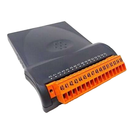
Making Connections Locations of the terminals Figure 2 Location of the plug-in terminal block on the UD55 Functions of the terminals Terminal Function To enable the save function, terminals 40 and 41 should be directly connected together 42 to 55... -
Page 12: Saving Parameters
If a small option module was fitted in the Drive, its associated Menu 16 parameters will be copied to the UD55 in addition to the parameters in the other menus. Insert the UD55 in the source Drive (refer to Chapter 3, Inserting the UD55 in a Drive). - Page 13 Remove the terminal cover. Disconnect the link between terminals 40 and 41 on the UD55 connector. Remove the UD55 from the Drive. If a small option module was previously fitted in the Drive, re-fit the module. Replace the terminal cover.
-
Page 14: Loading Parameters
Appendix A, Diagnostics. Ensure the destination Drive is configured in the same operating mode as the source Drive. (The UD55 cannot change the operating mode of the Drive.) Ensure terminals 40 and 41 on the UD55 are not connected. -
Page 15: Transferring Parameter-Sets Between Drives Of Different Ratings
Remove the UD55 from the Drive; if no other small option module is required in the Drive, the UD55 can remain permanently fitted. If required, fit a small option module. Replace the terminal cover. The Drive can now be used. -
Page 16: Using The Ud55 With Other Small Option Modules
Using the UD55 with other small option modules When a UD55 is fitted to the Drive it replaces any small option module that may have been fitted previously. If parameters were last saved in the Drive with a small option module fitted, other than a UD55, then menu 16 will be present and visable via the keypad when a UD55 is subsequently fitted. -
Page 17: Erasing The Entire Flash Memory Of The Ud55
Erasing the entire flash memory of the UD55 Ensure terminals 40 and 41 on the UD55 are connected. Insert the UD55 in a Drive (refer to Chapter 3, Inserting the UD55 in a Drive). Ensure terminal 30 of the Drive Signal connector is open-circuit so that the Drive does not become enabled when powered-up. -
Page 18: Related Parameters
0 ~ 16383 RO Uni When parameter values are copied to the UD55, a checksum is calculated from all the parameter values. 11.40 contains the value of the checksum of the parameter values contained in the parameter-set selected in 11.38. -
Page 19: Diagnostics
FSH.Err The UD55 memory has been found to be corrupt. If the trip has been produced at power-up then the memory of the UD55 is automatically reformatted and all parameter-sets are erased. If errors are detected after power-up, the trip will occur but the memory of the UD55 will not be reformatted automatically. - Page 20 UD55 User Guide Issue code: 55nu3...
Need help?
Do you have a question about the UD55 and is the answer not in the manual?
Questions and answers