
Subscribe to Our Youtube Channel
Related Manuals for Control Techniques SM-Resolver


Summary of Contents for Control Techniques SM-Resolver
- Page 1 User Guide SM-Resolver Solutions Module for Unidrive SP Part Number: 0471-0015-04 Issue Number: 4...
- Page 2 Drive software version The SM-Resolver can only be used with drive software version 01.01.00 onwards. Copyright © September 2004 Control Techniques Drives Ltd...
-
Page 3: Table Of Contents
Solutions Module identification ..............7 Set-up parameters .................. 8 Compatible resolver types ............... 8 Operation of a resolver ................9 Installing the SM-Resolver .......... 11 Solutions Module slots ................11 Installation ..................... 11 Terminal descriptions ................12 Wiring, Shield connections ..............13 Getting started ............. -
Page 4: How To Use This Guide
This guide contains information covering the identification of the Solutions Module, terminal layout for installation, fitting of the Solutions Module to the drive, parameter details and diagnosis information. Additional to the aforementioned are the specifications of the Solutions Module. SM-Resolver User Guide www.controltechniques.com Issue Number: 4... -
Page 5: Safety Information
- for example, an over-speed protection device in case of failure of the speed control, or a fail-safe mechanical brake in case of loss of motor braking. SM-Resolver User Guide Issue Number: 4 www.controltechniques.com... -
Page 6: Environmental Limits
Some parameters have a profound effect on the operation of the drive. They must not be altered without careful consideration of the impact on the controlled system. Measures must be taken to prevent unwanted changes due to error or tampering. SM-Resolver User Guide www.controltechniques.com Issue Number: 4... -
Page 7: Introduction
Features The SM-Resolver provides an interface for a resolver to be connected to the Unidrive SP, to be used as position and speed feedback for the drive. The SM-Resolver also provides a simulated quadrature encoder output. The SM-Resolver will only provide speed and position feedback when it is selected as NOTE the source of the drive speed/position feedback. -
Page 8: Set-Up Parameters
Set-up parameters All parameters associated to the SM-Resolver can be found in either menu 15, 16, or 17. Each of menus 15, 16, and 17 refer to one of the available slots into which the SM- Resolver can be fitted. See Figure 4-1 on page 11. -
Page 9: Operation Of A Resolver
Zero position Zero position 3.5.1 Direction of rotation Forward rotation is defined as follows: Motor Phase sequence: U V W Resolver COS modulation leads the SIN modulation (by 90°) (see Figure 3-4) SM-Resolver User Guide Issue Number: 4 www.controltechniques.com... - Page 10 Figure 3-4 Modulation and carrier-phase conditions around the zero position of the resolver Resolver position Excitation (primary) secondary Carrier in anti-phase with excitation Carrier in phase with excitation secondary Carrier in phase with excitation Carrier in phase with excitation Zero position of resolver SM-Resolver User Guide www.controltechniques.com Issue Number: 4...
-
Page 11: Installing The Sm-Resolver
2. Ensure that both the +24V, and +48V backup power supplies are disconnected from the drive for at least 10 minutes if used. 3. Check that the exterior of the SM-Resolver is not damaged, and that the multi-way connector is free from dirt and debris. -
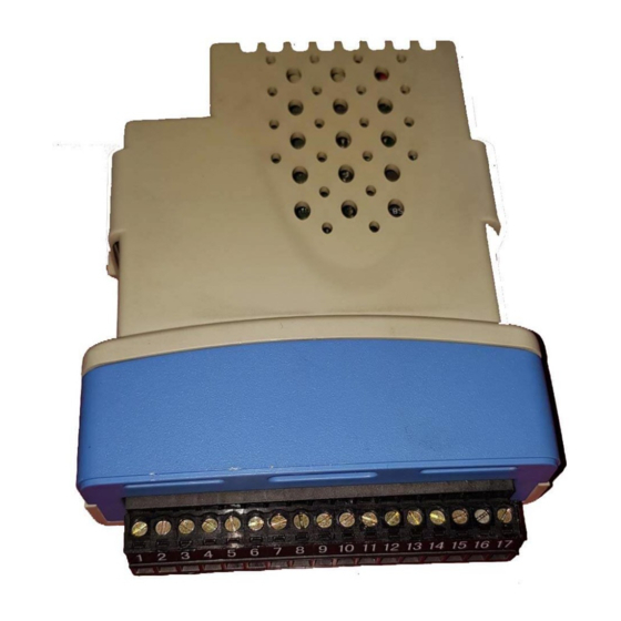
Page 12: Terminal Descriptions
11. Check that Pr 15.01, Pr 16.01 or Pr 17.01 shows the correct code for the SM- Resolver (code = 101). 12. If the checks in steps 10 and 11 fail, either the SM-Resolver is not fully inserted, or the Solutions Module is faulty. -
Page 13: Wiring, Shield Connections
Note that the resolver provides inherent galvanic isolation of the signal connections from ground. This means that no special provisions are required in order to provide surge immunity for cables exceeding 30m. SM-Resolver User Guide Issue Number: 4 www.controltechniques.com... - Page 14 Figure 4-6 Feedback Cable, Twisted Pair Cable overall shield Twisted pair Cable cable Twisted pair shield Ensure that feedback cables are kept as far away as possible from power cables and NOTE avoid parallel routing. SM-Resolver User Guide www.controltechniques.com Issue Number: 4...
-
Page 15: Getting Started
Ensure that the drive and motor are connected as per the instructions given in Chapter 4 Electrical Installation in the Unidrive SP User Guide, and that the resolver feedback wiring and shielding recommendations are followed in section 4.4 Wiring, Shield connections on page 13. SM-Resolver User Guide Issue Number: 4 www.controltechniques.com... -
Page 16: Solutions Module Set-Up
6-pole set Pr x.15 = 2 • 8-pole set Pr x.15 = 3 Enable the SM-Resolver as the drive position / speed feedback by setting Enable SM-Resolver Pr 3.26 to Slot1 (1), Slot2 (2) or Slot3 (3) depending on the location of the Solutions Module. -
Page 17: Encoder Simulation Output
The freeze flag does not re-set itself. Before carrying out consecutive freeze functions, the freeze flag must be cleared by the user (Pr x.39 = "OFF") on both the SM-Resolver, the source of the freeze, and any additional associated Solutions Module.. -
Page 18: Parameters
The parameters listed in this chapter are used for programming and monitoring the SM- Resolver. The SM-Resolver is classed as a dumb module as it does not have its own processor and as a result all parameters are updated by the drive processor. - Page 19 Not cloned: not transferred to or from smart cards during cloning. Protected: cannot be used as a destination. User save: saved in drive EEPROM when the user initiates a parameter save. Power-down save: automatically saved in drive EEPROM at power-down. SM-Resolver User Guide Issue Number: 4 www.controltechniques.com...
-
Page 20: Single Line Descriptions
No function x.38 No function x.39 Freeze flag OFF (0) or On (1) OFF (0) RW Bit x.40 No function x.41 No function x.42 No function x.43 No function x.44 No function SM-Resolver User Guide www.controltechniques.com Issue Number: 4... - Page 21 0 to 255 RO Uni NC PT status x.51 No function Read / Write Read only Unipolar Bi-polar Bit parameter Text string Filtered Destination Not cloned Rating dependent Protected User save Power down save SM-Resolver User Guide Issue Number: 4 www.controltechniques.com...
- Page 22 Figure 6-1 SM-Resolver logic diagram Resolver selected as drive feedback 3.26 Term Resolver connections Equivalent SIN LOW x.10 lines per SIN HIGH revolution COS LOW Resolver COS HIGH x.13 excitation REF HIGH (excitation) REF LOW (excitation) Resolver x.15 poles x.17...
- Page 23 Simulated encoder Resolver Term x.05 x.25 output connections source Encoder 3.29 source x.xx Input Read-write (RW) 0.XX terminals parameter Read-only (RO) Output 0.XX parameter terminals The parameters are all shown at their default settings SM-Resolver User Guide Issue Number: 4 www.controltechniques.com...
-
Page 24: Parameter Descriptions
Module fitted where one was previously fitted, the drive gives a Slot.dF or SLot.nf trip. x.03 Speed feedback ±40,000.0 rpm Update rate: 4ms x number of dumb modules Provided the set-up parameters for the position feedback are correct this parameter shows the speed in rpm. SM-Resolver User Guide www.controltechniques.com Issue Number: 4... - Page 25 6kHz, 12kHz The internal update time for the speed Pr x.03 when used as feedback runs at level 2 as NOTE follows. Update time Switching frequency Level 3kHz, 4kHz, 6kHz, 250µs 8kHz, 12kHz, 16kHz SM-Resolver User Guide Issue Number: 4 www.controltechniques.com...
- Page 26 3:1 (0), 2:1 (1 or 2) 3:1 (0) Update rate: Background read The excitation level can be controlled for use with 3:1 ratio resolvers (Pr x.13 = 0), or 2:1 ratio resolvers (Pr x.13 = 1 or 2). SM-Resolver User Guide www.controltechniques.com Issue Number: 4...
- Page 27 Wire break detect Error detection disabled Wire break detect Error detection disabled Wire break detect The wire break trip is not activated provided one signal is >1.5Vrms or both are >0.2Vrms NOTE approximately. SM-Resolver User Guide Issue Number: 4 www.controltechniques.com...
- Page 28 Resolver resolution Pr x.25 14 bit 12 bit 10 bit 0.0000 to 0.0312 1/32 0.0313 to 0.0625 1/16 0.0626 to 0.1250 0.1251 to 0.2500 0.2501 to 0.5000 0.5001 to 3.0000 SM-Resolver User Guide www.controltechniques.com Issue Number: 4...
- Page 29 OFF (0) or On (1) Update rate: Background write At power-up Pr x.45 is initially OFF (0), but is set to On (1) when the SM-Resolver can provide position feedback. Pr x.45 then remains at On (1) whilst the drive is powered-...
- Page 30 90°C, the drive fan is forced to operate at full speed (for a minimum of 10s). If the temperature falls below 90°C, the fan can operate normally again. If the PCB temperature exceeds 100°C, the drive is tripped and the error status is set to 74. SM-Resolver User Guide www.controltechniques.com Issue Number: 4...
-
Page 31: Diagnostics
Status Mode Alarm Status Trip Status Healthy Status Drive status = tripped Trip type (UU = undervolts) Figure 7-2 Location of the status LED Status LED Non flashing: Flashing: Normal status Trip status SM-Resolver User Guide Issue Number: 4 www.controltechniques.com... - Page 32 2. Ensure Solutions Module is fitted correctly 3. Replace Solutions Module 4. Save parameters and reset drive The SM-Resolver will only provide speed and position feedback when it is selected as NOTE the source of the drive speed/position feedback. Hence the SM-Resolver does not function when the drive is operating in open-loop mode.
-
Page 33: Terminal Data
Simulated encoder output channel Z Simulated encoder output channel Z\ Type EIA485 differential voltage Maximum frequency 500kHz Absolute maximum applied voltage relative to ±14V Minimum marker pulse width 300ns Protection Current limit with thermal protection SM-Resolver User Guide Issue Number: 4 www.controltechniques.com... - Page 34 4V rms (turns ratio = 2:1) Absolute maximum applied DC voltage (REF ±36V HIGH) with reference to 0V Absolute maximum applied current (REF LOW) 200mA Protection Over-current protection Total current for all 0V terminals of Solutions 200mA Module SM-Resolver User Guide www.controltechniques.com Issue Number: 4...
-
Page 35: Index
Internal update time ................... 25 Keypad status modes ................. 31 Logic diagram ..................... 22 Marker ......................17 Maximum speed ..................16 Notes ......................5 Operating resolution ................... 26 Operation of a resolver ................. 9 SM-Resolver User Guide Issue Number: 4 www.controltechniques.com... - Page 36 Solutions Module ID code ................24 Solutions Module set-up ................16 Temperature monitoring circuit ..............30 Terminal data ....................33 Terminal descriptions .................12 Trip history ....................31 Turns ratio ....................8 Update time ....................18 Warnings ......................5 Wire break trip ....................27 Wiring connections ..................13 SM-Resolver User Guide www.controltechniques.com Issue Number: 4...
- Page 38 0471-0015-04...
Need help?
Do you have a question about the SM-Resolver and is the answer not in the manual?
Questions and answers