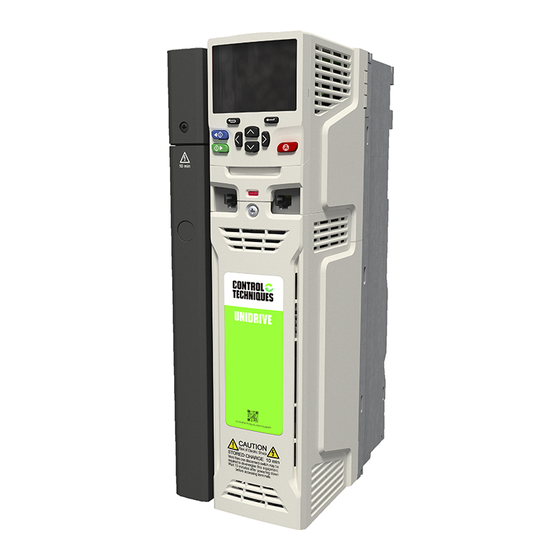
Summary of Contents for Control Techniques Modbus RTU
- Page 1 User Guide: Communications module Profinet Profibus Modbus TCP Modbus RTU Ethernet/IP DeviceNet For use with D1/D2 soft starters...
- Page 2 Product Compatibility This communications module is suitable for use with Digistart D1 and D2 soft starters. For the latest manuals and software, please visit our website.
-
Page 3: Table Of Contents
Contents Disclaimer .......................... 2 Important User Information ....................2 Warnings ..........................2 Installation ......................... 3 Connection ........................4 Device Configuration ......................4 LEDs ........................... 5 Operation ........................... 5 Modbus Registers ......................6 Modbus Control via Remote Operator ................8 Specifications ........................9 User Manual... -
Page 4: Disclaimer
Disclaimer Modbus RTU Module Disclaimer The examples and diagrams in this manual are included solely for illustrative purposes. The information contained in this manual is subject to change at any time and without prior notice. In no event will responsibility or liability be accepted for direct, indirect or consequential damages resulting from the use or application of this equipment. -
Page 5: Installation
Modbus RTU Module Installation Installation CAUTION Remove mains and control voltage from the soft starter before attaching or removing accessories. Failure to do so may damage the equipment. Installation Procedure 1. Remove control power and mains supply from the soft starter. -
Page 6: Connection
Connection Modbus RTU Module Connection For the soft starter to accept fieldbus commands, a link must be fitted across terminals A1-02 on the starter. Soft starter A1, 02: Stop input Modbus RTU Module RS-485 connection onto Modbus network Device Configuration Adjustment Network communication parameters must be set on the Modbus Module. -
Page 7: Leds
Modbus RTU Module LEDs LEDs The Network Status LED (1) indicates the state of the communications link between the module and the network. LED operation is as follows: Soft starter not powered up Communication active Flashing Communication inactive NOTE If communication is inactive, the soft starter may trip if the Communications Timeout function has been set on the module. -
Page 8: Modbus Registers
Modbus Registers Modbus RTU Module Modbus Registers Register Description Bits Details 40002 Command 0 to 2 To send a command to the starter, write the (single write) required value: 1 = Start 2 = Stop 3 = Reset 4 = Quick stop (coast to stop) - Page 9 Modbus RTU Module Modbus Registers Examples Command: Start Message Starter Function Register Data Address Code Address 40002 CRC1, CRC2 40002 CRC1,CRC 2 Starter state: Running Message Starter Function Register Data Address Code Address 40003 CRC1, CRC2 xxxx0011 CRC1, CRC2 Trip code: Motor overload...
-
Page 10: Modbus Control Via Remote Operator
Modbus Control via Remote Operator Modbus RTU Module Modbus Control via Remote Operator The Modbus Module can be used to connect a Remote Operator to the soft starter, enabling control via an RS-485 serial communications network. See the Remote Operator instructions for details on connecting the Remote Operator to the starter. -
Page 11: Specifications
Network ......... 5-way male and unpluggable female connector (supplied) Maximum cable size ................... 2.5 mm • Settings Protocol ..................Modbus RTU, AP ASCII Address range ...................... 0 to 31 Data rate (bps) ................ 4800, 9600, 19200, 38400 Parity ..................None, Odd, Even, 10-bit Timeout .......... - Page 12 7 1 0 - 2 1 3 7 8 - 0 0 A 7 1 0 - 2 1 3 7 7 - 0 0 A 7 1 0 - 2 1 3 7 6 - 0 0 A 7 1 0 - 2 1 3 7 5 - 0 0 A 7 1 0 - 2 1 3 7 4 - 0 0 A 7 1 0 - 2 1 3 7 3 - 0 0 A 7 1 0 - 2 1 3 7 2 - 0 0 A...


Need help?
Do you have a question about the Modbus RTU and is the answer not in the manual?
Questions and answers