
Related Manuals for DAKOTA ULTRASONICS MAX II


Summary of Contents for DAKOTA ULTRASONICS MAX II
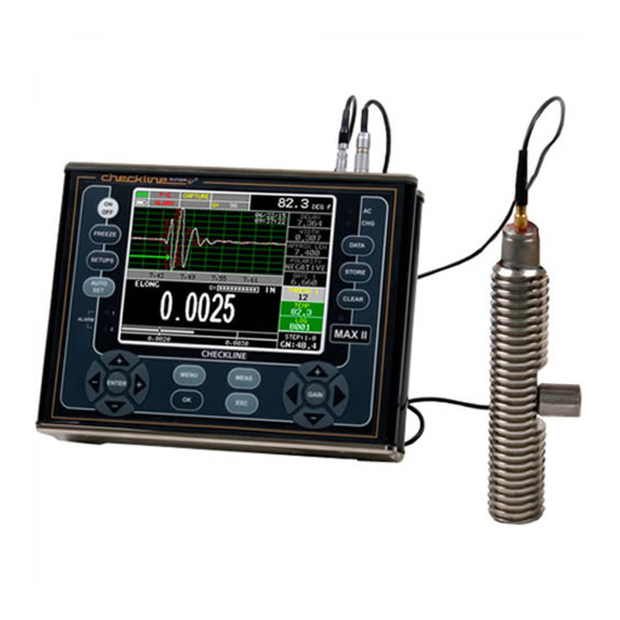
- Page 1 OPERATION MANUAL DAKOTA ULTRASONICS MAX II Ultrasonic Bolt Tension Monitor P/N P-197-0002 Rev 1.13, January 2022 GlobalTestSupply www. .com Find Quality Products Online at: sales@GlobalTestSupply.com...
-
Page 2: Table Of Contents
ARRANTY CHAPTER TWO ABOUT THIS MANUAL ............3 2.1 N ? ....................... 3 LTRASONICS 2.2 N ? ..................3 EW TO FASTENER MEASUREMENT 2.3 MAX II O ........................ 3 VERVIEW 2.4 T & S ....................6 UBMENU EFERENCE CHAPTER THREE QUICK START GUIDE ............8 ... - Page 3 ....................38 OTTOM CHAPTER FIVE THEORY OF OPERATION ............ 40 5.1 U ................40 LTRASONIC EASUREMENT OF OLTS 5.2 F MAX II ....................40 EATURES OF THE 5.3 U ......................41 LTRASONIC WAVES 5.4 M ...................... 41 EASUREMENT ODES CHAPTER SIX BOLT PREPARATION ............43 ...
- Page 4 10.3 S ..................80 TRESS FACTOR CALIBRATION 10.4 T ................84 EMPERATURE ACTOR ALIBRATION CHAPTER ELEVEN LOAD MEASURMENT ........... 87 11.1 C .................... 87 ALCULATING ACTOR 11.2 C ) ............89 ALIBRATING ACTOR IELD ALIBRATION 11.3 P .................. 90 ERFORMING A IELD ALIBRATION CHAPTER TWELVE MEASUREMENT &...
- Page 5 CHAPTER SIXTEEN SOFTWARE, FILE TRANSFER, & UPGRADES ..186 16.1 C ................186 OMPUTER YSTEM EQUIREMENTS 16.2 I ..................... 186 NSTALLING 16.3 C MAX II ..................186 OMMUNICATING WITH 16.4 U XFER (MAX II) ................... 187 SING THE MENU 16.5 S ..................187 ELECTING...
-
Page 6: Chapter One Introduction
The responsibility for proper use of the instrument rests solely on the user. 1.2 Safety Using the MAX II while standing in water or in a wet environment can result in serious electric shock, injury, and even death. Operating the MAX II with damaged or inadequate cables and power source can result in serious electric shock, injury, and even death. -
Page 7: Warranty
Use of the MAX II for any other purpose, or in any other manner than described in this manual invalidates the warranty and can result in serious electric shock, injury, and even death. -
Page 8: Chapter Two About This Manual
By measuring the stretch of the fastener and knowing the physical properties of the fastener, the load of the fastener can be calculated. The MAX II measures the fastener stretch by ultrasonically measuring the change in length. - Page 9 Dakota Ultrasonics In order to understand how to operate the MAX II, it’s best to start off with an understanding of what it is we’re looking at exactly. The MAX II has a lot of great features, tools, and flexibility to assist you with all of your bolting applications. Let’s have a brief look at the screens you’ll be looking at most often:...
- Page 10 MAX II Bolt Tension Monitor D. Alarm – Indicates that the alarm feature has been activated and currently in use. E. RF A-Scan Display (split screen) – Displays the radio frequency sound wave reflection returned the opposite end of the bolt being measured. The RF view displays both the positive and negative cycles.
-
Page 11: Top & Submenu Reference
2.4 Top & Submenu Reference The following table is a quick menu reference guide. The MAX II has 11 top level menu titles, and multiple submenu items as illustrated below. The MAX II also has 4 ‘hot menu’... - Page 12 MAX II Bolt Tension Monitor >> End DATA UTILS XFER TEMP BACKUP PROJECT MODE SETUPS OPEN ALARM COPY DATA ALARM COPY SCREENS ALARM UPGRADE EDIT HIGH GAUGE ANALOG CAPTURE CLOSE OUTPUT TO FILE DELETE CAPTURE KEY CLICK ONE FILE VIEWER...
-
Page 13: Chapter Three Quick Start Guide
3) If a temperature sensor is being used, connect the sensor to the MAX II. 3.3 Setting up the MAX II Please Read: In this section the MAX II will be setup in its simplest form. Remember this is only a quick start guide to get the user up and measuring bolts. Before we setup the gauge to measure basic elongation, the following assumptions must be made: A preset material type will be used. - Page 14 MAX II Bolt Tension Monitor 1) Press the ON/OFF key to power up the MAX II. 2) Press the MENU key once to activate the menu items tab. Press the MENU key multiple times to tab right and the ESC key multiple times to tab left until the SETUP menu is highlighted and displaying the submenu items.
- Page 15 Dakota Ultrasonics Selecting the Units Note: The Quick Start setup, selected in the previous section, automatically defaults to English units – inches. Follow the procedure below to change the units to Metric, if needed. 1) Press the MENU key multiple times to tab right and the ESC key multiple times to tab left until the MATL menu is highlighted and displaying the submenu items.
- Page 16 MAX II Bolt Tension Monitor This section allows the user the ability to select a material from a list of preset material types. Keep in mind that we are measuring elongation only. If your material is not in the list, select a similar material type. When measuring in elongation mode, the measurement consists of a difference equation only (Loaded Length –...
-
Page 17: Creating A New Group To Store Measurements
A group can have up to 250 bolts, each bolt containing 1 reference length (L- REF), and up to 51 elongations. Keep in mind that the MAX II uses a group to store measurements and all gauge settings at the time of measurement. - Page 18 MAX II Bolt Tension Monitor 6) Press the UP, DOWN, LEFT, & RIGHT arrow keys using the left button wheel to highlight the appropriate alpha characters. 7) Press the ENTER key to select a character and advance to the next field of the Group Name.
- Page 19 Dakota Ultrasonics 2) Press the ENTER key to activate the Alpha Edit Box. 3) Press the UP, DOWN, LEFT, & RIGHT arrow keys using the left button wheel to highlight the appropriate alpha characters. 4) Press the ENTER key to select a character and advance to the next field of the Group Note.
- Page 20 MAX II Bolt Tension Monitor 1) Press the UP and DOWN arrow keys multiple times using the left button wheel to scroll through the new Group List Items until NUM BOLTS is highlighted. 2) Press the ENTER key to display the Digits Edit Box.
- Page 21 Dakota Ultrasonics 1) Press the UP and DOWN arrow keys multiple times using the left button wheel to scroll through the new Group List Items until NUM READS is highlighted. 2) Press the ENTER key to display the Digits Edit Box.
- Page 22 MAX II Bolt Tension Monitor return to the Group List Items menu. It may be necessary to free some memory in the MAX II at this time. Selecting the Starting Bolt Number Note: Depending on the application and layout of the project, the user won’t always want the starting bolt to be 1.
- Page 23 Dakota Ultrasonics Note: If a value is enter that is greater than the maximum number of bolts allowed per group (250), an error message box “VALUE IS OUT OF RANGE” will be displayed. 7) Press the OK key to display the Digits Edit Box and re-enter the START BOLT NUM.
-
Page 24: Setting The Approximate Length
In order to utilize the AUTO SET feature of the MAX II, when measuring reference lengths, the MAX II has to know where to start looking for the detection. We can accomplish this by entering an approximate length into the gauge. The MAX II will automatically take the value entered and scan +/- 5% in both directions of the approximate length for the detection signal. - Page 25 Dakota Ultrasonics 1) Press the MEAS key once to activate measure menu items. Press the MEAS key multiple times to move down and the ESC key multiple times to move up, until the ALEN cell is highlighted. Alternatively, press the and DOWN arrow keys multiple times using the left button wheel.
- Page 26 MAX II Bolt Tension Monitor 1) Press the MENU key once to activate the menu items tab. Press the MENU key multiple times to tab right, and the ESC key multiple times to tab left, until the AUTO menu is highlighted and displaying the submenu items.
-
Page 27: Measuring Reference Lengths
Dakota Ultrasonics 3.6 Measuring Reference Lengths At this point, the MAX II is setup and ready to start measuring reference lengths. We’ve already setup a bolt group to store the reference length data, and now need to display the group storage locations prior to making measurements. -
Page 28: Measuring Elongations
MAX II Bolt Tension Monitor layer creating a gap between the transducer and bolt. This can be accomplished by rotating the transducer clockwise and counter clockwise while applying a very small amount of pressure to seat the transducer firmly against the bolt. - Page 29 Dakota Ultrasonics Important Note (recap): Always be sure to place the transducer in the same exact location if it will be removed in between reference lengths and elongation measurements. This will eliminate any potential sound path error caused by moving the transducer to a completely different location on the bolt, thus causing potentially erroneous measurements.
-
Page 30: Chapter Four Keyboard, Menu, & Connector Reference
CHAPTER FOUR KEYBOARD, MENU, & CONNECTOR REFERENCE 4.1 Menu Key (Operation & Sub Menus) The Menu key activates the primary menu structure containing 11 menu tab groups. These tab groups then contain sub menu items, or functions. The sub menu items have been organized in tab groups according to how closely they are related to the individual tab group names. - Page 31 Dakota Ultrasonics Activating and Getting Around in the Menu Items 1) Press the MENU key once to activate the menu items tab. Press the MENU key multiple times to tab right, and the ESC key multiple times to tab left until the desired tab group is highlighted and displaying the submenu items.
-
Page 32: Cal - Menu
MAX II Bolt Tension Monitor 4.2 CAL – Menu ZERO MODE: The MAX II is zeroed in much the same way that a mechanical micrometer is zeroed. There are three zero mode options available in the MAX II – FIXED, ONE POINT, TWO POINT and AUTO. Selecting the proper mode is dependent on the application requirements, but the most convenient mode of preference is - AUTO. -
Page 33: Matl (Material) - Menu
LOAD FACTOR: The conversion factor from elongation to Load. This value is typically determined by performing a field calibration and running a regression or vector using the MAX II or utility software. Alternatively, the load factor can be determined using the bolt calculator in the utility software. However, if extreme GlobalTestSupply www. -
Page 34: Disp (Display) - Menu
MAX II Bolt Tension Monitor accuracy is required, performing a field calibration is a must. This sub menu item enables the user to edit the factor at anytime. Refer to page 87 for further info. LOAD OFFSET: Normally the Load Offset is set to zero. However, when a field calibration is performed and regression calculated a small offset (y intercept) will result. -
Page 35: Tune - Menu
4.6 TUNE – Menu GAIN: The MAX II has 100dB gain range from (-30 to 70 dB), used in conjunction with the attenuator feature above. This feature is used to increase/decrease the power or amplitude of the signal. This might easily be considered as similar to turning the volume up or down on a stereo receiver. -
Page 36: Gates - Menu
MAX II Bolt Tension Monitor 4.7 GATES – Menu POLARITY: The MAX II operates on a zero crossing detection principal. This feature toggles which stroke of the cycle the crossing detection uses, either positive or negative. Refer to page 147 for further info. -
Page 37: Setup - Menu
Refer to page 181 for further info. DEFAULT SETUP: Loads a basic default setup. Use only as a last resort when the setups in the MAX II have been corrupted and a computer is not accessible. Refer to page 183 for further info. -
Page 38: Util (Utilities) - Menu
(manual, semi-auto, and auto). This feature is only available to those units purchased with the automatic temperature compensation option and probe. Note: Contact Dakota for information on upgrading the MAX II. Refer to page 71 for further info. -
Page 39: Xfer (Transfer) - Menu
CAPTURE VIEWER: Enables the user to view all the captured (.tif) files stored in the MAX II on the gauge display. Refer to page 156 for further info. UPGRADE GAUGE: Enables the user the ability to upgrade the MAX II to the most current firmware revision. Refer to page 153 for further info. -
Page 40: On/Off Key
.tif (tagged image) graphic file that can be opened using any graphics viewer. 4.15 SETUPS Key The PEAK key is a feature used in the flaw detector portion of the MAX II, and is not used in the thickness gauge. 4.16 AUTO SET Key The AUTO SET is an automatic measurement routine that attempts to locate the detection and set all the scope parameters of the MAX II. -
Page 41: Clear Key
Alpha Edit Box. 4.20 MEAS (measurement mode) Key The MEAS key puts the MAX II into its primary mode of operation. In this mode, the user has a complete view of the waveform, hot menu items, and measurement. - Page 42 MAX II Bolt Tension Monitor The diagram above is a screenshot of all 4 “Hot Menus” in the MAX II. The Hot Menu’s contain all the most regularly adjusted features from each tabbed menu, in the exact order of the tabbed menus themselves. Some of the menus have been combined into a single Hot Menu in order to reduce the number of hot menus.
-
Page 43: Top & Bottom End Caps
Dakota Ultrasonics 4.26 Top & Bottom End Caps The top & bottom end panels are where all connections are made to the MAX II. The diagram above shows the layout and description of the connectors: Transducer Connector Refer to Diagram: The transducer connector is a board mounted and shielded LEMO “00”. - Page 44 MAX II Bolt Tension Monitor Alarms Connection (LEMO 1 – 5 pin) Refer to Diagram: The RS-232 connector is a 5 pin female Lemo 1 connector. This is used for connecting each alarm directly to an external source. An accessory 9 pin female serial to Lemo 1 - 5 pin male cable will be required to use this feature, and is not included in the standard kit.
-
Page 45: Chapter Five Theory Of Operation
While the concept is comparatively simple and ultrasonic measurement can produce astoundingly accurate results, the selection of the optimum bolt and transducer, and their coupling can be difficult. The MAX II minimizes these difficulties to the greatest extent possible: The variable width pulser system can send the maximum amount of energy to the ultrasonic transducer, allowing the broadest possible range of transducers for a given application. -
Page 46: Ultrasonic Waves
5.4 Measurement Modes In this section we will discuss the different measurements modes the MAX II is capable of operating in, the transducers required, and the reasons for using specific modes:... - Page 47 Dakota Ultrasonics Echo-Echo Mode (E-E) Multi echo mode that measures from the first to the second return echo, and blocks the initial pulse. This mode can slightly improve user transducer placement errors, coated fasteners, and coated fasteners with changes in temperature. Because two return echoes are required, generally not suitable for long fasteners applications.
-
Page 48: Chapter Six Bolt Preparation
6.1 Use of Ultrasonic Couplant Sonic energy at the frequency range used by the MAX II travels well through solid materials and most liquids. It does not travel well through air. This variable resistance to the passage of sonic energy is called sonic impedance. - Page 49 Dakota Ultrasonics Figure 1 Sound path in a good bolt Smooth, even surfaced bolt ends that seat the entire active surface of the transducer with minimum gap are required for accurate signal transmission. Bolt ends may need to be cleaned, ground, etc. to achieve the required surface.
-
Page 50: Bolt End Reflectors
MAX II Bolt Tension Monitor Figure 3 Effect of lowered and raised grade marks 6.3 Bolt End Reflectors Smooth, flat reflecting bolt ends that are perpendicular to the axis of the bolt are required for accurate echo reception. Bolt ends may need to be cleaned, ground, etc. - Page 51 Dakota Ultrasonics Figure 6 Reflection in a bending bolt GlobalTestSupply www. .com Find Quality Products Online at: sales@GlobalTestSupply.com...
-
Page 52: Chapter Seven Transducer Selection
CHAPTER SEVEN TRANSDUCER SELECTION 7.1 Selecting the Transducer Transducer selection is a very import part of getting the best results from the MAX II. The frequency and diameter of transducer should be carefully selected using the following information: Select the largest diameter transducer that will seat completely on the end of the bolt. -
Page 53: Chapter Eight Measuring System Zero (Calibration)
Data created using one MAX II, can send the data file to another operator for use in another MAX II, transducer (diameter or frequency), or cable (length or type). The MAX II offers a few selectable calibration options for flexibility based on preference, or the type of calibration standard used. -
Page 54: Creating A Group To Document Zero (Calibration) Data
MAX II Bolt Tension Monitor The MAX II should be sent in for calibration by Dakota Ultrasonics, or other authorized service representative, on a periodic basis to verify proper operation of the instrument. Check in with your quality department to verify their duration requirement for “Test &... -
Page 55: Auto - Zero/Calibration
(not recommended for use with our triple path glass block). If valid signals cannot be acquired during the ‘auto set’ routine, the MAX II will report “can’t find stable echo”. Before eliminating this option altogether and using one of the manual options listed below, try relocating the transducer to various positions on the end of the calibration standard first. - Page 56 MAX II Bolt Tension Monitor Caution: A very small amount of “WATER”, or other non-intrusive fluid with a similar viscosity, should be used as the couplant between the transducer and calibration standard selected. This will avoid creating a couplant film layer between them and cause an “out of tolerance”...
- Page 57 Dakota Ultrasonics 4) Press the UP and DOWN arrow keys multiple times using the left button wheel to scroll through the sub menu items until MEASURE ZERO is highlighted. 5) Press the ENTER key to display the Digits Edit Box and adjust the physical length of the cal bar.
-
Page 58: One & Two Point Zero Calibration
MAX II. To reiterate, a data group will automatically be created following the completion of either of these two zero calibration methods. For additional information on the group data file refer to section 8.3. - Page 59 Dakota Ultrasonics 2. 3” & 6” Steel (type 4140 pt# X-000-0010) – Used for one or two point zero calibration options in a number of configurations (individual or paired). 3. Triple Path Glass Block (1”, 2”, 3” pt# X-000-0020) – Most commonly used for all three points.
- Page 60 MAX II Bolt Tension Monitor 1) Press the MENU key multiple times to tab right and the ESC key multiple times to tab left until the CAL menu is highlighted and displaying the sub menu items. Alternatively, press the LEFT and RIGHT arrow keys multiple times using the left button wheel.
- Page 61 Dakota Ultrasonics 5) Press the ENTER key to display the Zero Calibration menu items. 6) Press the UP and DOWN arrow keys multiple times using the left button wheel to scroll through the sub menu items until PHY LEN 1 is highlighted.
- Page 62 MAX II Bolt Tension Monitor 10) Repeat steps 6 – 9, if using the TWO POINT zero calibration method, to enter and save PHY LEN 2. 11) Press the UP and DOWN arrow keys multiple times using the left button wheel to scroll through the sub menu items until VELOCITY is highlighted.
- Page 63 Dakota Ultrasonics 14) Press the UP and DOWN arrow keys multiple times using the left button wheel to scroll through the sub menu items until TEMP COEF is highlighted. 15) Press the ENTER key to display the Digits Edit Box and adjust the TEMP COEF.
- Page 64 MAX II Bolt Tension Monitor 18) Press the UP and DOWN arrow keys multiple times using the left button wheel to scroll through the sub menu items until POLARITY is highlighted. 19) Press the LEFT and RIGHT arrow keys multiple times using the right button wheel to scroll the POLARITY options (auto, positive, negative) until the desired option is displayed.
- Page 65 Dakota Ultrasonics 21) Press the UP and DOWN arrow keys multiple times using the left button wheel to scroll through the sub menu items until ULTRASONIC 1 is highlighted. 22) Press the ENTER key to start the automated zero calibration routine.
- Page 66 MAX II Bolt Tension Monitor 26) Press the ENTER key to calculate the zero and display the PROBE DIAMETER list box. The diameter should be noted on the transducer housing. 27) Press the UP and DOWN arrow keys multiple times using the left button wheel to scroll the probe diameter options.
-
Page 67: Verification Of System Zero Calibration
Dakota Ultrasonics Note: The system zero calibration routine just performed is entirely independent of the bolt measurement section. Therefore, be sure the MAX II is setup for the actual bolts intended prior to measurement. 8.6 Verification of System Zero Calibration... - Page 68 MAX II Bolt Tension Monitor menu items. Alternatively, press the LEFT and RIGHT arrow keys multiple times using the left button wheel. 2) Press the UP and DOWN arrow keys multiple times using the left button wheel to scroll through the sub menu items until VELOCITY is highlighted.
- Page 69 Dakota Ultrasonics menu items. Alternatively, press the LEFT and RIGHT arrow keys multiple times using the left button wheel. 7) Press the UP and DOWN arrow keys multiple times using the left button wheel to scroll through the sub menu items until APPROX LEN is highlighted.
- Page 70 MAX II Bolt Tension Monitor “out of tolerance” condition > +/- 0.001” for the 3” & 6” cal bars, or +/- 0.0005” for the triple path glass block. The procedure is as follows: Verify System Zero Calibration 1) Press the MENU key multiple times to tab right and the ESC key multiple times to tab left until the DATA menu is highlighted and displaying the sub menu items.
- Page 71 Dakota Ultrasonics 4) Press the UP and DOWN arrow keys multiple times using the left button wheel to scroll through the sub menu items until CAL_ZERO_DATA is highlighted. 5) Press the ENTER key to display the Confirmation screen, followed by pressing the OK key to change the project folder.
- Page 72 MAX II Bolt Tension Monitor Note: The last group log in the list will contain the most recent zero calibration data. CALZERO211202_132519 Date(yr/month/day)_Time(hr/min/sec) 8) Press the UP and DOWN arrow keys multiple times using the left button wheel to scroll through the log files until the appropriate log file is highlighted.
- Page 73 2” side and attach the transducer to the Glass Block. 2) Press the AUTO SET key to find the 2” echo and optimize the MAX II setup. Note: Review the waveform and length displayed for a tolerance 0.0005”.
-
Page 74: Using A 'Set Aside' Bolt
The primary objective is to establish a zero, verify a zero value prior to measuring, and avoid measurement errors if the MAX II, transducer, or cable has been replaced. While this sounds like an economic way to go, the operator must keep in mind the lack of a calibration certificate, and the need to maintain possession of the bolt, either at the jobsite or in a storage facility for future measurements. - Page 75 Dakota Ultrasonics 4) Press the UP and DOWN arrow keys multiple times using the left button wheel to scroll through the material list until the appropriate material is highlighted. 5) Press the ENTER key to display the confirmation screen. 6) Press the OK key to select the material and return to the menu screen, or ESC to cancel the material selection.
-
Page 76: Chapter Nine Temperature Compensation
CHAPTER NINE TEMPERATURE COMPENSATION 9.1 Purpose The temperature of a fastener affects the overall physical length, as well as the velocity of a fastener. As the temperature of a fastener increases, the ultrasonic length increases at a rate greater than the physical change in length. If the user intends to measure the same fastener at different time intervals over the service life of the bolt, temperature compensation is very important to produce accurate results. - Page 77 Dakota Ultrasonics 2) Press the UP and DOWN arrow keys multiple times using the left button wheel to scroll through the sub menu items until TEMP MODE is highlighted. 3) Press the LEFT and RIGHT arrow keys multiple times using the right button wheel to scroll the temperature mode options.
-
Page 78: Semi Automatic Mode
MAX II Bolt Tension Monitor 10) Press the OK key to return to the measurement screen, or ESC to cancel entering the TEMP. 9.3 Semi Automatic Mode The semi automatic mode gives the user an opportunity to initiate when the temperature is read and automatically adjusted. -
Page 79: Automatic Mode
9.4 Automatic Mode The automatic mode constantly monitors and compensates for temperature when the accessory temperature sensor is attached to the MAX II and placed on the joint or fastener being measured. While this mode eliminates the need to manually insert or... - Page 80 MAX II Bolt Tension Monitor 1) Press the MENU key once to activate the menu items tab. Press the MENU key multiple times to tab right, and the ESC key multiple times to tab left, until the UTIL menu is highlighted and displaying the submenu items.
-
Page 81: Chapter Ten Bolt Material Calibration
BOLT MATERIAL CALIBRATION 10.1 Why Calibrate? The preset bolt types in the MAX II contain average factors for the material type. These are approximate values only. In a tightly controlled application where extreme accuracy is required, it is necessary to obtain all the information possible about the fasteners being measured. - Page 82 MAX II Bolt Tension Monitor 2) Press the UP and DOWN arrow keys multiple times using the left button wheel to scroll through the sub menu items until QUANTITY is highlighted. 3) Press the LEFT and RIGHT arrow keys multiple times using the right button wheel to scroll the quantity until ELONG is displayed.
- Page 83 Dakota Ultrasonics 9) Press the OK key to select the type and return to the menu screen, or ESC to cancel selecting the material type. 10) Press the MENU key multiple times to tab right, and the ESC key multiple times to tab left, until the AUTO menu is highlighted and displaying the submenu items.
- Page 84 MAX II Bolt Tension Monitor 18) Apply a drop of couplant to the bolt or transducer, and attach it to one end of the bolt. Rotate the transducer clockwise and counter clockwise applying a small amount of pressure to eliminate any excess couplant between the transducer and bolt surface.
-
Page 85: Stress Factor Calibration
Since the change in ultrasonic length is approximately 3 times the change in physical length, due to the change in velocity, a stress factor must be applied to correct the ultrasonic length in the MAX II. GlobalTestSupply www. - Page 86 Sonic Stress Factor is to be determined. NOTES: The Dakota Ultrasonics MAX II must be calibrated, or zeroed, as described in the Zero Calibration procedure section Error! Reference source not found.. The Velocity Calibration should be performed prior to determining the Stress Factor.
- Page 87 Note: The following steps assume that the user has performed the steps in the previous section and calibrated the velocity. Therefore, the velocity has been adjusted, approximate length already entered, and the MAX II is currently setup and ready to measure in elongation mode.
- Page 88 MAX II Bolt Tension Monitor working conditions. Using the mechanical measuring device, measure and record the Mechanical Length at Load 1 “L ” for the current sample bolt. 6) Apply a drop of couplant to the bolt or transducer, and attach it to one end of the bolt.
-
Page 89: Temperature Factor Calibration
The MAX II always measures a fastener at 68 F. If the temperature of the fastener is currently being measured at 108 F, the MAX II will compensate, or correct, the measurement back to 68 ... - Page 90 Temperature Factor is to be determined. NOTES: The Dakota Ultrasonics MAX II must be calibrated, or zeroed, as described in the procedure entitled Measuring System Zero in 8.1. The sample bolts should be left to soak at the measured temperature points for a period of not less than 20 minutes, to insure that temperature is uniform throughout the sample.
- Page 91 Dakota Ultrasonics adjusted, approximate length already entered, and the MAX II is currently setup and ready to measure in elongation mode. 2) Apply a drop of couplant to the bolt or transducer, and attach it to one end of the bolt. Rotate the transducer clockwise and counter clockwise applying a small amount of pressure to eliminate any excess couplant between the transducer and bolt.
-
Page 92: Chapter Eleven Load Measurment
The cross sectional area of the bolt is defined as the average area of a fastener under stress. This factor is only used in the MAX II’s calculation of load. It has no effect on stress or elongation, time, or strain, and is directly proportional to the load measured ultrasonically. - Page 93 Dakota Ultrasonics For bolts with complex geometry, the areas should be estimated by averaging each individual area and length. In the case of a hollow fastener, the area of the hole must be subtracted from the overall area. The area of a fastener with complex geometry can be estimated as follows: ...
-
Page 94: Calibrating Load Factor (Field Calibration)
The MAX II is equipped with a self- calibrating feature that uses a linear regression or vector equation to produce a best-fit line through the known loads, minimizing error. -
Page 95: Performing A Field Calibration
Dakota Ultrasonics zero and produces only a load factor. Why are both options needed? In applications where a small amount of load is applied to the fastener, thus producing very little elongation, the regression option can potentially produce non-linear results. In cases such as these, a vector may sometimes produce better results as the offset is set at zero. - Page 96 MAX II Bolt Tension Monitor Note: Select a name that references this group to Field Calibration Data. 1) Press the MENU key once to activate the menu items tab. Press the MENU key multiple times to tab right, and the ESC key multiple times to tab left, until the DATA menu is highlighted and displaying the submenu items.
- Page 97 Dakota Ultrasonics 6) Press the UP, DOWN, LEFT, & RIGHT arrow keys using the left or right button wheel to scroll to highlight the appropriate alpha characters. 7) Press the ENTER key to select a character and advance to the next field of the Group Name.
- Page 98 MAX II Bolt Tension Monitor 1) Press the UP and DOWN arrow keys multiple times using the left button wheel to scroll through the new Group List Items until NOTE is highlighted. 2) Press the ENTER key to activate the Alpha Edit Box.
- Page 99 Dakota Ultrasonics 1) Press the UP and DOWN arrow keys multiple times using the left button wheel to scroll through the new Group List Items until NUM BOLTS is highlighted. 2) Press the ENTER key to display the Digits Edit Box.
- Page 100 If there’s not enough memory available to create the group, an error message box “NOT ENOUGH MEMORY“ will be displayed. Press the OK or ESC key to return to the Group List Items menu. It may be necessary to free some memory in the MAX II at this time. GlobalTestSupply www.
- Page 101 Dakota Ultrasonics Selecting the Starting Bolt Number Note: Depending on the application and layout of the project, the user won’t always want the starting bolt to be 1. This feature allows the user to define what the starting number will be.
- Page 102 MAX II Bolt Tension Monitor Note: If a value is enter that is greater than the maximum number of bolts allowed per group (250), an error message box “VALUE IS OUT OF RANGE” will be displayed. 7) Press the OK key to display the Digits Edit Box and re-enter the START BOLT NUM.
- Page 103 Dakota Ultrasonics Saving the Group Once all the parameters are set, the user has the option of saving or canceling the new group. 1) Press the UP and DOWN arrow keys multiple times using the left button wheel to scroll through the new Group List Items until CREATE NEW GROUP? is highlighted.
- Page 104 MAX II Bolt Tension Monitor Storing the Reference Length 1) Press the MEAS key once to activate measure menu items. Press the MEAS key multiple times to move down and the ESC key multiple times to move up until the LOG cell is highlighted. Alternatively, press the and DOWN arrow keys multiple times using the left button wheel.
- Page 105 Note: The following steps assume that the user has previously selected a similar material type for the list of materials and the approximate length of the bolt has been entered. Therefore, the MAX II is currently setup and ready to measure in elongation mode.
- Page 106 MAX II Bolt Tension Monitor 2) Apply a drop of couplant to the bolt or transducer, and attach it to one end of the bolt. Rotate the transducer clockwise and counter clockwise applying a small amount of pressure to eliminate any excess couplant between the transducer and bolt.
- Page 107 Dakota Ultrasonics 11) Measure and record the Ultrasonic Length at Load 2 by pressing the ENTER key. The Digits Edit Box will be displayed. Note: Load 2 should be stored in column C. 12) Enter the Known Load value by pressing the...
- Page 108 MAX II Bolt Tension Monitor 22) Repeat Steps 1 – 21 for sample bolts 2 & 3. Now that we have measured and documented three sample bolts, we’re now ready to run the vector or regression calculation to determine a load factor and offset (regression only).
- Page 109 Dakota Ultrasonics 5) Press the MEAS key to return to the measurement screen. Note: The new Load Factor and Offset values can be reviewed and edited in the GEOM tabbed menu item. 6) Calibration is completed. GlobalTestSupply www. .com Find Quality Products Online at:...
-
Page 110: Chapter Twelve Measurement & Waveform Display
MEASUREMENT & WAVEFORM DISPLAY 12.1 Quantities of Measurement The MAX II has the ability to measure in a number of measurement quantities: Time (nanoseconds), Elongation, Load, Stress, and Strain (in terms of %). While there are a number of quantity options available, the easiest and most fail safe quantities to consider are Time and Elongation. -
Page 111: Display View Options
Dakota Ultrasonics 12.2 Display View Options A key feature of the MAX II is the versatility of the display views available to the user. The waveform views are a graphical representation of the actual sound reflections traveling through a fastener and returning back to the transducer. The waveform display shows the amplitude of the signal received on the vertical (Y) axis and time (displayed in terms of length) on the horizontal (X) axis. - Page 112 MAX II Bolt Tension Monitor Large Digits (Alarm) RECT (Split Screen) Changing Display Options 1) Press the MENU key once to activate the menu items tab. Press the MENU key multiple times to tab right, and the ESC key multiple times to tab left, until the DISP menu is highlighted and displaying the submenu items.
- Page 113 A) Stability of Reading Indicator – Indicates the stability of the return echo on a scale of 1 to 6 – the solid bars displayed in the figure above indicate a repeatable signal. If the MAX II is displaying a reading from memory, the repeatability indicator will be replaced by the text “MEM”.
- Page 114 A) Stability of Reading Indicator – Indicates the stability of the return echo on a scale of 1 to 6 – the solid bars displayed in the figure above indicate a repeatable signal. If the MAX II is displaying a reading from memory, the repeatability indicator will be replaced by the text “MEM”.
- Page 115 Dakota Ultrasonics B) Battery life indicator – Fully charged batteries will appear filled in solid. Note: The diagram shows the batteries at approximately 50%. C) Length Measurement – Digital readout of quantity (English or Metric). D) Detect Indicator – The broken vertical line displays the zero crossing detection point on the waveform where the measurement has been obtained.
- Page 116 A) Stability of Reading Indicator – Indicates the stability of the return echo on a scale of 1 to 6 – the solid bars displayed in the figure above indicate a repeatable signal. If the MAX II is displaying a reading from memory, the repeatability indicator will be replaced by the text “MEM”.
-
Page 117: Adjusting The Display
Dakota Ultrasonics adjustments needed to control the display settings, measurement modes, and group memory control. All of these fields can be adjusted without having to activate the tabbed menu items and searching through a variety of menus to make adjustments. - Page 118 MAX II Bolt Tension Monitor 5) Press the LEFT and RIGHT arrow keys multiple times using the left button wheel to scroll the digit locations. 6) Repeat steps 4 & 5 until the WIDTH value is correctly displayed. 7) Press the OK key to return to the measurement screen, or ESC to cancel entering the WIDTH.
- Page 119 Dakota Ultrasonics 3) Press the LEFT and RIGHT arrow keys multiple times using the right button wheel to scroll the value. When the correct width is being displayed, proceed to step 8. 4) Alternatively, press the ENTER key to display the Digits Edit Box.
- Page 120 MAX II Bolt Tension Monitor 1) Press the MEAS key once to activate measure menu items. Press the MEAS key multiple times to move down and the ESC key multiple times to move up, until the DELAY cell is highlighted. Alternatively, press the UP and DOWN arrow keys multiple times using the left button wheel.
-
Page 121: Gain
Dakota Ultrasonics 1) Press the MENU key once to activate the menu items tab. Press the MENU key multiple times to tab right, and the ESC key multiple times to tab left, until the DISP menu is highlighted and displaying the submenu items. - Page 122 MAX II Bolt Tension Monitor “peak jump” to another part of the waveform later in time, resulting in measurement errors. The gain can easily be compared to the volume control of a home stereo system. If you turn it up too much, you can’t hear the music clearly. If it’s turned down too much, you can’t hear it at all.
- Page 123 Dakota Ultrasonics Alternatively, press the LEFT and RIGHT arrow keys multiple times using the left button wheel. 2) Press the UP and DOWN arrow keys multiple times using the left button wheel to scroll through the sub menu items until Gain is highlighted.
- Page 124 MAX II Bolt Tension Monitor 1) Press the Gain key multiple times to increment the Step Size. Note: the Step Size options will advance from low to high which each key press and wrap back around to the beginning option.
-
Page 125: Gates
Dakota Ultrasonics 2) Press the UP and DOWN arrow keys multiple times using the left button wheel to scroll through the sub menu items until Step Size is highlighted. 3) Press the LEFT and RIGHT arrow keys multiple times using the right button wheel to scroll the value. - Page 126 4” and using the Auto Set feature to automatically configure the gate parameters, the MAX II will select a Gate 1 start position to the right of the 3” reflection. Nevertheless, the purpose of this section is to demonstrate that the gates can be manually configured.
- Page 127 Dakota Ultrasonics Measurement Modes & Gates As stated above, the MAX II has a total of three gates depending on the measurement mode selected. The photo above illustrates the mode and number of gates needed for each measurement mode. One gate is used in pulse-echo, two gates for echo-echo, and 3 gates for echo-echo verify.
- Page 128 MAX II Bolt Tension Monitor 4) Press the UP and DOWN arrow keys multiple times using the left or right button wheel to scroll the highlighted value. 5) Press the LEFT and RIGHT arrow keys multiple times using the left or right button wheel to scroll the digit locations.
-
Page 129: Thresholds
The MAX II is equipped with three gates and thresholds, depending on the measurement mode used. The standard measurement mode is pulse-echo (P-E) uses a single gate and threshold. The MAX II also has optional multiple echo modes GlobalTestSupply www. - Page 130 MAX II Bolt Tension Monitor that use two or three gates depending on the multiple echo mode selected, echo- echo (E-E) or echo-echo verify (E-EV). The procedures to adjust the Thresholds are outlined below: Adjusting the Thresholds using the Hot Menus 1) Press the MEAS key once to activate measure menu items.
- Page 131 Dakota Ultrasonics Adjusting the Threshold using the Tabbed Menus 1) Press the MENU key once to activate the menu items tab. Press the MENU key multiple times to tab right, and the ESC key multiple times to tab left, until the GATES menu is highlighted and displaying the submenu items.
-
Page 132: Interpreting The Waveform
For this reason, selecting the proper phase is very important. The Auto Set feature built into the MAX II will do a lot of this work for you. However, it’s always a good idea to understand how to interpret the waveform. The following diagrams offer a brief explanation: Correct Phase (Polarity) –... -
Page 133: Manually Locating The Echo
The echo can be manually located by simply adjusting the delay and width values of the MAX II. While this is process is very tedious and will most often not be used because of the Auto Set feature, it should be explained for general control of the instrument. - Page 134 MAX II Bolt Tension Monitor Note: The delay should be adjusted to a length slightly shorter than the physical length of the fastener. If the length of the fastener is unknown, the user will be forced to scroll the delay until the echo is located. However, if the Length is known, use the digits edit box to enter the value and save time.
- Page 135 Dakota Ultrasonics Adjusting the Width using the Hot Menus Note: The width acts like a zoom on a camera. Therefore, adjust the width to the desired view. 1) Press the MEAS key once to activate measure menu items. Press the MEAS key multiple times to move down and the ESC key multiple times to move up, until the WIDTH cell is highlighted.
-
Page 136: Automatic Echo Optimization
In order to use the Auto Set properly, an approximate length of the bolt must be entered into the MAX II. The approximate length tells the MAX II where to start looking for the echo. The MAX II will search +/- 5% from the value entered. - Page 137 Dakota Ultrasonics The user can also access and set the approximate length from the tabbed menus. However, this method is more tedious than making the adjustments using the Hot Menus. The procedure using the tabbed menus is outlined below: Setting the Approximate Length using the Tabbed Menus 1) Press the MENU key once to activate the menu items tab.
- Page 138 ESC to cancel entering the Approx. Len. Using Auto Set Note: If the Approximate length has been entered into the MAX II, the Auto Set feature can be run simply by pressing the AUTO SET key on the left side of the keypad.
-
Page 139: Unloaded Length And Elongation Measurements
Dakota Ultrasonics transducer and bolt surface. Be sure to always place the transducer in the same location. This will help to eliminate any potential measurement errors caused by changing the sound path. 4) Press the ENTER key to automatically adjust the display settings and bring the waveform into view. -
Page 140: Chapter Thirteen Additional Features
ADDITIONAL FEATURES 13.1 Quality/Correlation (Transducer Placement) The auto correlation feature in the MAX II is a handy feature to assist the user with returning the transducer back to the original position/location where it was during the initial reference length measurement. Since the sound path is changing, in terms of material consistency, returning the transducer to the same location increases the accuracy of the MAX II, reducing what is referred to as the “placement error”. -
Page 141: Brightness
Dakota Ultrasonics Lock Sys Zero 1) Press the MENU key once to activate the menu items tab. Press the MENU key multiple times to tab right and the ESC key multiple times to tab left until the CAL menu is highlighted and displaying the submenu items. -
Page 142: Color
13.4 Color The MAX II has a variety of display color options to select from. These will change the look and feel of the according to the users preference. The procedures for changing the COLOR, are outlined below:... - Page 143 Dakota Ultrasonics 1) Press the MENU key once to activate the menu items tab. Press the MENU key multiple times to tab right and the ESC key multiple times to tab left until the DISP menu is highlighted and displaying the submenu items.
-
Page 144: Dim
However, if the gauge is turned on, set for a DIM of 120sec, and then left idle for 5 minutes, the MAX II will dim in 2 minutes, then power off in 5 minutes. The procedures for adjusting the DIM time are outlined below: Setting a DIM time 1) Press the MENU key once to activate the menu items tab. -
Page 145: Graphics Options (Look & Feel)
We’ve added a couple of graphic interface features to the MAX II , accommodate customer requests we’ve received in the past. These features only serve as cosmetic items, and do not change the functionality of the MAX II in any way. RECT Wave:... - Page 146 MAX II Bolt Tension Monitor Graticule: The graticule options are another way to change the overall look and feel of the A- Scan display area (Lines, Dots, Mix, Point). GlobalTestSupply www. .com Find Quality Products Online at: sales@GlobalTestSupply.com...
-
Page 147: Pulse
Dakota Ultrasonics 13.7 Pulse The MAX II has a very powerful 400 volt square wave and 400 volt tone burst pulser that can be adjusted using the pulse width option. Pulse width, refers to the duration of time the pulser is left on. This time results in increased energy sent into the test material. -
Page 148: Pulser Voltage
13.8 Pulser Voltage The MAX II has a 400 volt square wave pulser that can be adjusted for specific bolt lengths, geometries, materials and transducer size and frequencies. The Pulser Voltage feature offers various voltage settings of 100 to 400 volts, based on the pulse width setting. - Page 149 Dakota Ultrasonics The MAX II is also equipped with a “Tone Burst” style pulser, and supplies a constant amplitude pulse to the transducer for a set amount of time, which is adjustable. The key advantage using this type of pulser is that the frequency of the generated pulse...
-
Page 150: Damping
13.9 Damping The MAX II has a built-in damping feature to control the impedance input of the receiver. This enables the user the ability to match and optimize the transducer for better signal quality at various frequencies. The available settings are 50, 75, 100, 300, 600 and 1500 ohms. -
Page 151: Digitizer
Dakota Ultrasonics 3) Use the LEFT and RIGHT arrow keys multiple times on the right button wheel to scroll through the DAMPING values until the correct value is displayed to the right of the DAMPING menu item. 4) Finally, press the MEAS key to return to the measurement screen and begin taking readings. -
Page 152: Polarity
Refer to section 12.7, interpreting the Waveform, for a detailed explanation on how to select the proper polarity. It’s also important to note that the MAX II auto set feature will automatically select and set the polarity, but it’s important to review, understand, and check that MAX II selected the proper polarity. -
Page 153: Alarm Mode
There are two limits, or alarm values, that can be setup in the MAX II – ALARM LOW and ALARM HIGH limits. However, the user may choose to activate and utilize only one of the limit values, depending on their specific application requirements. - Page 154 MAX II Bolt Tension Monitor until the UTIL menu is highlighted and displaying the submenu items. Alternatively, press the LEFT and RIGHT arrow keys multiple times using the left button wheel. 2) Use the UP and DOWN arrow keys multiple times using the left button wheel to scroll through the sub menu items until ALARM is highlighted.
-
Page 155: Analog Output
ALARM HIGH limit. 13.13 Analog Output The MAX II is also equipped with an analog output to send a 0-10 volt electrical signal to an external device to control a system process to respond in a different manner considering the voltage measured. -
Page 156: Key Click
4) Press the MEAS key to return to the measurement screen. 13.14 Key Click When a key is pressed on the MAX II keypad, the user can control whether or not an audible beep is sounded and at what volume level, if any. The procedure for this... -
Page 157: Date & Time
4) Press the MEAS key to return to the measurement screen. 13.15 Date & Time The MAX II is equipped with an internal clock to time and date stamp the log, setup and screen capture files for reporting/documentation purposes. The procedures for setting the time and date are outlined below: Setting Date &... -
Page 158: Upgrade Gauge
13.16 Upgrade Gauge The MAX II can be upgraded very conveniently at your desk or in the field. The latest version of firmware can be found on the Dakota website, which can be compared to the current version loaded in the MAX II. The version is displayed to the right of the ABOUT menu item in the XFER menu. -
Page 159: Freeze & Capture
& green alarm lights periodically flashing. When the upgrade is completed, the MAX II will automatically reboot. DO NOT LOSE POWER! Be sure the MAX II has plenty of battery life prior to upgrading, or the AC adaptor is connect to the gauge. - Page 160 .tif (tagged image) file format that can be opened using any graphics viewer. With the storage capacity of the MAX II, and additional external SD card reader, the user can store as many screens shots as needed. It should also be...
-
Page 161: Capture Viewer
The capture viewer enables a user to view any of the saved screen captures on the SD card, using the MAX II. This is handy if a PC isn’t available, but the user has a need to review the screen shots captured. -
Page 162: Storage
13.19 Storage The MAX II has a 4 GB internal SD memory card installed on the board. There is also an external SD slot located in the battery lithium ion battery compartment located on the bottom end cap of the gauge. The external slot will accept all SD cards up to 64 GB in size. - Page 163 LEFT and RIGHT arrow keys multiple times on the right button wheel to toggle the STORAGE internal/external. Note: If there is no SD card inserted into the external slot, the MAX II will only offer Internal as an option. 4) Press the MEAS key to return to the measurement screen.
-
Page 164: Chapter Fourteen Data Storage - Setup, Edit, & View Files
The MAX II always contains one “default” project that can contain as many groups as needed. In other words, if a project was never created, the Max II will automatically continue to store all data groups in the “default” project folder. - Page 165 Dakota Ultrasonics 2) Use the UP and DOWN arrow keys multiple times using the left button wheel to scroll through the sub menu items until NEW is highlighted. 3) Press the ENTER key to display the new Group List Items.
-
Page 166: Viewing & Opening A Project Folder
Project Name. Note: New project folders can additionally be created using a PC. Simply connect the MAX II to the PC, navigate to the USB drive, or SD card and create new folders. 14.3 Viewing & Opening a Project Folder... -
Page 167: Introduction To Group (Spreadsheet) Format
14.4 Introduction to Group (spreadsheet) format Data is stored in the MAX II in a spreadsheet like format called a GRID. A GRID is simply a table of readings. In the case of the MAX II they will be discussed in terms of a GROUP. -
Page 168: Creating A New Group
MAX II’s memory is full, which is a massive amount. If the user attempts to store a grid in the MAX II when the memory is full, the MAX II will respond with an error message indicating that the memory is unable to store the new group. - Page 169 Dakota Ultrasonics 1) Press the MENU key once to activate the menu items tab. Press the MENU key multiple times to tab right, and the ESC key multiple times to tab left, until the DATA menu is highlighted and displaying the submenu items.
- Page 170 MAX II Bolt Tension Monitor 6) Press the UP, DOWN, LEFT, & RIGHT arrow keys using the left or right button wheel to highlight the appropriate alpha/numeric characters. 7) Press the ENTER key to select a character and advance to the next field.
-
Page 171: Storing A Reading
This section assumes the group was just created. Refer to the section on “opening a group” if the file was created at another time. Key Feature: When the MAX II is displaying a “group”, pressing the OK key will initiate an advance to row number option screen. Use the... -
Page 172: Viewing Stored Readings
14.7 Viewing stored readings It is sometimes necessary to go back and view the stored readings and waveforms using the MAX II without a PC. The following procedures outline this process: Viewing Stored Readings GlobalTestSupply www. - Page 173 Dakota Ultrasonics 1) Press the MEAS key once to activate measure menu items. Press the MEAS key multiple times to move down and the ESC key multiple times to move up until the LOG cell is highlighted. Alternatively, press the...
-
Page 174: Deleting Groups (Files)
MAX II Bolt Tension Monitor display view saved with the reading. Readings stored in memory are indicated by displaying a MEM in the top left corner of the measurement screen. Note: The user may opt to clear a specific reading and save a new one at any time. - Page 175 Dakota Ultrasonics 2) Use the UP and DOWN arrow keys on the left button wheel to scroll through the sub menu items until DELETE ONE FILE is highlighted. 3) Press the ENTER key to display the File List Box. 4) Use the UP and DOWN arrow keys on the left button wheel to scroll through the stored Files until the target File to delete is highlighted.
-
Page 176: Editing A Group (File)
MAX II Bolt Tension Monitor 2) Use the UP and DOWN arrow keys on the left button wheel to scroll through the sub menu items until DELETE ALL DATA is highlighted. 3) Press the ENTER key to activate the confirmation screen. - Page 177 Dakota Ultrasonics Alternatively, press the LEFT and RIGHT arrow keys multiple times using the left button wheel. 2) Use the UP and DOWN arrow keys on the left button wheel to scroll through the sub menu items until EDIT is highlighted.
-
Page 178: Changing The Active File - Open
The user may have transferred grid/seq templates from a PC to the MAX II, or setup grids/seq using the MAX II at an earlier time. The name of the currently active file is always displayed at the top of the Grid/Seq Box in measurement mode (refer to photo below). - Page 179 Dakota Ultrasonics 1) Press the MENU key once to activate the menu items tab. Press the MENU key multiple times to tab right and the ESC key multiple times to tab left until the DATA menu is highlighted and displaying the submenu items.
-
Page 180: Closing An Active File - Close
MAX II Bolt Tension Monitor 5) Press the ENTER key to activate the confirmation screen. 6) Press the OK key to load the file from memory. 7) Press the MEAS key to return to the measure screen. 14.11 Closing an active File - Close A user might not have a current requirement to store measurements, but a file is currently open or active and needs to be closed. - Page 181 Dakota Ultrasonics 2) Use the UP and DOWN arrow keys on the left button wheel to scroll through the sub menu items until CLOSE is highlighted. 3) Press the ENTER key to close the active file. Note: Following the key press, the CLOSE text will be grayed out indicating the file has been closed and is no longer active.
-
Page 182: Chapter Fifteen Setups - Create, Store, Edit, & Recall
The MAX II has a setup feature that allows up to 64 custom setups that can be backed up to a PC and restored as needed. -
Page 183: Saving A Setup
7) Press the MEAS key to return to the measure screen. 15.3 Saving a Setup Once the MAX II parameters and features have be adjusted for an application, the user may elect to save these setting to a specific setup location for future use. This can potentially save time and reduce error between users. - Page 184 MAX II Bolt Tension Monitor Saving a Setup 1) Press the MENU key once to activate the menu items tab. Press the MENU key multiple times to tab right and the ESC key multiple times to tab left until the SETUP menu is highlighted and displaying the submenu items.
- Page 185 Dakota Ultrasonics 5) When the parameter to edit is highlighted, press the ENTER key to activate the Alpha Edit Box. 6) Use the UP, DOWN, LEFT, & RIGHT arrow keys on the left or right button wheel to scroll through the characters, the ENTER key to select characters, and the CLR key to backspace through the characters, until the Name or Note fields have been edited.
-
Page 186: Deleting A Saved Setup
MAX II Bolt Tension Monitor 11) Use the UP and DOWN arrow keys on the left button wheel to scroll through the setups until the target location to save the Setup is highlighted. 12) Press the OK key to activate the confirmation screen. - Page 187 Dakota Ultrasonics 1) Press the MENU key once to activate the menu items tab. Press the MENU key multiple times to tab right and the ESC key multiple times to tab left until the SETUP menu is highlighted and displaying the submenu items.
-
Page 188: Using The Default Setup
7) Finally, press the MEAS key to return to the measurement screen. 15.5 Using the Default Setup The default setup feature was added to the MAX II to use, as a last resort, if there are no setups stored in the gauge –factory or otherwise. The only time this might... -
Page 189: Selecting Aanguage Laanguagenguaanguagege
4) Finally, press the MEAS key to return to the measurement screen. 15.6 Selecting a Language The MAX II is equipped with a language option. Currently, only a few languages supported. However, be sure to update your gauge firmware often, to check for language additions. - Page 190 MAX II Bolt Tension Monitor 4) Once the desired language is displayed, press the MEAS key to return to the measurement screen. GlobalTestSupply www. .com Find Quality Products Online at: sales@GlobalTestSupply.com...
-
Page 191: Chapter Sixteen Software, File Transfer, & Upgrades
16.3 Communicating with MAX II DakView will not directly communicate with the MAX II series gauges. The MAX II is equipped with USB, acting as a Thumb Drive (external storage device) when connected to a computer and powered on. -
Page 192: Using The Xfer Menu (Max Ii)
MAX II Bolt Tension Monitor 16.4 Using the XFER menu (MAX II) The XFER menu of the MAX II will be used in conjunction with the DakView PC software. The steps below outline the procedure for accessing the XFER menu and... -
Page 193: Copying Files (Setups, Data, & Screenshots)
16.6 Copying Files (Setups, Data, & Screenshots) The MAX II can store a number of setup, data and screenshot files to either the internal or external SD memory cards. All the copy routines will copy files from the currently selected storage device to the other. Therefore, if the current storage device is set to ‘internal’, the copy routines will transfer files directly to the external... - Page 194 MAX II Bolt Tension Monitor Copying Files Between Storage Devices 1) Press the MENU key once to activate the menu items tab. Press the MENU key multiple times to tab right and the ESC key multiple times to tab left until the XFER menu is highlighted and displaying the submenu items.
-
Page 195: Upgrading The Max Ii
9) Finally, press the MEAS key to return to the measurement screen. 16.7 Upgrading the MAX II The MAX II can be upgraded to the latest revision of firmware at any time. Simply download the latest version posted on the Dakota Ultrasonics website, copy the upgrade file to the main drive directory MAX II, and use the upgrade utility located in the XFER menu. - Page 196 2) Press the ENTER key to display the upgrade confirmation screen, followed by pressing OK key to start the upgrade process. Note: The MAX II will power down during the upgrade process, and restart when completed.
- Page 197 Additionally, Dakota Ultrasonics warrants transducers and accessories against such defects for a period of 90 days from receipt by the end user. If Dakota Ultrasonics receives notice of such defects during the warranty period, Dakota Ultrasonics will either, at its option, repair or replace products that prove to be defective.
Need help?
Do you have a question about the MAX II and is the answer not in the manual?
Questions and answers