
Related Manuals for DAKOTA ULTRASONICS MiniMax v2.0

Summary of Contents for DAKOTA ULTRASONICS MiniMax v2.0
- Page 1 OPERATION MANUAL DAKOTA ULTRASONICS MiniMax v2.0 Ultrasonic Bolt Tension Monitor P/N P-156-0005 Rev 3.00, June 2019...
-
Page 3: Table Of Contents
Table of Contents CHAPTER ONE INTRODUCTION ..............1 1.1 G ......................1 ENERAL ISCLAIMER 1.2 S ..........................1 AFETY 1.3 W .......................... 2 ARRANTY CHAPTER TWO ABOUT THIS MANUAL ............3 2.1 N ? ....................... 3 LTRASONICS 2.2 N ? ..................3 EW TO FASTENER MEASUREMENT 2.3 M ...................... - Page 4 4.18 ENTER ........................35 4.19 AUTO SET K ......................35 4.20 ON/OFF K ........................35 4.21 N .................... 35 AVIGATING THE 4.22 T & B ....................37 OTTOM CHAPTER FIVE THEORY OF OPERATION ............ 38 5.1 U ................38 LTRASONIC EASUREMENT OF OLTS 5.2 F...
- Page 5 11.3 P ................109 ERFORMING A IELD ALIBRATION CHAPTER TWELVE MEASUREMENT & WAVEFORM DISPLAY ....123 12.1 Q ..................123 UANTITIES OF EASUREMENT 12.2 D ....................124 ISPLAY PTIONS 12.3 A ....................128 DJUSTING THE ISPLAY 12.4 G ..........................132 12.5 G ..........................
- Page 6 15.2 O ......................178 PENING A ETUP 15.3 S ......................179 AVING A ETUP 15.4 D ..................... 182 ELETING A AVED ETUP 15.5 U ................... 184 SING THE EFAULT ETUP 15.6 S ....................185 ELECTING A ANGUAGE CHAPTER SIXTEEN SOFTWARE, FILE TRANSFER, & UPGRADES ..187 16.1 C ................
-
Page 7: Chapter One Introduction
CHAPTER ONE INTRODUCTION The Dakota Ultrasonics model MiniMax is used to measure the stretch (elongation, load, stress and %strain) of a fastener under tension. This is accomplished ultrasonically by sending an ultrasonic wave down the length of the fastener and accurately measuring the change in transit time between an unloaded versus loaded fastener/bolt, and calculating a physical stretch. -
Page 8: Warranty
The Dakota Ultrasonics MiniMax carries a two year limited warranty. The warranty only applies to MiniMax units being operated as described in this manual. Software and hardware failures of the unit will be repaired or replaced at Dakota Ultrasonics discretion. Dakota Ultrasonics will not be held liable for any damage caused, interruption of business, loss of profits, etc., resulting from such failures. -
Page 9: Chapter Two About This Manual
CHAPTER TWO ABOUT THIS MANUAL This chapter is intended to help you make the best use of this manual. Readers may have different knowledge of ultrasonic bolt measurement and may find parts of this manual repetitive or unnecessary. 2.1 New To Ultrasonics? There are a variety of ultrasonic applications currently being utilized in today’s industry. - Page 10 Dakota Ultrasonics In order to understand how to operate the MiniMax, it’s best to start off with an understanding of what it is we’re looking at exactly. The MiniMax has a lot of great features, tools, and flexibility to assist you with all of your bolting applications. Let’s have a brief look at the screens you’ll be looking at most often:...
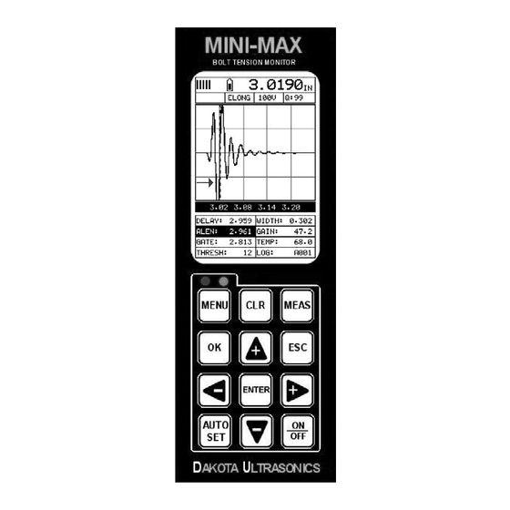
- Page 11 MiniMax Bolt Tension Monitor C. Temperature – Indicates the current temperature of either the temperature sensor, or manual value entered. D. Feature Status Bar – Indicates the features currently enabled and in use: Alarm Quantity Pulser Voltage ...
-
Page 12: Tabbed & Hot Menu Reference
Dakota Ultrasonics 2.4 Tabbed & Hot Menu Reference The following table is a quick menu reference guide of the tabbed menu items, which can be accessed by pressing the key multiple times to tab right, or the multiple times to tab left through the tabbed menus. The MiniMax has 11 tabbed menu titles and multiple submenu items as illustrated below. - Page 13 MiniMax Bolt Tension Monitor >> End DATA UTILS XFER TEMP MODE UPGRADE GAUGE EDIT ALARM CAPTURE TO FILE OPEN ALARM LOW ABOUT CLOSE ALARM HIGH DELETE ONE KEY CLICK FILE DELETE ALL SET DATE DATA SHOW DATE SUMMARY...
-
Page 14: Chapter Three Quick Start Guide
CHAPTER THREE QUICK START GUIDE 3.1 Overview This section demonstrates the basic procedures for setting up and measuring bolts using the MiniMax. More in depth explanations pertaining to the individual functions and features can be found in the chapters that follow. Here we go! 3.2 Getting the MiniMax ready Making all the connections... - Page 15 MiniMax Bolt Tension Monitor 1) Press the key to power up the MiniMax. 2) Press the key once to activate the menu items tab. Press the multiple times to tab right and the key multiple times to tab left until the SETUP menu is highlighted and displaying the submenu items.
- Page 16 Dakota Ultrasonics Note: The default setup, selected in the previous section, automatically defaults to English units – inches. Follow the procedure below to change the units to Metric, if needed. 1) Press the key multiple times to tab right and the...
-
Page 17: Creating A New Group To Store Measurements
MiniMax Bolt Tension Monitor elongation mode, the measurement consists of a difference equation only (Loaded Length – Unloaded Length = Length). Therefore, it doesn’t matter if the ultrasonic length is different from the actual physical length, because the Length will be the same. - Page 18 Dakota Ultrasonics 1) Press the key once to activate the menu items tab. Press the multiple times to tab right, and the key multiple times to tab left, until the DATA menu is highlighted and displaying the submenu items. 2) Press the arrow keys multiple times to scroll through the sub menu items until NEW is highlighted.
- Page 19 MiniMax Bolt Tension Monitor 8) Use the key to backspace if necessary. 9) Repeat steps 6 - 8 until the Group Name is completed. 10) Press the key to save the Group Name and return to the Group List Items menu, or to cancel entering the Group Name.
- Page 20 Dakota Ultrasonics 4) Press the key to select a character and advance to the next field of the Group Note. 5) Use the key to backspace if necessary. 6) Repeat steps 3 - 5 until the Group Note is completed.
- Page 21 MiniMax Bolt Tension Monitor 5) Repeat steps 3 & 4 until the NUM BOLTS value is correctly displayed. 6) Press the key to save the NUM BOLTS and return to the Group List Items menu, or to cancel entering the NUM BOLTS. Note: If a number greater than 250 is entered, an error message box “VALUE IS OUT OF RANGE”...
- Page 22 Dakota Ultrasonics 3) Press the arrow keys multiple times to scroll the highlighted value. 4) Press the arrow keys multiple times to scroll the digit locations. 5) Repeat steps 3 & 4 until the NUM READS value is correctly displayed.
- Page 23 MiniMax Bolt Tension Monitor 1) Press the arrow keys multiple times to scroll through the new Group List Items until START BOLT NUM is highlighted. 2) Press the key to display the Digits Edit Box. 3) Press the arrow keys multiple times to scroll the highlighted value.
- Page 24 Dakota Ultrasonics Selecting the Auto Increment Direction The Auto Increment feature gives the user the ability to specify which direction to advance the cursor after storing a reading. 1) Press the arrow keys multiple times to scroll through the new Group List Items until INCR.
-
Page 25: Setting The Approximate Length
MiniMax Bolt Tension Monitor 1) Press the arrow keys multiple times to scroll through the new Group List Items until CREATE GROUP? is highlighted. 2) Press the key to accept the group parameters, and activate the confirmation screen. 3) Press the key to save the New Group, or the key to cancel the New Group setup and return to the DATA menu. - Page 26 Dakota Ultrasonics 1) Press the key once to activate measure menu items. Press the key multiple times to advance to the next cell right and the key multiple times to advance to the next cell left, until the ALEN cell is highlighted.
- Page 27 MiniMax Bolt Tension Monitor 1) Press the key once to activate the menu items tab. Press the multiple times to tab right, and the key multiple times to tab left, until the AUTO menu is highlighted and displaying the submenu items. 2) Press the arrow keys multiple times to scroll through the sub menu items until APPROX.
-
Page 28: Measuring Reference Lengths
Dakota Ultrasonics 3.6 Measuring Reference Lengths At this point, the MiniMax is setup and ready to start measuring reference lengths. We’ve already setup a bolt group to store the reference length data, and now need to display the group storage locations prior to making measurements. -
Page 29: Measuring Elongations
MiniMax Bolt Tension Monitor moving the transducer to a completely different location on the bolt, thus causing potentially erroneous measurements. Be consistent and as methodical in your methods as possible. This will help to avoid transducer placement errors. 5) Press the key, located in the bottom left corner of the keypad, to locate the detection point, or end of the bolt. - Page 30 Dakota Ultrasonics 1) Press the arrow keys to scroll the target cell cursor to the desired storage location. Note: Elongation values must be stored in column B - ZZ. Note: Do not press the key, while measuring elongation’s, as this activates a high speed mode used specifically with our shut-off box.
-
Page 31: Chapter Four Keyboard, Menu, & Connector Reference
CHAPTER FOUR KEYBOARD, MENU, & CONNECTOR REFERENCE 4.1 Menu Key (Operation & Sub Menus) The Menu key activates the primary menu structure containing 11 menu tab groups. These tab groups then contain sub menu items, or functions. The sub menu items have been organized in tab groups according to how closely they are related to the individual tab group names. - Page 32 Dakota Ultrasonics Activating and Getting Around in the Menu Items 1) Press the key once to activate the menu items tab. Press the multiple times to tab right, and the key multiple times to tab left until the desired tab group is highlighted and displaying the submenu items (A).
-
Page 33: Cal - Menu
MiniMax Bolt Tension Monitor 4.2 CAL – Menu ZERO MODE: The MiniMax is zeroed in much the same way that a mechanical micrometer is zeroed. There are three zero mode options available in the MiniMax – FIXED, ONE POINT, TWO POINT and AUTO. Selecting the proper mode is dependent on the application requirements, but the most convenient mode of preference is - AUTO. -
Page 34: Matl (Material) - Menu
Dakota Ultrasonics 4.3 MATL (material) – Menu UNITS: Toggle between English and Metric units and multiple resolutions for each unit ( IN - .0001, INHR - .00001, or MM - .001, MMHR - .0001 ), Using the abbreviation HR to represent High Resolution. -
Page 35: Disp (Display) - Menu
MiniMax Bolt Tension Monitor vector using the MiniMax or utility software. Alternatively, the load factor can be determined using the bolt calculator in the utility software. However, if extreme accuracy is required, performing a field calibration is a must. This sub menu item enables the user to edit the factor at anytime. -
Page 36: Tune - Menu
Dakota Ultrasonics RECT WAVE: This option provides the user an outlined or filled view option when the display setting is in RECT (rectified) wave mode only. Refer to page 124 for further info. DETECT MARK: Selectable graphics option for the point of detection on the waveform: Line, Box, Dots, None. -
Page 37: Gates - Menu
MiniMax Bolt Tension Monitor 4.7 GATES – Menu POLARITY: The MiniMax operates on a zero crossing detection principal. This feature toggles which stroke of the cycle the crossing detection uses, either positive or negative. Refer to page 156 for further info. GATE: Gates allow the user to view a specific measurement range, or sections of the waveform, and ignore others. -
Page 38: Setup - Menu
Dakota Ultrasonics 4.9 SETUP – Menu OPEN: Displays a list of factory and user defined setups currently stored in memory. These setups can be recalled and used at any time. Refer to page 178 for further info. SAVE: Provides the user with the ability to save a custom setup that has been modified or created by the user. -
Page 39: Util (Utilities) - Menu
MiniMax Bolt Tension Monitor CLOSE: Provides the user the ability to close a currently opened grid or sequential log file. Refer to page 177 for further info. DELETE ONE FILE: This function provides the user with the ability to delete one individual grid or sequential log file from a list of multiple grids/files previously saved in memory. -
Page 40: Xfer (Transfer) - Menu
Refer to page 163 for further info. ABOUT: Provides the user with Dakota Ultrasonics contact information and the MiniMax software version. Refer the Dakota Ultrasonics web site for information on the latest firmware versions available for download. 4.13 CLR (clear) Key The primary functions of the CLR key, are to clear a measurement from a grid or sequential log files cell location or set an obstruct, backspace in an Alpha Edit Box. -
Page 41: Esc Key
MiniMax Bolt Tension Monitor 4.16 ESC Key The ESC key is used in the MENU, MEAS, and EDIT functions as a back or escape key. If the MiniMax is displaying a group file, the OK key toggles the display view options: Digits, RF, RECT views. - Page 42 Dakota Ultrasonics The diagram above is a screenshot of the “Hot Menu” in the MiniMax. The Hot Menu contain all the most regularly adjusted features. The primary purpose of the design was to provide the user with an efficient way to make adjustments on the fly, while continuing to have visibility of the A-Scan display.
-
Page 43: Top & Bottom End Caps
4.22 Top & Bottom End Caps The top & bottom end panels are where all connections are made to the MiniMax. The diagram above shows the layout and description of the connectors: Transducer Connector Refer to Diagram: The transducer connector is a board mounted and shielded LEMO “00”. -
Page 44: Chapter Five Theory Of Operation
The digital signal processor optimizes the measurement process. 5.2 Features of the MiniMax The Dakota Ultrasonics MiniMax, Ultrasonic Bolt Tension Monitor, defines the State of the Art in the measurement of the actual clamp load produced by tightening a fastener. -
Page 45: Ultrasonic Waves
MiniMax Bolt Tension Monitor 5.3 Ultrasonic waves Ultrasonic measurement requires the transmission of a suitable quantity of ultrasonic energy through the length of the bolt. The relationship of the energy pulse frequency to its penetration is important in energy transmission. Lower frequencies produce longer wavelengths that will travel further through a given substance: while higher frequencies produce shorter wavelengths. -
Page 46: Chapter Six Bolt Preparation
CHAPTER SIX BOLT PREPARATION The best balance between maximum frequency and noise suppression requires selecting the best transducer for bolt measurement. The diameter of the transducer (which is generally specified by the diameter of the actual piezoelectric crystal) directly effects energy transmission: Larger diameter crystals have greater ability to send and receive energy, and less of the energy tends to spread laterally. - Page 47 MiniMax Bolt Tension Monitor Figure 1 Sound path in a good bolt Smooth, even surfaced bolt ends that seat the entire active surface of the transducer with minimum gap are required for accurate signal transmission. Bolt ends may need to be cleaned, ground, etc. to achieve the required surface. Avoid: ...
-
Page 48: Bolt End Reflectors
Dakota Ultrasonics Figure 3 Effect of lowered and raised grade marks 6.3 Bolt End Reflectors Smooth, flat reflecting bolt ends that are perpendicular to the axis of the bolt are required for accurate echo reception. Bolt ends may need to be cleaned, ground, etc. - Page 49 MiniMax Bolt Tension Monitor Figure 6 Reflection in a bending bolt...
-
Page 50: Chapter Seven Transducer Selection
CHAPTER SEVEN TRANSDUCER SELECTION 7.1 Selecting the Transducer Transducer selection is a very import part of getting the best results from the MiniMax. The frequency and diameter of transducer should be carefully selected using the following information: Select the largest diameter transducer that will seat completely on the end of the bolt. -
Page 51: Chapter Eight Measuring System Zero (Calibration)
Comparing their known physical length and measured ultrasonic length determines the system delay factor, or zero time offset. The system delay factor makes the Dakota Ultrasonics MiniMax interchangeable with all other calibrated MiniMax systems. Once the delay factor is determined, the MiniMax software automatically subtracts it from the apparent measurement of the time required for the sonic signal to travel through the bolt. -
Page 52: Creating A Group To Document Zero (Calibration) Data
Dakota Ultrasonics The MiniMax should be sent in for calibration by Dakota Ultrasonics, or other authorized service representative, on a periodic basis to verify proper operation of the instrument. Dakota Ultrasonics recommends one-year intervals. Depending on the how critical the application is, bolts should be calibrated in a lab against a known load prior to measuring. - Page 53 MiniMax Bolt Tension Monitor 2) Press the arrow keys multiple times to scroll through the sub menu items until NEW is highlighted. 3) Press the key to display the New Group Edit Box. 4) Press the arrow keys multiple times to scroll through the new Group List Items until NAME is highlighted.
- Page 54 Dakota Ultrasonics Note: Be sure to include a note that describes and references the Zero/Cal data, and or bolt. 1) Press the arrow keys multiple times to scroll through the new Group List Items until NOTE is highlighted. 2) Press the key to activate the Alpha Edit Box.
- Page 55 MiniMax Bolt Tension Monitor 7) Press the key to save the Group Note and return to the Group List Items menu, or to cancel entering the Group Note. Selecting the Number of Bolts in the Group Note: A group can contain up to 250 bolts. In this case, the number of bolts in the group can be thought of as the number of reference points on the calibration standards.
- Page 56 Dakota Ultrasonics 6) Press the key to save the NUM BOLTS and return to the Group List Items menu, or to cancel entering the NUM BOLTS. 7) Press the key to display the Digits Edit Box and re-enter the NUM BOLTS.
- Page 57 MiniMax Bolt Tension Monitor 4) Press the arrow keys multiple times to scroll the digit locations. 5) Repeat steps 3 & 4 until the NUM READS value is correctly displayed. 6) Press the key to save the NUM READS and return to the Group List Items menu, or to cancel entering the NUM READS.
- Page 58 Dakota Ultrasonics 1) Press the arrow keys multiple times to scroll through the new Group List Items until START BOLT NUM is highlighted. 2) Press the key to display the Digits Edit Box. 3) Press the arrow keys multiple times to scroll the highlighted value.
- Page 59 MiniMax Bolt Tension Monitor The Auto Increment feature gives the user the ability to specify which direction to advance the cursor after storing a reading. 1) Use the arrow keys to scroll through the new Group List Items until INCR. DIR is highlighted. 2) Use the arrow keys to toggle the Increment direction NONE, NORTH, EAST, SOUTH, or WEST.
-
Page 60: Auto Zero/Calibration
Dakota Ultrasonics 1) Press the arrow keys multiple times to scroll through the new Group List Items until CREATE NEW GROUP? is highlighted. 2) Press the key to accept the group parameters, and activate the confirmation screen. 3) Press the... - Page 61 MiniMax Bolt Tension Monitor 1) Press the key multiple times to tab right and the key multiple times to tab left until the CAL menu is highlighted and displaying the submenu items. 2) Press the arrow keys multiple times to scroll through the sub menu items until ZERO MODE is highlighted.
- Page 62 Dakota Ultrasonics 5) Press the key to display the AUTO list box. 6) Press the arrow keys multiple times to scroll through the AUTO list until PHY LENGTH is highlighted. Note: PHY LENGTH is the actual physical length of the calibration standard.
- Page 63 Note: The TEMP COEF should be set to 55 (99 Metric) for the 3 & 6” bars supplied by Dakota Ultrasonics. If the glass block is used, it should be set to 0. The reason for this is because glass has a very low temperature coefficient.
- Page 64 Dakota Ultrasonics 21) Press the arrow keys multiple times to scroll the hot menu items until ACCEPT CAL is highlighted. 22) Press the key to accept the calibration and return to the AUTO list, or to cancel the calibration. 23) Press the arrow keys multiple times to scroll through the AUTO list until CALC ZERO is highlighted.
- Page 65 MiniMax Bolt Tension Monitor 25) Press the key multiple times to tab right and the key multiple times to tab left until the MATL menu is highlighted and displaying the submenu items. 26) Press the arrow keys multiple times to scroll through the sub menu items until VELOCITY is highlighted.
-
Page 66: Using A Standard Bolt
Dakota Ultrasonics 35) Press the key to display the CAL DATA group. 36) Press the arrow keys to scroll the target cell cursor to the desired storage location. Note: The first column A must be used to store reference lengths. - Page 67 MiniMax Bolt Tension Monitor 1) Press the key once to activate the menu items tab. Press the multiple times to tab right and the key multiple times to tab left until the MATL menu is highlighted and displaying the submenu items. 2) Press the arrow keys multiple times to scroll through the sub menu items until TYPE is highlighted.
- Page 68 Dakota Ultrasonics obtaining the information needed to use the standard bolt for a probe zero calibration bar. Setting up a Bolt Standard – For the First Time 1) With the menu items already active, press the key multiple times to tab...
- Page 69 MiniMax Bolt Tension Monitor 5) Press the arrow keys multiple times to scroll through the sub menu items until TYPE is highlighted. Press the key to display the list of bolt types. 7) Press the arrow keys multiple times to scroll through the bolt material types until the appropriate bolt type is highlighted.
- Page 70 Dakota Ultrasonics 11) Press the key multiple times to tab right and the key multiple times to tab left until the GEOM menu is highlighted and displaying the submenu items. 12) Press the arrow keys multiple times to scroll through the sub menu items until QUANTITY is highlighted.
- Page 71 MiniMax Bolt Tension Monitor 17) Press the arrow keys multiple times to scroll the highlighted value. 18) Press the arrow keys multiple times to scroll the digit locations. 19) Repeat steps 17 & 18 until the APPROX LEN value is correctly displayed. 20) Press the key to set the Approximate Length and return to the menu screen, or...
- Page 72 Dakota Ultrasonics 23) Press the key and the Ultrasonic Length of the bolt will be displayed and should be documented and scribed on the bolt, along with the Velocity and Temperature Coefficient, for future zero verification. 24) Proceed to the next section to save this length in the zero group CAL DATA created in a previous section.
- Page 73 MiniMax Bolt Tension Monitor 6) Proceed to the next section to perform and store the first Probe Zero verification. DO NOT REMOVE THE TRANSDUCER FROM THE BOLT. The next two sections outline the procedures of how to perform a probe zero calibration by calculating a zero value, or alternatively adjusting the temperature value to match the existing probe zero value.
- Page 74 Dakota Ultrasonics 2) Press the arrow keys multiple times to scroll through the sub menu items until ZERO MODE is highlighted. 3) Press the arrow keys multiple times to scroll the zero mode options until ONE POINT is displayed. Note: Each time the arrow keys are pressed a confirmation screen will appear to warn the user that the zero mode is being changed.
- Page 75 MiniMax Bolt Tension Monitor Note: Enter the known ultrasonic length of the bolt that was documented and stored in the previous section. We will consider this ultrasonic length to be the actual physical length from this point forward. Reminder: It was stored in the first column of the probe zero group.
- Page 76 Dakota Ultrasonics 14) Press the arrow keys multiple times to scroll the highlighted value. 15) Press the arrow keys multiple times to scroll the digit locations. 16) Repeat steps 14 & 15 until the VELOCITY value is correctly displayed. 17) Press the...
- Page 77 MiniMax Bolt Tension Monitor 22) Repeat steps 20 & 21 until the TEMP COEF value is correctly displayed. 23) Press the key to return to the One Point Zero List, or to cancel entering the TEMP COEF value. 24) Press the arrow keys multiple times to scroll through the One Point Zero List Items until ULTRASONIC 1 is highlighted.
- Page 78 Dakota Ultrasonics 30) Press the key to calculate, change, and display the new velocity and zero values, or to cancel the calibration. Note: If was pressed to calculate the new values, pressing the once will display the CAL menu items to review the new ZERO value calculated.
- Page 79 MiniMax Bolt Tension Monitor Note: User has selected this section because the MiniMax, transducer, or transducer cable has not changed and the elongation is outside the tolerance of +/- .0005”. Note: This section assumes that a group CAL DATA has been created and opened/active, as outlined in section 8.3.
-
Page 80: Calibration / Zero Bars & Triple Sided Glass Block
Dakota Ultrasonics 6) Press the arrow keys multiple times to scroll the TEMP value. 7) Continue to scroll the temp value until the elongation reads 0.0000. When the value is at 0.0000 the MiniMax is officially zeroed and ready to store or document the zero data prior to making measurements. - Page 81 MiniMax Bolt Tension Monitor procedures in the next section demonstrate a Two-Point calibration. However, the same procedures apply to the One-Point calibration option also. The user would simply follow the same procedures and ignore references to the second point. Measuring Calibration Standards – For the First Time Note: It is assumed that the temperature sensor is connected to the MiniMax, and semi automatic or automatic mode has been selected.
- Page 82 Dakota Ultrasonics Note: The two-point option allows the user to use two separate points for the probe zero calibration. Note: The one point option can optionally be selected if only one cal bar will be used. Although the procedures below are described with the two-point option in mind, they will also work in the case of a one-point calibration.
- Page 83 MiniMax Bolt Tension Monitor 7) Press the key to display the Digits Edit Box. 8) Press the arrow keys multiple times to scroll the highlighted value. 9) Press the arrow keys multiple times to scroll the digit locations. 10) Repeat steps 8 & 9 until the PHY LEN 1 value is correctly displayed. 11) Press the key to return to the Two Point Zero list, or to cancel...
- Page 84 Dakota Ultrasonics 16) Repeat steps 14 & 15 until the PHY LEN 2 value is correctly displayed. 17) Press the key to return to the Two Point Zero list, or to cancel entering the PHY LEN 2. 18) Press the arrow keys to scroll through the Two Point Zero list until VELOCITY is highlighted.
- Page 85 Note: This should be set to 55 (99 Metric) for the 3 & 6” bars supplied by Dakota Ultrasonics. If the glass block is used, it should be set to 0. The reason for this is because glass has a very low temperature coefficient.
- Page 86 Dakota Ultrasonics 31) Press the arrow keys multiple times to scroll AUTO, POSITIVE or NEGATIVE polarity options. 32) Press the key once to leave the Two Point Zero list. 33) Press the key multiple times to tab right and the...
- Page 87 MiniMax Bolt Tension Monitor 39) Press the key to return to the MATL menu, or to cancel entering the VELOCITY. 40) Repeat steps 34 – 37 to enter the TEMP COEF. 41) Repeat steps 34 – 37 to enter the STRESS FACTOR as 1.000”. 42) Proceed to the next section.
- Page 88 Dakota Ultrasonics 2) Press the arrow keys multiple times to scroll through the sub menu items until QUANTITY is highlighted. 3) Press the arrow keys multiple times to scroll the quantity options until the ELONG option is displayed. Note: This will set the quantity display in terms of elongation.
- Page 89 MiniMax Bolt Tension Monitor 6) Press the key to display the list of log files. 7) Press the arrow keys multiple times to scroll through the log names until CAL DATA is highlighted. 8) Press the key to open the log, followed by pressing the to confirm “load from memory”, or to cancel opening the log file.
- Page 90 Dakota Ultrasonics 12) Press the arrow keys multiple times to scroll through the sub menu items until ULTRASONIC 1 is highlighted. 13) Apply a drop of couplant to the standard or transducer and attach it to one end of the 3” calibration bar.
- Page 91 MiniMax Bolt Tension Monitor 20) Press the key to display the measurement screen. Note: Rotate the transducer clockwise and counter clockwise applying a small amount of pressure to eliminate any excess couplant between the transducer and cal bar surface. 21) Press the key to automatically setup and measure the 6”...
- Page 92 Dakota Ultrasonics 31) Press the arrow keys multiple times to scroll the highlighted value. 32) Press the arrow keys multiple times to scroll the digit locations. 33) Repeat steps 31 & 32 until the VELOCITY value is correctly displayed. 34) Press the key once to activate measure menu items.
- Page 93 MiniMax Bolt Tension Monitor 41) Apply a drop of couplant to the cal bar or transducer and attach it to one end of the 3” calibration bar. Make sure it is in the original position when the measurement was first taken. 42) Press the key to display the measurement screen.
- Page 94 Dakota Ultrasonics If we consider the initial probe zero value constant, as the hardware cal bars or glass block have not been replaced, the future verifications should always show an elongation value of +/- 0.0005”, in order to be considered “In Spec”. If the probe zero/cal is out of spec, the user should redo the zero/cal procedure in its entirety.
- Page 95 MiniMax Bolt Tension Monitor 4) Press the arrow keys multiple times to scroll through the list menu items until the group name containing the probe zero data CAL DATA is highlighted. 5) Press the key to load the zero data group into memory, followed by pressing the key to confirm loading the group into memory.
- Page 96 Dakota Ultrasonics column B. It’s also important to note that the L-REF stored in column A, also contains all the MiniMax settings when the L-REF was initially measured. These settings will automatically be copied to all the columns B-ZZ, for each individual bolt.
-
Page 97: Chapter Nine Temperature Compensation
CHAPTER NINE TEMPERATURE COMPENSATION 9.1 Purpose The temperature of a fastener affects the overall physical length, as well as the velocity of a fastener. As the temperature of a fastener increases, the ultrasonic length increases at a rate greater than the physical change in length. If the user intends to measure the same fastener at different time intervals over the service life of the bolt, temperature compensation is very important to produce accurate results. -
Page 98: Semi Automatic Mode
Dakota Ultrasonics 2) Press the arrow keys multiple times to scroll through the sub menu items until TEMP MODE is highlighted. 3) Press the arrow keys multiple times to scroll the temperature mode options. Once the MANUAL temperature mode is displayed, press key to return to the measurement screen. - Page 99 MiniMax Bolt Tension Monitor automatically changing. Some companies and application procedures may call for manually initiating and physically viewing the change in temperature by adding a manual step to the procedures. The semi automatic mode answers requirements such as these. Selecting Semi Automatic Temperature Mode 1) Press the key once to activate the menu items tab.
-
Page 100: Automatic Mode
Dakota Ultrasonics 9.4 Automatic Mode The automatic mode constantly monitors and compensates for temperature when the accessory temperature sensor is attached to the MiniMax and placed on the joint or fastener being measured. While this mode eliminates the need to manually insert or... -
Page 101: Chapter Ten Bolt Material Calibration
CHAPTER TEN BOLT MATERIAL CALIBRATION 10.1 Why Calibrate? The preset bolt types in the MiniMax contain average factors for the material type. These are approximate values only. In a tightly controlled application where extreme accuracy is required, it is necessary to obtain all the information possible about the fasteners being measured. - Page 102 Dakota Ultrasonics 3) Press the arrow keys multiple times to scroll the quantity until ELONG is displayed. 4) Press the key multiple times to tab right, and the key multiple times to tab left, until the MATL menu is highlighted and displaying the submenu items.
- Page 103 MiniMax Bolt Tension Monitor 10) Press the key multiple times to tab right, and the key multiple times to tab left, until the AUTO menu is highlighted and displaying the submenu items. 11) Press the arrow keys multiple times to scroll through the sub menu items until APPROX LEN is highlighted.
- Page 104 Dakota Ultrasonics 18) Apply a drop of couplant to the bolt or transducer, and attach it to one end of the bolt. Rotate the transducer clockwise and counter clockwise applying a small amount of pressure to eliminate any excess couplant between the transducer and bolt surface.
-
Page 105: Stress Factor Calibration
MiniMax Bolt Tension Monitor 22) Press the arrow keys multiple times to scroll through the sub menu items until VELOCITY is highlighted. 23) Press the key to display the Digits Edit Box. Note: Enter the Correct Velocity calculated above. 24) Press the arrow keys multiple times to scroll the highlighted value. - Page 106 Sonic Stress Factor is to be determined. NOTES: The Dakota Ultrasonics MiniMax must be calibrated, or zeroed, as described in the Zero Calibration procedure section 8.6. The Velocity Calibration should be performed prior to determining the Stress Factor.
- Page 107 MiniMax Bolt Tension Monitor MECHANICAL SonicStressFactor ULTRASONIC UltrasonicLength ZeroLoad MechanicalLength ZeroLoad UltrasonicLength Load MechanicalLength Load Calibrating the Stress Factor 1) Using the mechanical measuring device, measure and record the Mechanical Length at Zero Load “L ”...
- Page 108 Dakota Ultrasonics working conditions. Using the mechanical measuring device, measure and record the Mechanical Length at Load 1 “ L ” for the current sample bolt. 6) Apply a drop of couplant to the bolt or transducer, and attach it to one end of the bolt.
-
Page 109: Temperature Factor Calibration
108 F depending on water purity and atmospheric pressure. By measuring the temperature of the stirred water bath with a precise mercury thermometer, while reading the ultrasonic length of the bolt, accurate calibration points can be obtained. A Dakota Ultrasonics MiniMax Ultrasonic Bolt Tension Monitor. - Page 110 Temperature Factor is to be determined. NOTES: The Dakota Ultrasonics MiniMax must be calibrated, or zeroed, as described in the procedure entitled Measuring System Zero in 8.1. The sample bolts should be left to soak at the measured temperature points for a period of not less than 20 minutes, to insure that temperature is uniform throughout the sample.
- Page 111 MiniMax Bolt Tension Monitor transducer and bolt. Be sure to always place the transducer in the same location. This will help to eliminate any potential measurement errors caused by changing the sound path. 3) Record the ultrasonic length “L ” of the sample bolt at the above minimum temperature - 48 4) Repeat step 1 - 3 at the target temperatures (T through T...
-
Page 112: Chapter Eleven Load Measurment
CHAPTER ELEVEN LOAD MEASURMENT 11.1 Calculating Load Factor The load factor is an empirically determined value for the geometry of the bolt. It is the amount of load required to elongate the bolt 0.001” in English Units or 0.01mm in Metric Units. - Page 113 MiniMax Bolt Tension Monitor For bolts with complex geometry, the areas should be estimated by averaging each individual area and length. In the case of a hollow fastener, the area of the hole must be subtracted from the overall area. The area of a fastener with complex geometry can be estimated as follows: ...
-
Page 114: Calibrating Load Factor (Field Calibration)
Dakota Ultrasonics C LA M P LE N G T H 1 /2 TH E D IA M E TE R 1 /3 T H E D IA M E TE R E FFE C T IV E LE N G T H... -
Page 115: Performing A Field Calibration
MiniMax Bolt Tension Monitor zero and produces only a load factor. Why are both options needed? In applications where a small amount of load is applied to the fastener, thus producing very little elongation, the regression option can potentially produce non-linear results. In cases such as these, a vector may sometimes produce better results as the offset is set at zero. - Page 116 Dakota Ultrasonics Note: Select a name that references this group to Field Calibration Data. 1) Press the key once to activate the menu items tab. Press the multiple times to tab right, and the key multiple times to tab left, until the DATA menu is highlighted and displaying the submenu items.
- Page 117 MiniMax Bolt Tension Monitor 6) Press the arrow keys to scroll to highlight the appropriate alpha characters. 7) Press the key to select a character and advance to the next field of the Group Name. 8) Use the key to backspace if necessary. 9) Repeat steps 6 - 8 until the Group Name is completed.
- Page 118 Dakota Ultrasonics 1) Press the arrow keys multiple times to scroll through the new Group List Items until NOTE is highlighted. 2) Press the key to activate the Alpha Edit Box. 3) Press the arrow keys to scroll to highlight the appropriate alpha characters.
- Page 119 MiniMax Bolt Tension Monitor 1) Press the arrow keys multiple times to scroll through the new Group List Items until NUM BOLTS is highlighted. 2) Press the key to display the Digits Edit Box. 3) Press the arrow keys multiple times to scroll the highlighted value.
- Page 120 Dakota Ultrasonics 1) Press the arrow keys multiple times to scroll through the new Group List Items until NUM READS is highlighted. 2) Press the key to display the Digits Edit Box. 3) Press the arrow keys multiple times to scroll the highlighted value.
- Page 121 MiniMax Bolt Tension Monitor Selecting the Starting Bolt Number Note: Depending on the application and layout of the project, the user won’t always want the starting bolt to be 1. This feature allows the user to define what the starting number will be. 1) Press the arrow keys multiple times to scroll through the new Group List Items until START BOLT NUM is highlighted.
- Page 122 Dakota Ultrasonics Note: If a value is enter that is greater than the maximum number of bolts allowed per group (250), an error message box “VALUE IS OUT OF RANGE” will be displayed. 7) Press the key to display the Digits Edit Box and re-enter the START BOLT NUM.
- Page 123 MiniMax Bolt Tension Monitor Saving the Group Once all the parameters are set, the user has the option of saving or canceling the new group. 1) Press the arrow keys multiple times to scroll through the new Group List Items until CREATE NEW GROUP? is highlighted. 2) Press the key to accept the group parameters, and activate the confirmation screen.
- Page 124 Dakota Ultrasonics Storing the Reference Length 1) Press the key once to activate measure menu items. Press the key multiple times to move right and the key multiple times to move left until the LOG cell is highlighted. 2) Press the key to display the Group View Box.
- Page 125 MiniMax Bolt Tension Monitor 2) Press the arrow keys multiple times to scroll through the sub menu items until LOAD CAL MODE is highlighted. 3) Press the arrow keys multiple times to scroll through the unit options OFF, VECTOR (zero offset), REGRESSION, until the correct mode is displayed.
- Page 126 Dakota Ultrasonics 4) Apply approximately 1/3 of the maximum load, which is to be placed on the bolt under actual working conditions. 5) Measure and record the Ultrasonic Length at Load 1 by pressing the key. The Digits Edit Box will be displayed.
- Page 127 MiniMax Bolt Tension Monitor 15) Press the key to store the Known Load and return to the measurement screen, or to cancel entering the Known Load. 16) Increase the applied load to approximately the maximum load, which is to be placed on the bolt under actual working conditions. 17) Measure and record the Ultrasonic Length at Load 3 by pressing the key.
- Page 128 Dakota Ultrasonics 2) Press the arrow keys multiple times to scroll through the sub menu items until LOAD CAL CALC is highlighted. 3) Press the key to run the calculation and display the confirmation screen. Note: The regression or vector coefficient will be displayed. The closer this number is to 1, the better the fit, or least amount of error.
-
Page 129: Chapter Twelve Measurement & Waveform Display
CHAPTER TWELVE MEASUREMENT & WAVEFORM DISPLAY 12.1 Quantities of Measurement The MiniMax has the ability to measure in a number of measurement quantities: Time (nanoseconds), Elongation, Load, Stress, and Strain (in terms of %). While there are a number of quantity options available, the easiest and most fail safe quantities to consider are Time and Elongation. -
Page 130: Display View Options
Dakota Ultrasonics 12.2 Display View Options A key feature of the MiniMax is the versatility of the display views available to the user. The waveform views are a graphical representation of the actual sound reflections traveling through a fastener and returning back to the transducer. The waveform display shows the amplitude of the signal received on the vertical (Y) axis and time (displayed in terms of length) on the horizontal (X) axis. - Page 131 MiniMax Bolt Tension Monitor Digits Hot Menus RF Hot Menus Changing Display Options 1) Press the key once to activate the menu items tab. Press the multiple times to tab right, and the key multiple times to tab left, until the DISP menu is highlighted and displaying the submenu items.
- Page 132 Dakota Ultrasonics The RF mode shows the waveform in a similar fashion to an oscilloscope. It shows both the positive and the negative peaks. The peak (either positive or negative) selected for measurement is shown in upper portion of the display.
- Page 133 MiniMax Bolt Tension Monitor C. Temperature – Indicates the current temperature of either the temperature sensor, or manual value entered. D. Feature Status Bar – Indicates the features currently enabled and in use: Alarm Quantity Pulser Voltage ...
-
Page 134: Adjusting The Display
Dakota Ultrasonics 12.3 Adjusting the Display The width refers to the overall viewable range, with respect to length, being displayed on the screen. The starting length is displayed at the lower left side of the screen, and the ending length is shown at the lower right hand side of the screen. The difference between these values is called the Width. - Page 135 MiniMax Bolt Tension Monitor Adjusting the Width using the Tabbed Menus 1) Press the key once to activate the menu items tab. Press the multiple times to tab right, and the key multiple times to tab left, until the DISP menu is highlighted and displaying the submenu items. 2) Press the arrow keys multiple times to scroll through the sub menu items until WIDTH is highlighted.
- Page 136 Dakota Ultrasonics Starting delay The starting DELAY, or starting length, is the value displayed on the bottom lower left side of the display in both RF and RECT (Rectified) views. Note: Once the range is set, it will remain the same for all the views respectively.
- Page 137 MiniMax Bolt Tension Monitor 1) Press the key once to activate the menu items tab. Press the multiple times to tab right, and the key multiple times to tab left, until the DISP menu is highlighted and displaying the submenu items. 2) Press the arrow keys multiple times to scroll through the sub menu items until DELAY is highlighted.
-
Page 138: Gain
Dakota Ultrasonics 12.4 Gain The gain, or amplification of the return echoes, can be adjusted over a wide range. The setting of the gain is crucial in order to obtain valid readings during the measurement process. Too much gain may result in erroneous measurements, by detecting on noise rather than the length of the fastener itself. - Page 139 MiniMax Bolt Tension Monitor The user can also access and adjust the gain from the tabbed menus. However, this method is more tedious than making the adjustments using the hot menu. The procedure using the tabbed menus is outlined below: Adjusting the Gain using the Tabbed Menus 1) Press the key once to activate the menu items tab.
- Page 140 Dakota Ultrasonics 5) Press the arrow keys multiple times to scroll the highlighted value. 6) Press the arrow keys multiple times to scroll the digit locations. 7) Repeat steps 5 & 6 until the GAIN value is correctly displayed. 8) Press the key to set the GAIN and return to the menu screen, or to cancel entering the GAIN.
-
Page 141: Gate
MiniMax Bolt Tension Monitor 3) Press the arrow keys multiple times to scroll the value. When the correct Step Size is being displayed, proceed to step 8. 4) Alternatively, press the key to display the Digits Edit Box. 5) Press the arrow keys multiple times to scroll the highlighted value. - Page 142 Dakota Ultrasonics bolt, and resulting in a return echo slightly longer than the overall length of the bolt. A detection can only occur inside of the boundaries of the gate. Therefore, setting the start of the gate beyond the first reflection from the end of the bolt will force the MiniMax to look for the next detection.
- Page 143 MiniMax Bolt Tension Monitor 1) Press the key once to activate measure menu items. Press the key multiple times to move right and the key multiple times to move left until the GATE cell is highlighted. 2) Press the arrow keys multiple times to scroll the highlighted value.
-
Page 144: Threshold
Dakota Ultrasonics 1) Press the key once to activate the menu items tab. Press the multiple times to tab right and the key multiple times to tab left until the AUTO menu is highlighted and displaying the submenu items. 2) Press the arrow keys multiple times to scroll through the sub menu items until GATE is highlighted. - Page 145 MiniMax Bolt Tension Monitor The procedures to adjust the Thresholds are outlined below: Adjusting the Thresholds using the Hot Menus 1) Press the key once to activate measure menu items. Press the key multiple times to move right and the key multiple times to move left, until the desired Threshold cell is highlighted.
- Page 146 Dakota Ultrasonics 1) Press the key once to activate the menu items tab. Press the multiple times to tab right, and the key multiple times to tab left, until the GATES menu is highlighted and displaying the submenu items. 2) Press the arrow keys multiple times to scroll through the sub menu items until Threshold is highlighted.
-
Page 147: Interpreting The Waveform
MiniMax Bolt Tension Monitor 12.7 Interpreting the Waveform One of the most important things to consider, when using the MiniMax, is how to interpret the waveform in order to choose the proper phase (polarity) and gain setting. It’s also important to understand what’s taking place during a basic measurement. -
Page 148: Manually Locating The Echo
Dakota Ultrasonics zero crossing of the positive first cycle W1+. In this example, the correct (positive) polarity has been selected. Why? I’m getting to that! Refer to Fig.2. Notice that when the bolt is tightened, the signal amplitude has decreased due to the applied stress, and a peak jump has occurred from W1- to W2- at (B). - Page 149 MiniMax Bolt Tension Monitor 1) Press the key once to activate measure menu items. Press the key multiple times to move right and the key multiple times to move left, until the DELAY cell is highlighted. 2) Press the arrow keys multiple times to scroll the highlighted value.
-
Page 150: Automatic Echo Optimization (Auto Set)
Dakota Ultrasonics 3) Alternatively, press the key to display the Digits Edit Box. 4) Press the arrow keys multiple times to scroll the highlighted value. 5) Press the arrow keys multiple times to scroll the digit locations. 6) Repeat steps 4 & 5 until the WIDTH value is correctly displayed. - Page 151 MiniMax Bolt Tension Monitor 1) Press the key once to activate measure menu items. Press the key multiple times to move right and the key multiple times to move left, until the ALEN cell is highlighted. 2) Press the key to display the Digits Edit Box. 3) Press the arrow keys multiple times to scroll the highlighted value.
- Page 152 Dakota Ultrasonics 2) Press the arrow keys multiple times to scroll through the sub menu items until APPROX. LEN. is highlighted. 3) Press the key to display the Digits Edit Box. 4) Press the arrow keys multiple times to scroll the highlighted value.
-
Page 153: Unloaded Length And Elongation Measurements
MiniMax Bolt Tension Monitor 1) Press the key once to activate the menu items tab. Press the multiple times to tab right, and the key multiple times to tab left, until the UTIL menu is highlighted and displaying the submenu items. 2) Press the arrow keys multiple times to scroll through the sub menu items until AUTO SET is highlighted. -
Page 154: Chapter Thirteen Additional Features
CHAPTER THIRTEEN ADDITIONAL FEATURES 13.1 Quality/Correlation (Transducer Placement) The auto correlation feature in the MiniMax is a handy feature to assist the user with returning the transducer back to the original position/location where it was during the initial reference length measurement. Since the sound path is changing, in terms of material consistency, returning the transducer to the same location increases the accuracy of the MiniMax, reducing what is referred to as the “placement error”. -
Page 155: Backlight
MiniMax Bolt Tension Monitor Adjusting Contrast 1) Press the key once to activate the menu items tab. Press the multiple times to tab right and the key multiple times to tab left until the DISP menu is highlighted and displaying the submenu items. 2) Press the arrow keys multiple times to scroll through the sub menu items until CONTRAST is highlighted. -
Page 156: Graphics Options (Look & Feel)
Dakota Ultrasonics 1) Press the key once to activate the menu items tab. Press the multiple times to tab right and the key multiple times to tab left until the DISP menu is highlighted and displaying the submenu items. 2) Press the arrow keys multiple times to scroll through the sub menu items until BACKLIGHT is highlighted. - Page 157 MiniMax Bolt Tension Monitor Filled – Draws a filled version of the waveform. Detect Mark: The detect mark is another look and feel option for displaying the detection indicator.
-
Page 158: Pulse
Dakota Ultrasonics 13.5 Pulse The MiniMax has a 200 volt square wave pulser. Pulse width, refers to the duration of time the pulser is left on. This time results in increased energy sent into the fastener. There are three pulse width options (SPIKE, THIN, and WIDE), with adjustable pulser voltages of 100, 150 and 200 volts. -
Page 159: Pulser Voltage
MiniMax Bolt Tension Monitor 1) Press the key once to activate the menu items tab. Press the multiple times to tab right and the key multiple times to tab left until the TUNE menu is highlighted and displaying the submenu items. 2) Use the arrow keys multiple times to scroll through the sub menu items until PULSE is highlighted. -
Page 160: Damping
Dakota Ultrasonics 1) Press the key once to activate the menu items tab. Press the multiple times to tab right and the key multiple times to tab left until the TUNE menu is highlighted and displaying the submenu items. 2) Use the arrow keys multiple times to scroll through the sub menu items until PULSER VOLTAGE is highlighted. -
Page 161: Digitizer
MiniMax Bolt Tension Monitor 1) Press the key once to activate the menu items tab. Press the multiple times to tab right, and the key multiple times to tab left, until the TUNE menu is highlighted and displaying the submenu items. 2) Use the arrow keys multiple times to scroll through the sub menu items until DAMPING is highlighted. -
Page 162: Polarity
Dakota Ultrasonics 1) Press the key once to activate the menu items tab. Press the multiple times to tab right and the key multiple times to tab left until the TUNE menu is highlighted and displaying the submenu items. 2) Use the arrow keys multiple times to scroll through the sub menu items until DIGITIZER is highlighted. -
Page 163: Alarm Mode
MiniMax Bolt Tension Monitor Note: Before toggling the Polarity, the MiniMax should be set to the RF display view option. The RF view will give the user the best opportunity to correctly view the positive and negative cycles of the waveform. Please refer section 12.2 for information on selecting the Display Views. - Page 164 Dakota Ultrasonics Note: The alarm feature can also be used in conjunction with an accessory high speed shutoff box that is wired into the power of the pump and will shutdown the pump when inside of the alarm limit values.
- Page 165 MiniMax Bolt Tension Monitor 1) Assuming the ALARM is ON, press the arrow keys multiple times to scroll through the sub menu items until ALARM LOW is highlighted. 2) Press the key to display the Digits Edit Box. 3) Press the arrow keys multiple times to scroll the highlighted value.
-
Page 166: Key Click
Dakota Ultrasonics 13.11 Key Click When a key is pressed on the MiniMax keypad, the user can control whether or not an audible beep is sounded and at what volume level, if any. The procedure for this feature/preference is outlined below:... - Page 167 MiniMax Bolt Tension Monitor 1) Press the key once to activate the menu items tab. Press the multiple times to tab right and the key multiple times to tab left until the UTIL menu is highlighted and displaying the submenu items. 2) Use the arrow keys multiple times to scroll through the sub menu items until SET DATE is highlighted.
-
Page 168: Upgrade Gauge
Dakota Ultrasonics 8) Finally, press the key to return to the measurement screen and begin taking readings. 13.13 Upgrade Gauge The MiniMax can be upgraded very conveniently at your desk or in the field. The latest version of firmware can be found on the Dakota website, which can be compared to the current version loaded in the MiniMax. -
Page 169: Freeze & Capture
MiniMax Bolt Tension Monitor 4) Press the key to start the upgrade process. Note: The gauge will power itself off, and start upgrading indicated by the red & green alarm lights periodically flashing. When the upgrade is completed, the lights will stop flashing. DO NOT LOSE POWER! Be sure the MiniMax has plenty of battery life prior to upgrading, or the gauge is powered via PC or AC adaptor. - Page 170 Dakota Ultrasonics 2) Use the arrow keys multiple times to scroll through the sub menu items until CAPTURE TO FILE is highlighted. 3) Use the arrow keys to toggle the CAPTURE on/off. Note: Capture will be displayed in a toolbar cell on the active display, indicating the feature is enabled.
-
Page 171: Chapter Fourteen Data Storage - Setup, Edit, & View Files
CHAPTER FOURTEEN DATA STORAGE – SETUP, EDIT, & VIEW FILES 14.1 Introduction to Group (spreadsheet) format Data is stored in the MiniMax in a spreadsheet like format called a GRID. A GRID is simply a two dimensional table of readings. In the case of the MiniMax we’ll refer to a GRID as a GROUP. - Page 172 Dakota Ultrasonics This process can be repeated for the name, note, number of bolts, number of reads, starting bolt number, and the increment direction using the procedure below: Creating a Group 1) Press the key once to activate the menu items tab. Press the...
- Page 173 MiniMax Bolt Tension Monitor 5) Press the key to activate the Alpha Edit Box. 6) Press the arrow keys to highlight the appropriate alpha/numeric characters. 7) Press the key to select a character and advance to the next field. Note: Use the key to backspace if necessary.
-
Page 174: Storing A Reading
Dakota Ultrasonics 1) Press the arrow keys multiple times to scroll through the new Group List Items until CREAT GRID is highlighted. 2) Press the key to display CREATE GRID confirmation screen. 3) Press the key to save the group and return to the measurement screen. -
Page 175: Viewing Stored Readings
MiniMax Bolt Tension Monitor correctly displayed, press the key to advance directly to that row number in the group. Key Feature: When the is displaying a “group”, pressing the MiniMax key multiple times will toggle through the display options: DIGITS, RF, and RECT views. -
Page 176: Deleting Groups (Files)
Dakota Ultrasonics 1) Press the key once to activate measure menu items. Press the key multiple times to move right and the key multiple times to move left until the LOG cell is highlighted. 2) Press the key to display the Grid Log Box. - Page 177 MiniMax Bolt Tension Monitor Deleting One or All Files from Memory Deleting One File 1) Press the key once to activate the menu items tab. Press the multiple times to tab right and the key multiple times to tab left until the DATA menu is highlighted and displaying the submenu items.
- Page 178 Dakota Ultrasonics 6) Press the key to return to the measurement screen. Deleting All Data 1) Press the key once to activate the menu items tab. Press the multiple times to tab right and the key multiple times to tab left until the DATA menu is highlighted and displaying the submenu items.
-
Page 179: Editing A Group (File)
MiniMax Bolt Tension Monitor 14.6 Editing a Group (File) Once a grid has been created and saved to memory, the user can edit the Name, Comments, or Increment Direction at a later time. The following procedures outline this process: Editing a Grid 1) Press the key once to activate the menu items tab. - Page 180 Dakota Ultrasonics 5) Press the key to activate the Alpha Edit box – Only used when editing the NOTE. 6) Use the arrow keys to highlight the appropriate alpha characters. 7) Press the key to select a character and advance to the next field of the Comments.
-
Page 181: Changing The Active File - Open
MiniMax Bolt Tension Monitor 11) Press the key to save the changes or the key to cancel editing the file parameters. 12) Press the key to return to the measurement screen. 14.7 Changing the active File - Open The user may have transferred grid/seq templates from a PC to the MiniMax, or setup grids/seq using the MiniMax at an earlier time. - Page 182 Dakota Ultrasonics 2) Use the arrow keys to scroll through the sub menu items until OPEN is highlighted. 3) Press the key to display the Grid/Seq List Box. 4) Use the arrow keys to scroll through the grids until the target grid is highlighted.
-
Page 183: Closing An Active File - Close
MiniMax Bolt Tension Monitor 7) Press the key to return to the measure screen. 14.8 Closing an active File - Close A user might not have a current requirement to store measurements, but a file is currently open or active and needs to be closed. The following procedures outline how to close an open or active file: Closing an Active File 1) Press the... -
Page 184: Chapter Fifteen Setups - Create, Store, Edit, & Recall
CHAPTER FIFTEEN SETUPS – CREATE, STORE, EDIT, & RECALL 15.1 Introduction to Setups Often time users are faced with a variety of common bolting applications that will vary according to material type, geometry and grip lengths. It’s also common that an engineer will setup and optimize a variety of configurations for a number of jobs that will be regularly monitored on a yearly basis. -
Page 185: Saving A Setup
MiniMax Bolt Tension Monitor 3) Press the key to display the Setup List Box. 4) Use the arrow keys to scroll through the setups until the target setup is highlighted. 5) Press the key to activate the confirmation screen. 6) Press the key to load the setup from memory. - Page 186 Dakota Ultrasonics additional documentation purposes. The following procedures outline the necessary steps for saving and editing a setup: Saving a Setup 1) Press the key once to activate the menu items tab. Press the multiple times to tab right and the key multiple times to tab left until the SETUP menu is highlighted and displaying the submenu items.
- Page 187 MiniMax Bolt Tension Monitor 5) When the parameter to edit is highlighted, press the key to activate the Alpha Edit Box. 6) Use the arrow keys to scroll through the characters, the key to select characters, and the key to backspace through the characters, until the Name or Note fields have been edited.
-
Page 188: Deleting A Saved Setup
Dakota Ultrasonics 11) Use the arrow keys to scroll through the setups until the target location to save the Setup is highlighted. 12) Press the key to activate the confirmation screen. 13) Press the key to save the Setup, or to cancel saving the Setup. - Page 189 MiniMax Bolt Tension Monitor Deleting a Setup 1) Press the key once to activate the menu items tab. Press the multiple times to tab right and the key multiple times to tab left until the SETUP menu is highlighted and displaying the submenu items. 2) Use the arrow keys to scroll through the sub menu items until DELETE is highlighted.
-
Page 190: Using The Default Setup
Dakota Ultrasonics 6) Press the key to delete the Setup File. 7) Finally, press the key to return to the measurement screen. 15.5 Using the Default Setup The default setup feature was added to the MiniMax to use, as a last resort, if there are no setups stored in the gauge –factory or otherwise. -
Page 191: Selecting A Language
MiniMax Bolt Tension Monitor 2) The arrow keys to scroll through the sub menu items until DEFAULT SETUP is highlighted. 3) Press the key to load default DEFAULT SETUP. 4) Finally, press the key to return to the measurement screen. 15.6 Selecting a Language The MiniMax is equipped with a language option. - Page 192 Dakota Ultrasonics 4) Once the desired language is displayed, press the key to return to the measure screen.
-
Page 193: Chapter Sixteen Software, File Transfer, & Upgrades
The MiniMax can be upgraded to the latest revision of firmware at any time. Simply download the latest version posted on the Dakota Ultrasonics website, copy the upgrade file to the main directory of the SD card in the MiniMax, and use the upgrade utility located in the XFER menu. - Page 194 Dakota Ultrasonics Upgrading the Firmware 1) Press the key once to activate the menu items tab. Press the multiple times to tab right and the key multiple times to tab left until the XFER menu is highlighted and displaying the submenu items.
- Page 195 Additionally, Dakota Ultrasonics warrants transducers and accessories against such defects for a period of 90 days from receipt by the end user. If Dakota Ultrasonics receives notice of such defects during the warranty period, Dakota Ultrasonics will either, at its option, repair or replace products that prove to be defective.
- Page 197 PC Software & Firmware Note: All software downloads and upgrades are available on our website at no additional charge. Take advantage and stay current. www.dakotaultrasonics.com...
Need help?
Do you have a question about the MiniMax v2.0 and is the answer not in the manual?
Questions and answers