
Subscribe to Our Youtube Channel
Related Manuals for Fastus LS Series


Summary of Contents for Fastus LS Series
- Page 1 *FASTUS is a product brand of Optex FA. 2D displacement sensor LS series User’s manual Ramco National 800-280-6933 | nsales@ramcoi.com www.Optex-Ramco.com...
-
Page 2: Introduction
Introduction Thank you for purchasing the LS series 2D Laser Displacement Sensor. Before using this product, confirm that the product you have received is the product that you requested. ● Read this manual thoroughly, and then keep this manual at hand so that it can be used whenever necessary. -
Page 3: Safety Precautions
Safety Precautions Read this manual carefully to ensure safe and correct use of this product. This manual contains safety precautions that are designed to protect your health and property as well as the health and property of any other users of this product. Follow the installation and operating procedures described in this manual, and do not use this product in any manner not described herein. - Page 4 Precautions for Laser Use Warning • This product emits a Class 2 (II) visible laser beam that is compliant with JIS/IEC/FDA laser safety standards. • A Class 2 (II) warning and explanation label is affixed to the sides of this product. • If you install this product in a piece of machinery that will then be exported to the United States, you first need the approval of the American Food and Drug Administration (FDA).
- Page 5 Warning Labels This section explains the contents and affixing position of the warning label used on this product. A laser beam is used in the location where this warning label is affixed. Looking directly at the laser beam may lead to loss of eyesight. Be sure to follow the precautions shown below. 1) Do not look at the laser beam.
-
Page 6: Table Of Contents
Cable Wire Colors and Roles ..................1-6 Installation ..........................1-7 1.4.1 Installation Precautions ....................1-7 1.4.2 Installing the Sensor ....................1-7 Setup and Measurement Procedures ............. Before Using the LS Series ......................2-2 2.1.1 Procedure for Using the Sensor ..................2-2 2.1.2 Setup and Measurement Process ................2-3 Quick Setup..........................2-4 2.2.1 Basic Measurement Settings ..................2-4... - Page 7 3.3.3 Area ...........................3-14 Graph/Calc ..........................3-16 3.4.1 Graph Items (Area 1 to area 4) ..................3-17 3.4.2 Calc Items (Calculation 1 and calculation 2) ..............3-17 Output ............................3-18 3.5.1 Output Items (OUT1 to OUT3) ...................3-19 3.5.2 Output Items (OUTA) ....................3-20 LS-Navigator Setup Software ..............Setup Software Requirements ....................4-2 4.1.1 Operating Environment ....................4-2...
- Page 8 5.3.4 Repeat .........................5-8 Camera Settings ........................5-9 5.4.1 Camera Mode ......................5-9 5.4.2 Image Brightness (Shutter Time and Gain) ...............5-13 5.4.3 Camera Range ......................5-14 5.4.4 Received Light Waveform and Measurements ............5-15 Profile Settings .........................5-16 5.5.1 Profile Extraction Settings ..................5-16 5.5.2 Save Master .......................5-18 5.5.3 Profile Correction .......................5-19 Area Settings..........................5-24...
- Page 9 6.4.2 How to Acquire Storage Data ..................6-7 Setting Acquisition and Change Commands ................6-9 6.5.1 Communication Command Examples .................6-9 6.5.2 Writing Settings to EEPROM ..................6-11 6.5.3 Camera Settings ......................6-11 6.5.4 Profile Settings ......................6-12 6.5.5 Area Settings ......................6-13 6.5.6 Calculation Settings ....................6-14 6.5.7 Output Settings ......................6-15 6.5.8...
- Page 10 Ramco National 800-280-6933 | nsales@ramcoi.com www.Optex-Ramco.com...
-
Page 11: Information Before Use
Information Before Use Ramco National 800-280-6933 | nsales@ramcoi.com www.Optex-Ramco.com... -
Page 12: General Description
General Description 1.1 General Description The LS series is a high-precision profile measurement sensor. The characteristics of this product are shown below. • This product achieves high-precision measurement by emitting a band-shaped laser beam and using a light-plane-intersecting method that triangulates the reflected light. -
Page 13: Package Contents
Package Contents Package Contents 1.2.1 Included Items Before using this product, confirm that the following items are contained in the package. Sensor Mounting screws Instruction manual M4 × 50 mm 2 pieces Setup software User's Manual CD-ROM L S S e r i e s U t i l i t y D... -
Page 14: Names And Functions Of Parts
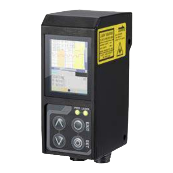
Names and Functions of Parts 1.3 Names and Functions of Parts 1.3.1 Sensor (10) (11) Number Name Function Liquid-crystal display This part displays measured results and setting screens. Screws are inserted into these holes to fix the sensor in place. Mounting holes (Diameter: 4.2 mm) Connector for... -
Page 15: Laser Emission And Measurement Ranges
Names and Functions of Parts Warning When using the sensor, never look into the laser exposure window (5). Looking directly at the laser beam may lead to loss of eyesight. Warning Put the rubber cap on the connector that is not used to protect from dust and water. Note When using the sensor, do not cover the laser exposure window (5) or the laser light reception window (6). -
Page 16: Cable Wire Colors And Roles
— Power supply GND (12) Brown — 12 to 24 V input RS-485 cable This cable is used for RS-485 communication between the LS series and a PLC or similar device. Number Color Input or output Description Orange — Yellow —... -
Page 17: Installation
Laser exposure Laser exposure direction direction The LS series performs measurements by emitting a parallel laser beam and receiving the reflected light. During measurement, ensure that the laser beam and reflected light is not blocked by the target object. Before using the product, check that stray light, which is reflected by a wall or by highly reflective objects, does not have an effect on the measurements. - Page 18 Ramco National 800-280-6933 | nsales@ramcoi.com www.Optex-Ramco.com...
-
Page 19: Setup And Measurement Procedures
Setup and Measurement Procedures Ramco National 800-280-6933 | nsales@ramcoi.com www.Optex-Ramco.com... -
Page 20: Before Using The Ls Series
2.1.1 Procedure for Using the Sensor Before you use the LS series, install and setup the sensor according to the procedure shown below. Installation and light axis adjustment Install the sensor such that you can perform accurate measurements of the measurement target. -
Page 21: Setup And Measurement Process
(6) Result judgment and output ● The measured result is compared against the threshold, and then the judgment result is output. Tips With the LS series, you can save settings related to measurements in "banks." Up to eight banks can be saved. Reference For details on banks, see "5.9.1 Banks."... -
Page 22: Quick Setup
Quick Setup 2.2 Quick Setup 2.2.1 Basic Measurement Settings You can take basic measurements simply by setting the following three items. Configure the settings from the sensor or from the LS-Navigator setup software. ● Shutter time ● Area ● Output conditions Reference For the actual screens and for information on the operations, see the following pages. -
Page 23: Return To Main Menu/Measurement Screen
Quick Setup 2.2.2 Return to Main Menu/Measurement Screen When you have finished configuring settings or when you are not sure what menu you are currently on, you can follow the procedures below to return to the main menu (the measurement screen). ●... -
Page 24: Initialize Settings
Quick Setup 2.2.3 Initialize Settings This section describes how to initialize settings. You can initialize one bank at a time or all banks at the same time. ● Related page Screen image Operation Sensor screen To initialize settings, on the "Other" tab, display the "Initialize"... -
Page 25: Operating The Sensor
Operating the Sensor Ramco National 800-280-6933 | nsales@ramcoi.com www.Optex-Ramco.com... -
Page 26: Sensor Screen
Sensor Screen 3.1 Sensor Screen 3.1.1 Details of the Screen This section explains the details of the screen display. (10) (11) Number Display item Description Operation The camera screen, profile waveform, Main screen — and set area are displayed here. Move the cursor to the tab, and then press the "SET"... -
Page 27: Screen Types And Switching Between Screens
This section explains the types of screens and how to switch between the screens. The following screens are available on the LS series. You can switch between screens by selecting the screen on the main screen or by pressing the "SET"... - Page 28 Sensor Screen 3.1.3 Key Lock Function Key Lock is available to prevent miss-operation by Key Lock Function which can be activated or released by pressing buttons. ・ Activate Key Lock Hold down the "EXIT" button and the "Down Cursor" button at a time for 3 seconds. While keys are locked, the cursor shows as "L".
-
Page 29: Main Screen
.Main Screen 3.2 .Main Screen This section explains the items that can be selected on the main screen and the operations of these items. Table items marked with "Y" in the "Bank" column can be set for each bank. In the same manner, items that have an "N"... -
Page 30: Input/Trigger
.Main Screen 3.2.2 Input/Trigger Set the operation of the input terminals and of the camera start trigger. Setting item Bank Setting value/default value General description Set the behavior of external input terminal IN1. BANK1 IN1 is used as the first bit for switching banks. Reset IN1 is used as the reset input terminal. -
Page 31: Storage
.Main Screen 3.2.3 Storage Configure the settings related to the storage function. Serial communication or LS-Navigator is required to check stored data. Bank Setting value/default value Setting item General description Storage Select data for storage. Storage not performed. Measure Stores measurement values. Profile Stores profile and measurement values. -
Page 32: Other
.Main Screen 3.2.4 Other Setting item Bank Setting value/default value General description Bank switch Select how to change between banks. In/Para Sensor operations or the input terminals will be used to change between banks. Comm Communication (including LS-Navigator) will be used to change between banks. - Page 33 .Main Screen Setting item Bank Setting value/default value General description 3, 4 The bank is changed to number 3 or 4. 5, 6 The bank is changed to number 5 or 6. 7, 8 The bank is changed to number 7 or 8. Input terminal settings IN1: Reset IN2: Hold...
-
Page 34: Setting
Setting 3.3 Setting This section explains the setting items on the setting screen. The setting screen has three sets of settings: "Camera," "Profile," and "Area." While the setting screen is displayed, judgment output (control output) is stopped and out-of-range analog current output is generated (approximately 24 mA). Table items marked with "Y"... - Page 35 Setting Camera items You can use the camera settings to configure the following items. Setting item Bank Setting value/default value General description Camera Select the camera mode. mode Hi-res All of the pixels will be used by the camera. Image acquisition time: 5 ms (with the maximum image area) Hi-spd Image capture time is reduced to 1/4 of the time in Hi-res mode.
-
Page 36: Profile
Setting 3.3.2 Profile Use the profile settings to configure the conditions for extracting profiles from the camera images. Also, when using the profile position, height, and tilt correction, set correction conditions. Profile screen Position correction reference height (blue line) Height correction Tilt correction reference position reference position... - Page 37 Setting Profile items You can use the profile settings to configure the following items. Setting item Bank Setting value/default value General description Scaling Expand or shrink the display range. Display at 100% size. The whole range will be displayed. Display at 200% size. Display at 400% size.
- Page 38 Setting Setting item Bank Setting value/default value General description H correct The position of the area at the specified height will be corrected by the difference between the master image and the measured profile. To use this function, you have to perform master image registration. Also, when you change this setting, you have to update the master image.
-
Page 39: Area
Setting 3.3.3 Area Use the area settings to set the measurement area for the profile and to set the measurement function for the measurement area. You can set up to four areas, and the measurement areas and measurement functions can be set separately for each area. - Page 40 Setting Area items You can use the area settings to configure the following items. Setting item Bank Setting value/default value General description Scaling Expand or shrink the display range. Display at 100% size. The whole range will be displayed. Display at 200% size. Display at 400% size.
-
Page 41: Graph/Calc
Graph/Calc 3.4 Graph/Calc The measured results of each area are displayed as a graph. You can also set calculation functions for adding or subtracting area measured results. (calculation target 1) (operator) You can set up to two calculation formulas in the format (calculation target 2) Example: If calculation target 1 is "area 1,"... -
Page 42: Graph Items (Area 1 To Area 4)
Graph/Calc 3.4.1 Graph Items (Area 1 to area 4) You can use the graph display settings to configure the following items. Setting item Bank Setting value/default value General description Graph scale Expand or shrink the display time axis (the horizontal axis). 1 to 6 [1] Graph range Expand or shrink the measured value display range (the vertical axis). -
Page 43: Output
Output 3.5 Output Use the output display to view the current output status and to set the judgment and analog outputs. Table items marked with "Y" in the "Bank" column can be set for each bank. In the same manner, items that have an "N"... -
Page 44: Output Items (Out1 To Out3)
Output 3.5.1 Output Items (OUT1 to OUT3) When the OUT1, OUT2, or OUT3 tab is selected, you can use the output display settings to configure the following items. Setting item Bank Setting value/default value General description Out target Select the area or calculation to set as the output target. Area1 The measured result of area 1 will be output. -
Page 45: Output Items (Outa)
Output 3.5.2 Output Items (OUTA) When the OUTA tab is selected, you can use the output display settings to configure the following items. Setting item Bank Setting value/default value General description Out target Select the area or calculation to set as the output target. Area1 The measured result of area 1 will be output. - Page 46 3-22 Ramco National 800-280-6933 | nsales@ramcoi.com www.Optex-Ramco.com...
-
Page 47: Ls-Navigator Setup Software
LS-Navigator Setup Software Ramco National 800-280-6933 | nsales@ramcoi.com www.Optex-Ramco.com... -
Page 48: Setup Software Requirements
Setup Software Requirements 4.1 Setup Software Requirements 4.1.1 Operating Environment The operating environment for this software is shown below. Item Details Computer A computer running Windows ® Base OS Microsoft Windows 2000 ® ® Microsoft Windows XP ® ® Microsoft Windows 7 ®... -
Page 49: Software Setup
Software Setup 4.2 Software Setup 4.2.1 Installing the Driver This section explains the device driver installation procedure. Tips • Before performing the installation, exit all other applications that are running on Windows ® • Log in as a user with Administrator rights before installation. Microsoft Windows 2000 ®... - Page 50 Software Setup Start installation of the driver. Click [Have disk (H)] to display a dialog box for selecting a file. Select the "ftdibus.inf" file in the folder you unzipped in step 2 of this procedure. Complete driver installation. If a confirmation screen appears, click [Next] to start installation.
-
Page 51: Install The Software
Software Setup Open the "Device Driver Installation Wizard." Click [Extract]. Proceed with the driver installation. Click [Next]. Complete the driver installation. Click [Finish]. This completes the driver installation. 4.2.2 Install the Software This section explains the setup software installation procedure. Insert the setup software user's manual CD-ROM. - Page 52 Software Setup Copy the setup software. Copy the "LS_navigator.exe" file to the folder you created. Start the setup software. Double-click the copied "LS_navigator.exe” file. Setup software LS-Navigator starts. Exit the setup software. After setup software LS-Navigator has started normally, on the “File” menu, click “eXit” or click the close button in the upper-right corner of the screen to exit the program.
-
Page 53: Settings For High-Speed Communication
Software Setup 4.2.3 Settings for High-speed Communication To enable high-speed communication with the LS, we recommend that you configure the settings as shown below. However, configuring the settings as shown here will increase load on the computer during communication. If operation becomes unstable, return the settings to their previous values. - Page 54 Software Setup Open "Device Manager." Click the [Hardware] tab, and then click [Device Manager]. Open the “Communications Port (COM XX) Properties” dialog. Click [Ports (COM & LPT)], and then click [USB Serial Port (COM XX)]. Tips The port number inserted for "XX" varies depending on your environment.
- Page 55 Software Setup Windows ® Open the "Control Panel." Click the [Start] button, and then click [Control Panel]. Open the "System and Security" category. Click [System and Security]. Open the "Device Manager." Click [Device Manager]. Open the "Communications Port (COM XX) Properties" dialog. Click [Ports (COM &...
-
Page 56: Uninstallation Procedure
Software Setup Open the "Advanced Settings for COM XX" dialog. Click the [Port Settings] tab, and then click [Advanced]. Change the "Latency Timer" setting. Select "1" from the "Latency Timer" list, and then click [OK]. Note If changing this setting causes a malfunction such as the software stopping, change the "Latency Timer"... -
Page 57: Ls-Navigator Screen And Operating Method
LS-Navigator Screen and Operating Method 4.3 LS-Navigator Screen and Operating Method 4.3.1 Start LS-Navigator Double-click the icon to start the program. 4.3.2 Main Screen (Measurement Screen) This section explains the details of the main screen (measurement screen). (17) (16) (10) (15) (14) (13) - Page 58 LS-Navigator Screen and Operating Method Number Display item Description Operation Each click of the button switches the hold operation Turn the hold operation Hold between on and off. On/off status is indicated by the lit on or off. status of the icon. Select the bank number from "1"...
-
Page 59: Common Setup
LS-Navigator Screen and Operating Method 4.3.3 Common Setup This section explains the details of the common setup screen. (10) Number Display item Description Operation Select from the list the port to use for communication. The Set the port for Port ports that are currently connected to the computer are communication. -
Page 60: How To Change Settings
LS-Navigator Screen and Operating Method 4.3.4 How to Change Settings Writing settings Setting changes are immediately applied to operation, but the changed details are cleared when the power is turned off. You can confirm the changed settings by clicking “Send Param” in the upper left of the screen. Alternatively, you can confirm the settings when configuring measurement settings by clicking “Send PARAM”... -
Page 61: Setup Procedure
Setup Procedure 4.4 Setup Procedure 4.4.1 Connecting to the Sensor Head When the sensor head and computer are connected, click "Connect" to connect to the sensor head and automatically update the measured value. If the connection fails, the message "Failed to connect to LS sensor unit." will be displayed. When you close the message, the common setup screen will be displayed. -
Page 62: Input/Trigger Settings
Setup Procedure 4.4.2 Input/Trigger Settings This section explains the details of the input/trigger setup screen. Reference For details on the input/trigger settings, see "5.2 Input/Trigger Settings." Number Display item Description Operation Configure various For each item, select a value from the list or type the Input/trigger settings related to input value. -
Page 63: Camera Settings
Setup Procedure 4.4.3 Camera Settings This section explains the details of the camera setup screen. Reference For details on the camera settings, see "5.4 Camera Settings." Number Display item Description Operation When you click this button, the latest camera image is acquired. Updates the display area (If the communication speed is slow, it may take time to acquire Refresh... - Page 64 Setup Procedure Number Display item Description Operation When "Refresh" is performed, a green bar shows the Image Shows the progress of progress of image acquisition. Image acquisition is acquisition image acquisition when complete and the image is updated when the bar reaches progress "Refresh"...
-
Page 65: Profile Settings
Setup Procedure 4.4.4 Profile Settings This section explains the details of the profile setup screen. Reference For details on the profile settings, see "5.5 Profile Settings." Setting the waveform extraction Setting the origin and tilt correction Number Display item Description Operation Refresh Updates the profile. - Page 66 Setup Procedure Number Display item Description Operation Parameter Displays settings. Displays the settings based on the selected item. display area Expand the display area in the vertical direction. Shrink the display area in the vertical direction. Expand or shrink the Scaling display area.
-
Page 67: Area Settings
Setup Procedure 4.4.5 Area Settings This section explains the details of the area setup screen. Reference For details on the area settings, see "5.6 Area Settings." Number Display item Description Operation Click this button to When you click this button, continuous updating of the Refresh perform continuous profile will start. -
Page 68: Calculation Settings
Setup Procedure 4.4.6 Calculation Settings This section explains the details of the calculation setup screen. Reference For details on the calculation settings, see "5.7 Calculation Settings." Number Display item Description Operation Selects the waveform The measured values of the areas whose check boxes you series display targets. -
Page 69: Output Settings
Setup Procedure 4.4.7 Output Settings This section explains the details of the output setup screen. Reference For details on the output settings, see "5.8 Output Settings." Number Display item Description Operation Displays the measured Displays the measured results of the target outputs. Output results of outputs 1, 2, Click an output to display its detailed settings (4). -
Page 70: Storage Function
Storage Function 4.5 Storage Function This section explains the screen that you use to access the storage function. Reference For details on the storage function and storage settings, see "5.3 Storage Settings." 4.5.1 Storage Settings This section explains the details of the storage setup screen. Storage settings are shared between "data storage"... -
Page 71: Data Storage
Storage Function 4.5.2 Data Storage This section explains the details of the data storage screen. Number Display item Description Operation Click "Start" to start the storage operation from the Start/stop the storage beginning. (The saved storage data will be discarded.) Start/Stop operation. -
Page 72: Profile Storage
Storage Function 4.5.3 Profile Storage This section explains the details of the profile storage screen. When you switch to the profile storage screen, the data in data storage is discarded. Number Display item Description Operation Click "Start" to start the storage operation from the Start/stop the storage beginning. - Page 73 Storage Function Number Display item Description Operation Displays the progress when a profile is being acquired. Displays the progress of Progress bar When the green bar reaches the right side, the acquisition data acquisition. is finished, and the display is updated. 4-27 Ramco National 800-280-6933 | nsales@ramcoi.com...
- Page 74 4-28 Ramco National 800-280-6933 | nsales@ramcoi.com www.Optex-Ramco.com...
-
Page 75: Functions
Functions Ramco National 800-280-6933 | nsales@ramcoi.com www.Optex-Ramco.com... -
Page 76: Settings Lists And Factory Settings
Settings Lists and Factory Settings 5.1 Settings Lists and Factory Settings This section contains lists of settings and the corresponding factory settings. The tables are categorized according to the sensor tabs. Table items marked with "Y" in the "Bank" column can be set for each bank. Items that have an "N" for their bank are shared between all banks. - Page 77 Settings Lists and Factory Settings Camera Item Bank Options or setting range Default value Reference page Camera mode Hi-res, Hi-spd, HDR, NR Hi-res [5.4 Camera Camera area (Set the area.) (Entire area) Settings] Auto adjust Gain 1.00 to 8.00 1.00 Shutter 5 to 10235 [μs] * In steps of 5 μs...
- Page 78 Settings Lists and Factory Settings Graph You can configure settings related to the display method of the graph of each area. Items depend on the area or calculation. The table below shows items and default values for area 1. Item Bank Options or setting range...
-
Page 79: Input/Trigger Settings
Input/Trigger Settings 5.2 Input/Trigger Settings 5.2.1 IN1/IN2/IN3/IN4 Set the operation of the external input terminals. The available selections vary depending on the terminal. IN1, IN2, and IN3 are used as bits 1 to 3 of a binary number that is used to switch the bank. Use the sensor menu to switch the functions of terminals that are not used in bank switching. -
Page 80: Input Polar, Inp Filter
Set the external input filter time to prevent chattering. Set this value in steps of 5 μs. 5.2.4 Trig action The LS series performs a measurement each time that the trigger conditions are met. Set the action of this trigger. Cont Imaging and measurements are performed continuously while the trigger is on. -
Page 81: Storage Settings
Storage Settings 5.3 Storage Settings The storage function stores measurement results and profile data to the LS. Stored data can be output via LS-Navigator or RS-485 communication. The "Graph/Calc setting" screen of the LS can be used to display stored measured values as a graph. 5.3.1 Storage Used to select storage contents. -
Page 82: Intermittent
Storage Settings Start target When "Start cond" is "Measure", "Alarm", "UP limit", or "LOW limit", this setting selects which area should be the reference of the start condition. Select from Area1 to 4, or Calc1 or 2. Threshold When "Start cond" is "UP limit" or "LOW limit", this setting specifies the threshold to be used as the start condition reference. -
Page 83: Camera Settings
Camera Settings 5.4 Camera Settings 5.4.1 Camera Mode Select the camera mode. For "Hi-res" mode and "Hi-spd" mode, one measurement is performed for each image. For "HDR" mode and "NR" mode, two images are taken by the camera for each trigger, and then one measurement is performed for these two images. - Page 84 Camera Settings Operation of the "HDR" camera mode Workpieces where HDR is effective Use this mode when measuring workpieces that have parts whose reflective status vary greatly. The following example uses a workpiece that has a white and a black part, as shown in the figure to the right. To measure this workpiece, it is necessary to acquire a profile like that shown below.
- Page 85 Camera Settings Operation in "HDR" camera mode In "HDR" mode, the brightness from images captured at fast shutter speeds is amplified. The amplification rate is determined by the ratio of the shutter speeds of the two images. (Example: If the shutter speeds are 1000 μs and 4000 μs, the amplification rate will be 4000/1000 = ×4.) During amplification, areas where the light level is low will be eliminated in advance as noise.
- Page 86 Camera Settings Camera mode: "NR" In "NR" (Noise Reduction) camera mode, two images are taken: one when the laser is on and one when the laser is off. Measurement is performed on the difference of these two images. Because the image taken when the laser is off can be canceled, this function is effective in situations where light other than that from the laser—such as noise—has an effect on the measurement.
-
Page 87: Image Brightness (Shutter Time And Gain)
Camera Settings 5.4.2 Image Brightness (Shutter Time and Gain) Use shutter time and gain to adjust the camera screen brightness. With “Auto adjust”, the shutter speed will be adjusted to the optimum value. Shutter Set the camera shutter time. Set this value in steps of 5 μs. The longer the shutter time, the brighter the images that can be taken. -
Page 88: Camera Range
Camera Settings 5.4.3 Camera Range Set the camera Range. The narrower you set the camera range, the shorter the imaging time and the sampling period become. The default value is the entire camera range. (Sampling period: 5 ms) Purpose of narrowing the camera range Narrowing the camera range has advantages such as those shown below. -
Page 89: Received Light Waveform And Measurements
Camera Settings 5.4.4 Received Light Waveform and Measurements The heights of all the parts where the laser strikes the target are measured from the waveform. The waveform is a vertical graph of the reflected light of the laser. The following two settings are related to the recognition of the received light waveform. Normally you do not have to change these settings. -
Page 90: Profile Settings
Profile Settings 5.5 Profile Settings 5.5.1 Profile Extraction Settings Target Select the measurement target from "Normal," "Gap," and "Semi-trans." "Normal” is standard. Use this setting to specify what parts of the received light waveform to use as measurement data. a) Normal The peak position of the received light waveform will be Reject level measured. - Page 91 Profile Settings c) Semi-trans Use this setting when measuring semi-transparent objects such as resin or erasers where the light enters the workpiece and causes Measured internal reflections. value With semi-transparent workpieces, the waveform profile is not stable, so the "Reject level" setting is ignored, and the center is calculated from the entire waveform.
-
Page 92: Save Master
Profile Settings 5.5.2 Save Master Register the acquired profile as the master image. The correction functions are set with the registered master image as the reference. You can save one master image for each bank. Tips When you change the reference coordinates for the height, position, or tilt correction and when you change the correction procedure, you have to register the master image again. -
Page 93: Profile Correction
When the target's position is shifted during measurement, you can correct the position and height of the area. With the LS series, you can correct the height, position, and tilt. Do not use the correction functions when absolute positions are necessary such as for web guide control. - Page 94 Profile Settings H correct Sets the threshold. If the profile exceeds the threshold, the waveform will be moved horizontally to the reference position. Set the reference height. Set the reference height, corresponding to the master image, where correction will be performed. Area The position farthest to the right or left that crosses this height will be the correction reference position.
- Page 95 Profile Settings V correct Sets the reference position. The height is adjusted so that it is equal to the height of this position. Set the reference position. Set the reference position, corresponding to the master image, at which correction will be performed. The height will be corrected so that it becomes the same as that of the measured value at this position.
- Page 96 Profile Settings Correct method Sets whether to use position and height corrections and the order to use these corrections in. ● -: Correction will not be performed. ● →: Position correction (left side) will be performed. ● ←: Position correction (right side) will be performed. ●...
- Page 97 Profile Settings Tilt correct Corrects the installation tilt and the tilt of the measurement target object. The profile tilt will be corrected so that the height correction reference position and the tilt correction reference position become level with each other. If an alarm occurs in either of the reference positions, the tilt correction will not be performed.
-
Page 98: Area Settings
Area Settings 5.6 Area Settings The LS series sets "areas" within the measurement range, and then performs measurements on these areas. You can specify up to four areas. 5.6.1 Measurement Areas Sets the positions and sizes of the areas within the camera area. -
Page 99: Meas Func
Area Settings 5.6.2 Meas func Specifys the measurement functions for the areas. You must configure different settings depending on the measurement function. Average The average of the measured values within the area Area are output. Profile Tips • Parts where an alarm occurs will not be used in the calculation of the average value. •... - Page 100 Area Settings Width The largest distance from the rightmost point to the leftmost point that cross the center of the area's height is output. Use this function when you want to find the widths of protrusions and gaps. Tips The points that are detected by the width function are the positions that are detected by "Edge pos." P pos The position of the highest measured value within the area is output.
- Page 101 Area Settings Edge pos The rightmost point or the leftmost point that crosses the center of the area's height is output. ● Detection direction Specify the direction from which to detect edges. The figure to the right shows the detection result when detection from the left is specified.
- Page 102 Area Settings Size The mathematical area of the section bounded by the profile and the specified height within the area is determined. The unit of the output value is mathematical area (mm ● Direction Select the direction in which to perform the mathematical area measurement from "↑" (from the lower side of the area up) and "↓"...
- Page 103 Area Settings Diameter An approximate circle is determined from the measured values within the area, and then the diameter of this circle is output. The unit of the output value is length (mm). ● Direction Select the direction in which to perform the measurement from "↑" (from the lower side of the area up) and "↓"...
-
Page 104: Calculation Settings
Calculation Settings 5.7 Calculation Settings Sets the processing to perform in relation to the measured values of each area. 5.7.1 Average Averaging is performed the number of times specified over the measured results of the areas. The more times specified for processing, the more stable the result, but the response speed is slower. [Setting target:] Areas 1 to 4 Tips If you have used "Smoothing"... -
Page 105: Calculation Formulas
Calculation Settings 5.7.4 Calculation Formulas You can perform calculations with the measured results of multiple areas. Set up to two calculation formulas. The calculation formulas are defined as shown below. Select from the following values for the calculation targets and for the operator. Calc target 1 Operator Calc target 2... -
Page 106: Output Settings
Output Settings 5.8 Output Settings 5.8.1 Out target Select the output target area. [Setting target:] Outputs 1 to 3 and analog output Select the target from the following parameters. ● Area1 ● Area2 The measured result of the area is set as the output target. ●... - Page 107 Output Settings Out polar The following operations are performed when On Timing is set to "Out range." For details on the operations, see the following table. ● N.O.: Output is in the "open" state when a measurement result is within the range defined by the threshold upper limit and lower limit.
-
Page 108: Out Action
Output Settings 5.8.3 Out action Set the output operation. [Setting target:] Outputs 1 to 3 Normal The output turns on when the measured value is outside of the threshold range. Upper limit Output 1shot The output turns on for the specified output time when the measured value is outside the threshold range. - Page 109 Output Settings 1shot2 The output turns on only for the specified output time when the measured value is outside the threshold Upper limit range. Since output is performed only when the measured value is outside the threshold range, output does not Output turn on when there are continuous out of range values.
-
Page 110: Offset/Offset Value
Output Settings 5.8.4 Offset/Offset Value When offset input is received, values are added to or subtracted from the current display value so that it becomes the value set with "Offset value." The offset value can be set for each output. When the offset operation is executed, values are added to or subtracted from the measured value of (1) the area that the output is referencing or (2) a calculation. -
Page 111: Analog Output Range
Sets the output range of the analog current output. To set this range, set arbitrary upper and lower limits on the output. The default output range is shown in the following figure. The analog output resolution of the LS series is approximately 0.4 μA. 24mA 20mA... -
Page 112: Common Settings
Common Settings 5.9 Common Settings 5.9.1 Banks The LS series stores measurement conditions in "banks." You can switch between banks according to the details to measure. You can use the sensor or communication to switch between banks. Bank switch ● In/Para You can use the sensor screen and input terminals to switch between banks. -
Page 113: Axis Dir
Common Settings 5.9.3 Axis dir Set the direction in which to increase and decrease the height direction measured value. Select "Near+" (the measured value will increase toward the side near to the sensor head) or "Far+" (the measured value will increase toward the side far from the sensor head). In both situations, the origin is the center of the measurement range (at 100 mm). -
Page 114: Brightness
Common Settings ● LCD OFF The back light will be completely OFF without any access to the console buttons. While LCD back light is OFF, The LS response speed of communication will be faster. 5.9.7 Brightness Adjust the brightness of the LS sensor display. The larger the number, the brighter the screen will be displayed. -
Page 115: Serial Communication
Serial Communication Ramco National 800-280-6933 | nsales@ramcoi.com www.Optex-Ramco.com... -
Page 116: Communication Specifications
Communication Specifications 6.1 Communication Specifications 6.1.1 Communication Specifications Communication method EIA RS-485 (half duplex) Transmission code Binary Data length 8 bits Stop length 1 bit Parity check None Baud rate 9600, 19.2 k, 38.4 k, 57.6 k, 115 k, 230 k, 460 k, 921 k, 2.0 M, 4.0 M (bps) Header Data delimiter Use a dedicated communication cable to perform communication. -
Page 117: Command Format
Communication Specifications 6.1.3 Command Format All sent and received commands are communicated in the following format. Label Data length Command Data part Checksum Number of bytes 0 to 510 Number of bytes Data Details STX (02h) Data length The length of the data is written in units of words. (1 word = 2 bytes) Command Communication command... -
Page 118: How To Acquire Measured Values
How to Acquire Measured Values 6.2 How to Acquire Measured Values This section explains how to use communication to acquire measured values. 6.2.1 Commands for Acquiring Measured Values Set or Send or Command Function Length Data string Parameter acquire reply (hex) a: Output Send... -
Page 119: How To Acquire Profiles
How to Acquire Profiles 6.3 How to Acquire Profiles This section explains how to use communication to acquire profile data. 6.3.1 Commands for Acquiring Profile Data Use these commands to acquire profile data. Set or Send or Command Function Length Data string Parameter acquire reply (hex) Send Acquire the Acquire 400B... - Page 120 How to Acquire Profiles The value obtained here is 0x6800. Dividing this value by 32 gives 832, which is the number of profiles. For time information, a value is input that represents a count in 0.1 ms units the time from power on and startup. Reading profiles After you acquire the address and size of the profile, read the profile values.
-
Page 121: Storage Data Acquisition Method
Storage Data Acquisition Method 6.4 Storage Data Acquisition Method This section explains how to acquire data stored using the storage function. 6.4.1 Commands for Acquiring Storage Data Use these commands to acquire storage data. Set or Send Command Function Length Data string Parameter acquire... - Page 122 Storage Data Acquisition Method 0x03E8 (hexadecimal) = 1000 (decimal), so it indicates that there are 1000 storage items of measured values and profiles (cumulative). Acquiring measured value storage data The measured value storage results are aligned starting from the address that was acquired previously. (32 bytes per data item) 253 words (506 bytes) of data can be acquired at one time, so data acquisition needs to be divided between multiple executions when the number of measured value storages is 16 or greater.
-
Page 123: Setting Acquisition And Change Commands
Command Tips The settings willl be changed when the LS series receives the command. However, the changed settings will be erased when the power is turned off. To keep the settings, send the command to write them to EEPROM. Ramco National 800-280-6933 | nsales@ramcoi.com... - Page 124 Setting Acquisition and Change Commands Reply when an error occurs Command Data Function Length Cause of error (hex) string No corresponding e001 — The corresponding command could not be found. command Invalid parameter e002 — A parameter specified by the command was invalid. Invalid packet or STX, ETX, or the packet length was invalid or a e003...
-
Page 125: Writing Settings To Eeprom
Setting Acquisition and Change Commands 6.5.2 Writing Settings to EEPROM Set or Send or Command Function Length Data string Parameter acquire reply (hex) Send 000a a: Bank number Send Param 0005 0-7, 15 (common settings) Reply 000a 6.5.3 Camera Settings Set or Send or Command... -
Page 126: Profile Settings
Setting Acquisition and Change Commands 6.5.4 Profile Settings Set or Send or Command Function Length Data string Parameter acquire reply (hex) Send 000a a: Measurement target 4002 Reply 0 Setting value Setting value Target Normal Semi-trans Send Acquire 4003 Reply 1 000a Send 000a... -
Page 127: Area Settings
Setting Acquisition and Change Commands 6.5.5 Area Settings Set or Send or Command Function Length Data string Parameter acquire reply (hex) a: Area 000abbbbccccdddd Send Setting value Setting value eeee Area1 Area3 6002 Area2 Area4 Reply 0 bbbbccccddddeeee: Area coordinates (×2) Details Input value Send... -
Page 128: Calculation Settings
Setting Acquisition and Change Commands Set or Send or Command Function Length Data string Parameter acquire reply (hex) 000abbbb Send a: Area 6004 Setting value Setting value Reply 0 Area1 Area3 Inflect Threshold Area2 Area4 000a Send bbbb: Inflect Threshold Acquire 6005 -255 ~ +255... -
Page 129: Output Settings
Setting Acquisition and Change Commands Set or Send or Command Function Length Data string Parameter acquire reply (hex) a: Calculation Send 000a000b Setting value Setting value 8002 Calc1 Calc2 Reply 0 Calc target1 b: Area Send 000a Setting value Setting value Acquire 8003 Area1... - Page 130 Setting Acquisition and Change Commands Set or Send or Command Function Length Data string Parameter acquire reply (hex) a: Output Send 000a000b Setting value Setting value a000 OUT1 OUT3 OUT2 Reply 0 Out action b: Output action Setting value Setting value Send 000a 0 Normal...
-
Page 131: Input Settings
Setting Acquisition and Change Commands 6.5.8 Input Settings Set or Send or Command Function Length Data string Parameter acquire reply (hex) a: Input Setting value Setting value Send 000a000b c000 b: Input terminal operation Reply 0 Setting value Setting value BANK1 Reset IN1 to IN4... -
Page 132: Storage Settings
Setting Acquisition and Change Commands Set or Send or Command Function Length Data string Parameter acquire reply (hex) Send aaaa 2014 Reply 0 aaa: Trigger delay time Trig delay Send 1 to 4095 [×5 ms] Acquire 2015 Reply 1 aaaa Send 000a a: Offset target... -
Page 133: Other Settings
Setting Acquisition and Change Commands 6.5.10 Other Settings Set or Send or Command Function Length Data string Parameter acquire reply (hex) Send 000a a: Bank switching method 0012 Setting value Reply 0 Bank switch In/Para Send Acquire 0013 Comm Reply 1 000a Send 000a... - Page 134 6-20 Ramco National 800-280-6933 | nsales@ramcoi.com www.Optex-Ramco.com...
-
Page 135: Specifications
Specifications Ramco National 800-280-6933 | nsales@ramcoi.com www.Optex-Ramco.com... -
Page 136: Specifications
Specifications 7.1 Specifications Model LS-100CN LS-100CP Measurement range 100 ± 25 mm Width of view (at measuring distance) 17 mm (at 75 mm), 27 mm (at 125 mm) Light source Red laser, wavelength: 655 nm, max. output: 1 mW Laser class IEC/JIS Class2 CLASS II... -
Page 137: I/O Circuit Diagrams
I/O Circuit Diagrams 7.2 I/O Circuit Diagrams 7.2.1 Input Circuit Diagram GND (blue) *PNP 12 to 24 VDC (brown) *NPN 7.5 kΩ * Selection of one of the below. Offset/stop laser emission (white) 15 kΩ Bank input 1/reset (purple) Bank input 2/hold (orange) Bank input 3/trigger (gray) 7.2.2 Output Circuit Diagrams... -
Page 138: Communication Circuit
I/O Circuit Diagrams Analog output circuit Analog output (white) Analog GND (shield) 7.2.3 RS-485 Communication Circuit 3.3 V 390 Ω A(+) (orange) 220 Ω B(-) (yellow) 390 Ω GND (black) * All other cables are N.C. (No Contact). Ramco National 800-280-6933 | nsales@ramcoi.com www.Optex-Ramco.com... -
Page 139: Dimensions
Dimensions 7.3 Dimensions Tightening torque: Emitter axis center 0.7 N•m or less Receiver axis center Liquid-crystal display Power indicator (green) Laser emission indicator (green) Connector for communication cable Main cable ø6, 12 pins (AWG #26) Ramco National 800-280-6933 | nsales@ramcoi.com www.Optex-Ramco.com... -
Page 140: Timing Charts
Timing Charts 7.4 Timing Charts This section explains the timing charts of LS series measurements and output. 7.4.1 Measurement The timing charts of LS series measurements are shown below. Tolerance judgment (upper and lower thresholds and hysteresis) When "Out polar" is "N.O." and "On Timing" is "Out range"... - Page 141 Timing Charts When the hold mode is "Sample" When the hold mode is "Sample," the value present when hold input is received is maintained. Measured value Measurement not possible Hold Reset When the hold mode is "Peak" When the hold mode is "Peak," the maximum value present while hold input is received is acquired. Sampling Sampling period...
-
Page 142: I/O
Timing Charts 7.4.2 Trigger Input filter Input filter Trigger input Ready output Measured value Strobe output Output time Trigger delay Sampling <500µs time period (Internal processing time) Tips • When "Trig action" is set to "Cont," the ready output is not generated. •... - Page 143 Timing Charts Output operation This section explains the judgment output operation. The arrows in the figure below represent output time. ● When "Trig action" is "Cont" This is the output operation when "Cont" is set for "Trig action". The figure shows the case when the output time is longer than the sampling period. Judgment result Normal 1shot...
- Page 144 Timing Charts Reset and bank switching The following timing chart shows the operations performed when changing the bank from the bank used when "Trig action" is set to "Cont" to the bank used when "Trig action" is set to "1shot." The operations of the strobe and ready outputs vary depending on the "Trig action"...
- Page 145 Attention: Not to be Used for Personnel Protection. Never use these products as sensing devices for personnel protection. Doing so could lead to serious injury or death. These sensors do not include the self-checking redundant circuitry necessary to allow their use in personnel safety applications. A sensor failure or malfunction can cause either an energized or de-energized sensor output condition.
Need help?
Do you have a question about the LS Series and is the answer not in the manual?
Questions and answers