Table of Contents
Advertisement
Quick Links
COMMAND RANGING & TELEMETRY UNIT
CORTEX
CRT
Quantum
CRT QUANTUM USER'S MANUAL
DTU 100042
5.17 –
Dec. 03, 2021
Is.Rev
Date:
Total number of page(s): 345
Safran Data Systems - Site Paris
5 Avenue des Andes - CS 90101, 91978 COURTABOEUF Cedex - FRANCE . Tél: +33 (0)1 69 82 78 00 - Fax: +33 (0)1 69 07 39 50
© Safran Data Systems
Advertisement
Table of Contents

Summary of Contents for Safran CORTEX CRT Quantum
- Page 1 Date: Total number of page(s): 345 Safran Data Systems - Site Paris 5 Avenue des Andes - CS 90101, 91978 COURTABOEUF Cedex - FRANCE . Tél: +33 (0)1 69 82 78 00 - Fax: +33 (0)1 69 07 39 50...
- Page 2 3.3.16.4 Continuous Descrambling 3.3.5.5 Dual Polarization and Frequency Combining 5.15 October 2020 4D-8PSK-TCM Capabilities April 2020 Change to Safran Data Systems 4.2.7.5.7 Always Idle / 4.2.7.5.8 Enable primary acknowledgement 4.2.7.7.4 Change Time-tag Format 5.14 November 2019 Update of Reed Solomon Coding/Decoding ratio...
- Page 3 OR TRANSLATING IN WHOLE OR IN PART SAFRAN DATA SYSTEMS. WITHOUT PRIOR WRITTEN APPROVAL OF Safran Data Systems This document is the property of © Safran Data Systems Page iii It cannot be duplicated or distributed without expressed written consent.
- Page 4 Carrier, Sub-Carrier and Bit Rate ..........................32 1.6.9. Time Code & Reference Clock Interface ..................... 33 Safran Data Systems This document is the property of © Safran Data Systems Page iv It cannot be duplicated or distributed without expressed written consent.
-
Page 5: Table Of Contents
Demodulation Capability ..........................22 3.3.1.1. Low & High Bandwidth TMU ........................... 22 3.3.1.2. Demodulation without Sub-Carrier ..........................23 Safran Data Systems This document is the property of © Safran Data Systems Page v It cannot be duplicated or distributed without expressed written consent. - Page 6 3.3.6.3.3. Differential Coder..............................66 3.3.6.3.4. Convolutional Coder ............................67 3.3.6.3.5. Constellation Mapper for 4D-8PSK-TCM ......................68 Safran Data Systems This document is the property of © Safran Data Systems Page vi It cannot be duplicated or distributed without expressed written consent.
- Page 7 With Single Convolutional Encoding ....................117 3.4.1.2.3.3. With Dual Convolutional Encoding ....................117 3.4.1.2.3.4. With Differential Encoding ......................117 Safran Data Systems This document is the property of © Safran Data Systems Page vii It cannot be duplicated or distributed without expressed written consent.
- Page 8 3.6.3.1.2. Doppler Compensation (ESA, ESA-like, Hybrid Ranging and USB Standards) ..........153 3.6.3.2. Ambiguity Solving & Quality Factor ........................154 Safran Data Systems This document is the property of © Safran Data Systems Page viii It cannot be duplicated or distributed without expressed written consent.
- Page 9 Hybrid Ranging Standard .......................... 190 3.6.13.1. General ..................................190 3.6.13.2. Tone Frequencies ..............................190 3.6.13.3. Ambiguity ................................192 Safran Data Systems This document is the property of © Safran Data Systems Page ix It cannot be duplicated or distributed without expressed written consent.
- Page 10 4.2.2. SPS Start Sequence ............................ 228 4.2.3. Configuring the CORTEX from CTX Documents ..................229 Safran Data Systems This document is the property of © Safran Data Systems Page x It cannot be duplicated or distributed without expressed written consent.
- Page 11 4.2.5.1. Common Data ................................234 4.2.5.2. CORTEX CRT Quantum Specific Data ........................235 4.2.6. CORTEX CRT Quantum File System Architecture ..................235 4.2.7. SPS System Parameters Modification ......................237 4.2.7.1. General Procedure for Changing a Registry Key ..................... 237 4.2.7.2.
- Page 12 20: DA-15 F ...................... 16 IGURE EMALE CONNECTOR FRONT VIEW 21: RS-422 ............................17 IGURE INTERFACE Safran Data Systems This document is the property of © Safran Data Systems Page xii It cannot be duplicated or distributed without expressed written consent.
- Page 13 EQUENCE TANDARD WITH 80: R (PN C ) ....................188 IGURE ANGING EQUENCE ODES TANDARD Safran Data Systems This document is the property of © Safran Data Systems Page xiii It cannot be duplicated or distributed without expressed written consent.
- Page 14 XAMPLES OF DOWNLINK CONVERTER SETUP WITH 33: E ....................... 213 ABLE XAMPLES OF UPLINK CONVERTER SETUP Safran Data Systems This document is the property of © Safran Data Systems Page xiv It cannot be duplicated or distributed without expressed written consent.
- Page 15 Farad Hertz Millimeter revolutions per minute Ohms Second Sample per second (ks/s, Ms/s,...) Volt Safran Data Systems This document is the property of © Safran Data Systems Page xv It cannot be duplicated or distributed without expressed written consent.
-
Page 16: Crt Quantum
Gaussian Minimum Shift Keying Graphical User Interface High BandWidth Intermediate Frequency IF Modulator Interface Input/Output Local Area Network Safran Data Systems This document is the property of © Safran Data Systems Page xvi It cannot be duplicated or distributed without expressed written consent. - Page 17 Signal to Noise Ratio TeleCommand TCP/IP Transport Control Protocol / Internet Protocol Time Code Reader & Generator Safran Data Systems This document is the property of © Safran Data Systems Page xvii It cannot be duplicated or distributed without expressed written consent.
- Page 18 Virtual Channel Data Unit Video Display Unit VSWR Voltage Standing Wave Ratio Wide Area Network Safran Data Systems This document is the property of © Safran Data Systems Page xviii It cannot be duplicated or distributed without expressed written consent.
- Page 19 Tropical conditions: This product is not suitable for tropical conditions. Documentation must be consulted in all cases where this symbol is marked. Safran Data Systems This document is the property of © Safran Data Systems Page xix It cannot be duplicated or distributed without expressed written consent.
- Page 20 “CE” certification has been carried out with 3-meter interconnecting cables with remote equipment. SAFRAN DATA SYSTEMS recommends the use of high quality interconnecting cables type. The high quality recommended user interconnecting cables are “shield twisted pair” or “coaxial cable” industrial type with cable shield.
- Page 21 All equipment marked with this logo must be recycled by an approved Waste Electrical and Electronic Equipment processing facility. If desired, the equipment can be returned at the customer’s expenses to Safran Data Systems for proper recycling, after asking for a RMA by sending a request to http://www.zds-fr.com/en/locations- contacts/contactsen/contacts.html.
- Page 22 30, 2021 IMPORTANT SAFETY INSTRUCTIONS The safety precautions listed below represent warnings of certain dangers of which SAFRAN DATA SYSTEMS is aware. They must be observed during all phases of operation, service, and repair of this equipment. Failure to comply with these precautions or with specific warnings elsewhere in this manual violates safety standards of design, manufacture, and intended use of the equipment.
- Page 23 To clean the equipment, use a damp cloth without detergent. Make sure that the equipment is not connected to the mains (cable disconnected). Safran Data Systems This document is the property of © Safran Data Systems Page xxiii It cannot be duplicated or distributed without expressed written consent.
- Page 24 Liability: SAFRAN DATA SYSTEMS assumes no liability if the equipment has been opened by anyone other than a SAFRAN DATA SYTEMS employee. Any maintenance must be performed by a qualified person of SAFRAN DATA SYSTEMS (a factory return is required). Safran Data Systems This document is the property of ©...
- Page 25 Laite on liitettävä suojamaadoituskoskettimilla varustettuun pistorasiaan Norge: Apparatet må tilkoples jordet stikkontakt Sverige: Apparaten skall anslutas till jordat uttag Safran Data Systems This document is the property of © Safran Data Systems Page xxv It cannot be duplicated or distributed without expressed written consent.
- Page 26 Is.Rev. 5.17 CRT QUANTUM USER'S MANUAL Date: Dec. 03, 2021Sept. 30, 2021 1. O VERVIEW This document is the property of Safran Data Systems. © Safran Data Systems Page 1 It cannot be duplicated or distributed without expressed written consent.
- Page 27 This manual contains the information necessary to install, configure, operate and maintain the SAFRAN DATA SYSTEMS PC-based Command Ranging & Telemetry Unit (CORTEX CRT Quantum). The Cortex CRT Quantum is the latest version of the Cortex CRT and can be supplied in different versions: ...
-
Page 28: Table 1: Serial Models For The Table 2: Ethernet Portsa
MSP4 70/70 DEEP- SPACE SM01037240D IS00427 MPS4 70/230 Table 1: Serial Models for the CRT Quantum This document is the property of Safran Data Systems. © Safran Data Systems Page 3 It cannot be duplicated or distributed without expressed written consent. - Page 29 Low Data Rate (House Keeping Operations) or High Data Rate Processing. 1.3. Mission of the Cortex CRT Quantum The telemetry and control telemetry unit (CORTEX CRT Quantum) performs the following functions, in IF and in baseband in a satellite control station: ...
- Page 30 On request or automatic data transmission to the Telemetry Clients, Real-time decommutation with graphical display, VC extraction for CCSDS recommendations, This document is the property of Safran Data Systems. © Safran Data Systems Page 5 It cannot be duplicated or distributed without expressed written consent.
- Page 31 Doppler measurement and time-tagging. Simulation & Testing 1.3.4. The CORTEX CRT Quantum incorporates powerful built-in simulation capabilities for functional and performance test purposes: Simulation of a PSK or PCM telemetry signal from TM formats stored on the hard disk or received over the ETHERNET LAN from a remote Simulation Client, ...
-
Page 32: Figure 1: Cortex Crt Quantum Functional Block Diagram
(limited) IRIG - B/ NASA 36 Telemetry Quick Look Time Code Figure 1: CORTEX CRT Quantum Functional Block Diagram This document is the property of Safran Data Systems. © Safran Data Systems Page 7 It cannot be duplicated or distributed without expressed written consent. -
Page 33: Figure 2 : Hardware Architecture
One Main Signal Processing board (SAFRAN DATA SYSTEMS), One Digital I/O board, associated to the 3U Interconnection panel (SAFRAN DATA SYSTEMS), One Interconnection Panel, directly integrated on chassis for IF and Time & Frequency signals, or 3U... -
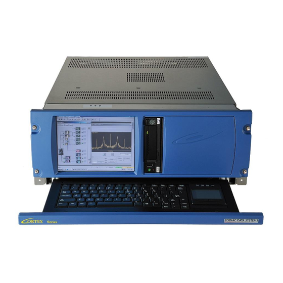
Page 34: Figure 3: Chassis Is00427 Front Panel Appearance (Front Panel Color Not Contractual)
Redundant power supply in option. Figure 3: Chassis IS00427 Front Panel Appearance (Front panel color not contractual) This document is the property of Safran Data Systems. © Safran Data Systems Page 9 It cannot be duplicated or distributed without expressed written consent. -
Page 35: Figure 4: Chassis Is00452 Front Panel Appearance (Front Panel Color Not Contractual)
5, 10 or 100 MHz clock reception and distribution to all components requiring synchronization to an accurate reference frequency. This document is the property of Safran Data Systems. © Safran Data Systems Page 10 It cannot be duplicated or distributed without expressed written consent. -
Page 36: Figure 5: Downlink Input Signal Selection
AUXILIARY input stages have limited hardware (no amplification, no filtering, no AGC). They only allow to receive noise-free signals with low amplitude variations (typically: test loops at baseband or IF, Telecommand data demodulation, etc...). This document is the property of Safran Data Systems. © Safran Data Systems Page 11... - Page 37 Video and AGC signals 1.4.2.3.2. The 3U Interconnection Panel The 3U Interconnection Panel provides full access to all signals available on the Cortex CRT Quantum. These include, in addition to the main signals described above: Video Output 1 & 2 ...
- Page 38 Test equipment. A detailed description of the Interconnection Panel is available in Section 2. Software 1.4.3. The CORTEX CRT Quantum is supplied with the following application software packages: The Signal Processing Software package (SPS), The Monitoring & Control Software package (MCS), ...
- Page 39 Windows login, Auto login enabled CORTEX CRT Quantum configuration (refer to the Cortex MCS User’s Manual), Satellite telecommanding from the Monitoring & Control software. Separate passwords for TC database modification and for TC transmission (refer to the Cortex MCS User’s Manual), ...
- Page 40 30, 2021 1.4.3.7. CORTEX Configuration at Delivery The CORTEX CRT Quantum is supplied with the hardware components and software licenses (number of telemetry chains, TM bit rate, decoding capability, commanding and ranging capability, etc…) covering the Customer requirements. The configuration of the CORTEX at delivery (hardware components & licenses) is saved to a Flash Memory chip on the MSP module.
- Page 41 223/255 223/255 239/255 239/255 ½, ⅓, ¼, Turbo decoder rate ½ ½ LDPC decoder rate This document is the property of Safran Data Systems. © Safran Data Systems Page 16 It cannot be duplicated or distributed without expressed written consent.
- Page 42 239/255 ½, ⅓, ¼, Turbo encoder rate ½ ½ (simulator only) LDPC encoder (simulator only) This document is the property of Safran Data Systems. © Safran Data Systems Page 17 It cannot be duplicated or distributed without expressed written consent.
-
Page 43: Figure 6: Crt Quantum, Crt Xl And Crt Xl2 Comparison Chart
Windows 10 IoT Windows 10 IoT Figure 6: CRT Quantum, CRT XL and CRT XL2 Comparison Chart This document is the property of Safran Data Systems. © Safran Data Systems Page 18 It cannot be duplicated or distributed without expressed written consent. - Page 44 30, 2021 1.6. Cortex CRT QUANTUM Performances On the CORTEX CRT Quantum most functions are performed digitally, mainly by powerful FPGAs. The following functions and signal processing performances are listed (this list corresponds to a fully equipped CORTEX CRT Quantum unit): ...
- Page 45 : 0.1 to 0.5 Vpp At IF : 0 to - 20 dBm 50 Ω Input impedance This document is the property of Safran Data Systems. © Safran Data Systems Page 20 It cannot be duplicated or distributed without expressed written consent.
- Page 46 Discriminator number of periods 1 to 16 Output video bandwidth Depends on the Pre-Detection filter and Discriminator programming This document is the property of Safran Data Systems. © Safran Data Systems Page 21 It cannot be duplicated or distributed without expressed written consent.
- Page 47 Integral & Dump, Raised Cosine or Root Raised Cosine Roll-off factor 0.1 to 1 This document is the property of Safran Data Systems. © Safran Data Systems Page 22 It cannot be duplicated or distributed without expressed written consent.
- Page 48 PCM coding BP-L/M/S, NRZ-L/M/S ≤ 1 dB vs theory (typical) BER degradation Eb/No measurement This document is the property of Safran Data Systems. © Safran Data Systems Page 23 It cannot be duplicated or distributed without expressed written consent.
- Page 49 ≤ 100 bits if Bit Sync. Loop BW = 1 or 3 % of BR Eb/No measurement This document is the property of Safran Data Systems. © Safran Data Systems Page 24 It cannot be duplicated or distributed without expressed written consent.
- Page 50 Yes (TM data re-modulation by the TMS in Replay mode) Off-line telemetry transmission Yes (direct transfer to the LAN of stored telemetry) This document is the property of Safran Data Systems. © Safran Data Systems Page 25 It cannot be duplicated or distributed without expressed written consent.
- Page 51 Post-detection video: 20 dB/s (*) Pre-detection PCM/video: > 30 dB/s (*) (*) under test conditions described in 3.3.5 This document is the property of Safran Data Systems. © Safran Data Systems Page 26 It cannot be duplicated or distributed without expressed written consent.
- Page 52 Carrier sweep offset 0 to 1 MHz (signed) Sweep step NCO refreshed every microsecond This document is the property of Safran Data Systems. © Safran Data Systems Page 27 It cannot be duplicated or distributed without expressed written consent.
- Page 53 Up to 8 tones defined by ratio tone frequency / long code epoch rate (code on Q rail) Integration time in multiples of long code Epoch period. This document is the property of Safran Data Systems. © Safran Data Systems Page 28...
- Page 54 �������� ���������� 2���� �� (*) Frequency & range rate computation not supported by the CORTEX. This document is the property of Safran Data Systems. © Safran Data Systems Page 29 It cannot be duplicated or distributed without expressed written consent.
- Page 55 S/W license. PCM & FMRT modes. High-level commanding interface. Pulses monitoring Local TC capability MS ACCESS database. Customized databases on request. This document is the property of Safran Data Systems. © Safran Data Systems Page 30 It cannot be duplicated or distributed without expressed written consent.
- Page 56 FSK modulation at baseband is not supported Execute instruction is not supported Data+Execute request is not supported This document is the property of Safran Data Systems. © Safran Data Systems Page 31 It cannot be duplicated or distributed without expressed written consent.
- Page 57 Doppler compensation step NCO refreshed every 160 µs, 16 µs, 1.6 µs and 0.16 µs This document is the property of Safran Data Systems. © Safran Data Systems Page 32 It cannot be duplicated or distributed without expressed written consent.
- Page 58 Time Code & Reference Clock Interface 1.6.9. The CORTEX CRT Quantum must be connected to an external timing system in the following cases: If the equipment is to be used for satellite ranging or accurate Doppler measurement. Due to the high level of performance of the unit, an external reference clock (GPS-based for example) is required to ensure phase shift and frequency measurement with the required accuracy.
- Page 59 ≤ ± 15 ppm vs temperature variations (10° to 40°) Frequency adjustment No (factory configured) This document is the property of Safran Data Systems. © Safran Data Systems Page 34 It cannot be duplicated or distributed without expressed written consent.
- Page 60 < -60 dBc in output bandwidth @Pout > -20dBm Noise density < -112 dBm/Hz This document is the property of Safran Data Systems. © Safran Data Systems Page 35 It cannot be duplicated or distributed without expressed written consent.
- Page 61 3.3 A – 1.4 A Nominal consumption 9.0 A – 4.5 A Maximum consumption Redundant power supply This document is the property of Safran Data Systems. © Safran Data Systems Page 36 It cannot be duplicated or distributed without expressed written consent.
- Page 62 Dec. 03, 2021Sept. 30, 2021 1.7. Software Licenses Consult Safran Data Systems for detailed information on the software licenses. 1.8. Reference Documentation For in-depth knowledge of the system, the reader can consult the following documents referred to in the text as RDx, where x corresponds to the document number below: ...
- Page 63 19” cabinet This document is the property of Safran Data Systems. © Safran Data Systems Page 38 It cannot be duplicated or distributed without expressed written consent.
- Page 64 Cortex CRT are being shipped, always use an ESD dissipative bag for packing the cables, such as the one used by Safran Data Systems in the original shipment. Using a regular plastic bag may result in accumulating static electricity charges in the cables, which will result in damaging or destroying the IF input amplifiers when the cables are connected to the unit.
- Page 65 5.17 CRT QUANTUM USER'S MANUAL Date: Dec. 03, 2021Sept. 30, 2021 2. H ARDWARE ESCRIPTION This document is the property of Safran Data Systems. © Safran Data Systems Page 40 It cannot be duplicated or distributed without expressed written consent.
- Page 66 The number of connectors and their mechanical characteristics depend on the model of PC-compatible workstation. Refer to Annex 4 for a detailed description of the board. This document is the property of Safran Data Systems. © Safran Data Systems Page 41...
- Page 67 Software and the external world (Monitoring & Control Software, COP Software, Control Center clients, etc…) over a single Ethernet port. The CORTEX CRT Quantum acts as a TCP-IP server for all types of data transfer. Data are exchanged using the connected-sockets communication protocol.
-
Page 68: Figure 7: Tcp-Ip Interfaces
5.17 CRT QUANTUM USER'S MANUAL Date: Dec. 03, 2021Sept. 30, 2021 Next figure illustrates the data flows between CORTEX CRT Quantum software components and between the CORTEX CRT Quantum and the external world: M&C SOFTWARE Single-client Connections Multi-client Connections CLIENTS... -
Page 69: Table 3: Udp Ports Addresses
Interconnection Panels and Associated Cables 2.3.1. Refer to Annex 5 to determine which of the following configurations is supplied with your Cortex CRT Quantum Unit. The 3U Interconnection Panel consists of a printed circuit board mounted on a metal panel and connected to the 68-pin male connector of the Digital I/O board via a Vport Samtec cable. -
Page 70: Figure 8: Integrated Simplified Interconnection Panel On Is00427
On 2U chassis, I/O ports are fitted out with 16 BNC female connectors and 6 SMA female connectors. Next figure illustrates the integrated panel appearance. Figure 9: Integrated Simplied Interconnection Panel on IS00452 This document is the property of Safran Data Systems. © Safran Data Systems Page 45... -
Page 71: Figure 10: 3U Full Interconnection Panel
Please follow the picture below for properly connecting and securing the ribbon cable to the back side of the interconnection panel: Figure 11: Ribbon cable connection and securing This document is the property of Safran Data Systems. © Safran Data Systems Page 46... - Page 72 100 Hz - 2 MHz BNC Female VIDEO IN UL V IDEO (analog signal) 2 Vpp - 50 Safran Data Systems This document is the property of © Safran Data Systems Page 1 It cannot be duplicated or distributed without expressed written consent.
- Page 73 DC to 90 MHz 0.1 to 0.5 Vpp (at BB) 0 to -20 dBm (at IF) Safran Data Systems This document is the property of © Safran Data Systems Page 2 It cannot be duplicated or distributed without expressed written consent.
- Page 74 BNC Female SYNC. PULSE Note 2 I/O NUM board External synchronization pulse input LVTTL/TTL high imp. Safran Data Systems This document is the property of © Safran Data Systems Page 3 It cannot be duplicated or distributed without expressed written consent.
- Page 75 Coherent IF level : Requires high impedance input significant from 0 dBm to –100 dBm) Safran Data Systems This document is the property of © Safran Data Systems Page 4 It cannot be duplicated or distributed without expressed written consent.
-
Page 76: Table 4: I/O Connector Panel
Note 3: These signals are on a cluster of 10 miniature coacial connectors on the rear panel of the MSP module. For Cortex CRT applications, only 5 of the 10 connectors are used. Note 4: signal level can be adjusted from registry keys. See section 4.2.8.9.4 Safran Data Systems This document is the property of © Safran Data Systems Page 5 It cannot be duplicated or distributed without expressed written consent. - Page 77 DC to 90 MHz DL AUX-2 Auxiliary input port # 2 Female 0.1 to 0.5 Vpp (at BB) Safran Data Systems This document is the property of © Safran Data Systems Page 6 It cannot be duplicated or distributed without expressed written consent.
- Page 78 Electrical characteristics Type Panel Label 0 to -20 dBm (at IF) - 50 Ω (IS00452) Safran Data Systems This document is the property of © Safran Data Systems Page 7 It cannot be duplicated or distributed without expressed written consent.
- Page 79 5, 10 or 100 MHz BNC Female 5/10 MHz IN2 Reference clock input # 2 0.2 to 5 Vpp Safran Data Systems This document is the property of © Safran Data Systems Page 8 It cannot be duplicated or distributed without expressed written consent.
-
Page 80: Table 5: I/O Connector Panel
Table 5: I/O Connector Panel Note 1: signal level can be adjusted from registry keys. See section 4.2.8.9.4 Safran Data Systems This document is the property of © Safran Data Systems Page 9 It cannot be duplicated or distributed without expressed written consent. -
Page 81: I/O Connectors Description
Uplink – IF Nominal 1 IRIG In Table 6: IS00427 I/O Connector Panel with BNC integration Safran Data Systems This document is the property of © Safran Data Systems Page 1 It cannot be duplicated or distributed without expressed written consent. -
Page 82: Configuration Sm01037242C: Comsat 4U With Efc
The computer connections (LAN, VGA, RS232) are directly available on the Industrial Computer rear panel. The picture below lists and identifies the various connections to the computer ports, and the I/O connectors of the Cortex CRT Quantum dedicated hardware. Figure 13: IS00427 Rear panel connectors with BNC integration and EFC... -
Page 83: Table 7: Is00427 I/O Connector
Table 7: IS00427 I/O Connector Panel with BNC integration and EFC Note : The signals connected at the EFC board are framed in red. Safran Data Systems This document is the property of © Safran Data Systems Page 3 It cannot be duplicated or distributed without expressed written consent. -
Page 84: Configuration Sm01037243D: Agencies / Ait 4U Without Efc
The computer connections (LAN, VGA, RS232) are directly available on the Industrial Computer rear panel. The picture below lists and identifies the various connections to the computer ports, and the I/O connectors of the Cortex CRT Quantum dedicated hardware Figure 14: IS00427 Rear panel Connectors with BNC integration and external I/O connectors... -
Page 85: Table 8: Is00427 I/O Connector
IRIG In, 1-PPS In, Video In, Auxiliary In Table 8: IS00427 I/O Connector Panel with BNC integration and External I/O connectors Safran Data Systems This document is the property of © Safran Data Systems Page 5 It cannot be duplicated or distributed without expressed written consent. -
Page 86: Integrated Panel
The computer connections (LAN, VGA, RS232) are directly available on the Industrial Computer rear panel. The picture below lists and identifies the various connections to the computer ports, and the I/O connectors of the Cortex CRT Quantum dedicated hardware Figure 15: IS00427 Rear panel Connectors with BNC integration, external I/O connectors and EFC... -
Page 87: Table 9: Is00427 I/O Connector
Table 9: IS00427 I/O Connector Panel with BNC integration, External I/O connectors and EFC Note: The signals connected at the EFC board are framed in red. Safran Data Systems This document is the property of © Safran Data Systems Page 7 It cannot be duplicated or distributed without expressed written consent. -
Page 88: Chassis 2U Is00452
2.3.1.1. The computer connections (LAN, VGA) are directly available on the Industrial Computer rear panel. The picture below lists and identifies the various connections to the computer ports, and the I/O connectors of the Cortex CRT Quantum dedicated hardware. Figure 16: Configuration S100684 Rear panel Connectors... -
Page 89: Configuration S100685: Agencies / Ait 2U Without Efc
2.3.1.1. The computer connections (LAN, VGA) are directly available on the Industrial Computer rear panel. The picture below lists and identifies the various connections to the computer ports, and the I/O connectors of the Cortex CRT Quantum dedicated hardware. Figure 17: Configuration S100685 Rear panel Connectors... -
Page 90: Configuration S100686: Comsat 2U With Efc
2.3.1.1. The computer connections (LAN, VGA) are directly available on the Industrial Computer rear panel. The picture below lists and identifies the various connections to the computer ports, and the I/O connectors of the Cortex CRT Quantum dedicated hardware. Figure 18: Configuration S100686 Rear panel Connectors... -
Page 91: Configuration S100687: Agencies / Ait With Efc
2.3.1.1. The computer connections (LAN, VGA) are directly available on the Industrial Computer rear panel. The picture below lists and identifies the various connections to the computer ports, and the I/O connectors of the Cortex CRT Quantum dedicated hardware. Figure 19: Configuration S100687 Rear panel Connectors... -
Page 92: Test Points Configuration
Refer to Annex 5 (section 1.5) for test points assignment in your machine. Safran Data Systems This document is the property of © Safran Data Systems Page 12 It cannot be duplicated or distributed without expressed written consent. -
Page 93: Video Test Points
The first measurement on the major tone (ESA, ESA-like, USB, and ESA code standard). Safran Data Systems This document is the property of © Safran Data Systems Page 13 It cannot be duplicated or distributed without expressed written consent. - Page 94 1, 2, ..., 6, 7, 0, 1 (end of code transmission), 2 (phase measurement on major tone). Safran Data Systems This document is the property of © Safran Data Systems Page 14 It cannot be duplicated or distributed without expressed written consent.
-
Page 95: Ttl And Rs422 Data I/Os
Manual and the TCP/IP Interface Specification (TMU Table) for more information on I/Q interleave, I/Q swap, I/Q invert and PCM encoding on the test points). Safran Data Systems This document is the property of © Safran Data Systems Page 15 It cannot be duplicated or distributed without expressed written consent. -
Page 96: Figure 20: Da-15 Female Connector, Front View
Q Data Output, positive RS-422 CLK_OUT_P Clock Output, positive RS-422 Table 16: Interconnection Panel. RS422 Data I/Os Safran Data Systems This document is the property of © Safran Data Systems Page 16 It cannot be duplicated or distributed without expressed written consent. -
Page 97: Figure 21: Rs-422 Interface
The resistor at the input of the user device is not necessary if the latter has already an internal impedance of 100 Ohm. Safran Data Systems This document is the property of © Safran Data Systems Page 17 It cannot be duplicated or distributed without expressed written consent. -
Page 98: Functional Description
5.17 CRT QUANTUM USER'S MANUAL Date: Dec. 03, 2021Sept. 30, 2021 3. F UNCTIONAL ESCRIPTION Safran Data Systems This document is the property of © Safran Data Systems Page 18 It cannot be duplicated or distributed without expressed written consent. -
Page 99: Monitoring & Control
3.1.1. 3.1.1.1. Standard Monitoring Protocol The CORTEX CRT Quantum supplies its status upon request from a Monitoring Client. On reception of a monitoring request, the CORTEX CRT Quantum checks its validity. If the request is correct, it returns a monitoring message embedded in an ETHERNET packet to the Control Center. In case of invalid request, the CORTEX CRT Quantum returns a negative acknowledgment message. -
Page 100: Low Bandwidth Monitoring Protocol
Simultaneous connection of several Control Clients to the Control port is not allowed for security reasons. Safran Data Systems This document is the property of © Safran Data Systems Page 20 It cannot be duplicated or distributed without expressed written consent. -
Page 101: Logging
General 3.2.1. The CORTEX CRT Quantum reports on the Logging port all changes in its configuration, as well as satellite TC requests, TC instructions and associated acknowledgement messages exchanged over the Telecommand port. It is also possible to log 4 specific monitoring flows (SPS Kernel ≥ e3r9) Up to five Logging Clients can be simultaneously connected to the Logging port. -
Page 102: If Demodulation & Telemetry Processing
(**): NRZ codes, PM/PCM BIP < 2.5 Mbps, FM/PCM BIP < 1 Mbps Safran Data Systems This document is the property of © Safran Data Systems Page 22 It cannot be duplicated or distributed without expressed written consent. -
Page 103: Demodulation Without Sub-Carrier
20 Mbps 10 Msps 20 Mbps Table 19: Performance limitation for FULL Direct PCM Demodulation Safran Data Systems This document is the property of © Safran Data Systems Page 23 It cannot be duplicated or distributed without expressed written consent. - Page 104 10 Mbps 5 Msps 10 Mbps Table 20: Performance limitation for STANDARD Direct PCM Demodulation Safran Data Systems This document is the property of © Safran Data Systems Page 24 It cannot be duplicated or distributed without expressed written consent.
-
Page 105: Table 21: Performancel
The performances limitations for AQPSK demodulation apply to each Telemetry Unit (I & Q channels). Safran Data Systems This document is the property of © Safran Data Systems Page 25 It cannot be duplicated or distributed without expressed written consent. -
Page 106: Constellation Convention
Safran Data Systems This document is the property of © Safran Data Systems Page 26 It cannot be duplicated or distributed without expressed written consent. -
Page 107: Gmsk Demodulation
By pre-coding the GMSK signal at the transmitter to remove the inherent differential encoding, the BER can be halved. Safran Data Systems This document is the property of © Safran Data Systems Page 27 It cannot be duplicated or distributed without expressed written consent. -
Page 108: Soqpsk Demodulation
SOQPSK-MIL SOQPSK-B SOQPSK-TG SOQPSK-A -2.5 -1.5 -0.5 Frequency (Bit Rates) Safran Data Systems This document is the property of © Safran Data Systems Page 28 It cannot be duplicated or distributed without expressed written consent. -
Page 109: 8Psk Demodulation
03, 2021Sept. 30, 2021 3.3.1.2.5. 8PSK Demodulation In 8PSK, the following constellation mappings are supported. Safran Data Systems This document is the property of © Safran Data Systems Page 29 It cannot be duplicated or distributed without expressed written consent. -
Page 110: Fm Demodulation
] − �� + ���������� �������� ���� ���� ���� �� �� �� ⁄ ���� �� �� �� �� �� Safran Data Systems This document is the property of © Safran Data Systems Page 30 It cannot be duplicated or distributed without expressed written consent. -
Page 111: Table 22: Cartesian - To -Polars
150 kHz 2.5 Msps 5 to 100 kHz 312.5 ksps Table 22: Cartesian-to-Polar Sampling Frequencies Safran Data Systems This document is the property of © Safran Data Systems Page 31 It cannot be duplicated or distributed without expressed written consent. -
Page 112: Pcm/Fm Modulation
CCSDS recommends a peak deviation equal to 0.35 times the bit rate, that gives a modulation index of h=0.7. Safran Data Systems This document is the property of © Safran Data Systems Page 32 It cannot be duplicated or distributed without expressed written consent. -
Page 113: Time Code Decoding & Data Time-Tagging
Note: Multi-symbol curve is obtained in perfect conditions (no signal distortion, no variation on modulation index) with “Propagation factor” parameter set to 0.9, Safran Data Systems This document is the property of © Safran Data Systems Page 33 It cannot be duplicated or distributed without expressed written consent. -
Page 114: Reference Frequency
Selecting this mode, the demodulator analyses the received signal and estimates the modulation index. This mode is recommended when using an analog modulator. Safran Data Systems This document is the property of © Safran Data Systems Page 34 It cannot be duplicated or distributed without expressed written consent. -
Page 115: Optional Rf Stage
Modulation index of PCM/FM signal Figure 23 : Required Eb/No to obtain BER = 10 with MS-FM demodulator Safran Data Systems This document is the property of © Safran Data Systems Page 35 It cannot be duplicated or distributed without expressed written consent. -
Page 116: Synthesizer Specifications
Using this configuration in perfect conditions, the degradation, compared to the optimal value (0.9), is only 0.5 dB. However, the detector is much more robust against any channel imperfections. Safran Data Systems This document is the property of © Safran Data Systems Page 36 It cannot be duplicated or distributed without expressed written consent. -
Page 117: If Level Measurement
The operating mode can be changed in the Windows registry (for more details, see also Section 4.2.8.3). Safran Data Systems This document is the property of © Safran Data Systems Page 37 It cannot be duplicated or distributed without expressed written consent. -
Page 118: Installation
Ex: Video Signal |A| (dB) Noise + Margin Threshold Frequency Highest Center frequency signal Peak-to-peak acquisition range Safran Data Systems This document is the property of © Safran Data Systems Page 38 It cannot be duplicated or distributed without expressed written consent. -
Page 119: Shipping
Max Value - Margin Threshold Noise + Margin Threshold Frequency Center frequency Center spectrum line Peak-to-peak acquisition range Safran Data Systems This document is the property of © Safran Data Systems Page 39 It cannot be duplicated or distributed without expressed written consent. -
Page 120: Hardware Description
Max Value - Margin Threshold Noise + Margin Threshold Frequency Center frequency Spectrum barycentre Peak-to-peak acquisition range Safran Data Systems This document is the property of © Safran Data Systems Page 40 It cannot be duplicated or distributed without expressed written consent. -
Page 121: Cortex Crt Quantum Integration
Note that the loop bandwidth can be changed while the spectrum is being scanned. 3.3.2.1.8. Acquisition By-Pass The tracked frequency is the center frequency set by the user. Safran Data Systems This document is the property of © Safran Data Systems Page 41 It cannot be duplicated or distributed without expressed written consent. -
Page 122: Tcp-Ip Interfaces
The acquisition process is by-passed in these modes (by-passed IFR, Spectrum analysis and non-coherent AM). Safran Data Systems This document is the property of © Safran Data Systems Page 42 It cannot be duplicated or distributed without expressed written consent. -
Page 123: If Receiver In Pcm Mode
Note: It must be checked that the programmed acquisition range and the expected maximum Doppler values are consistent. The higher the acquisition range is, the longer will be the acquisition process. Safran Data Systems This document is the property of © Safran Data Systems Page 43 It cannot be duplicated or distributed without expressed written consent. -
Page 124: Udp Interface For Telemetry Data Flow
IGHEST YMBOL IRST 150 < 150 KSPS KSPS FFT Narrow spectrum FFT wide spectrum Safran Data Systems This document is the property of © Safran Data Systems Page 44 It cannot be duplicated or distributed without expressed written consent. -
Page 125: Integrated Simplified Interconnection Panel
��. ���� �� ��. ���� �� �� √ �� �� ⁄ �� �� ��. ���� ���� Safran Data Systems This document is the property of © Safran Data Systems Page 45 It cannot be duplicated or distributed without expressed written consent. -
Page 126: Full Interconnection Panel (3U)
3 Hz 1 Hz .001 .000 .000 C/N0 (dB.Hz) Figure 24: 2nd Order PLL Tracking capacity Safran Data Systems This document is the property of © Safran Data Systems Page 46 It cannot be duplicated or distributed without expressed written consent. -
Page 127: Rd Order Pll
3 Hz 1 Hz 1.000E-04 .100E-04 .010E-04 C/N0 (dB.Hz) Figure 25: 3rd Order PLL Tracking capacity Safran Data Systems This document is the property of © Safran Data Systems Page 47 It cannot be duplicated or distributed without expressed written consent. -
Page 128: Doppler Measurement
Samples are stored for further transmission, in a measurement block which size is programmable between 1 and 1000 elementary measurement(s). The first measurement in the block is time-tagged. Safran Data Systems This document is the property of © Safran Data Systems Page 48 It cannot be duplicated or distributed without expressed written consent. -
Page 129: Interpolation Process
In most cases, user would not use cranky values for the sampling rate. Thus, no interpolation would be applied, because accumulated phase is generated synchronously with the sampling rate dates. Safran Data Systems This document is the property of © Safran Data Systems Page 49 It cannot be duplicated or distributed without expressed written consent. -
Page 130: Doppler Computing
) Hz for a sampling period Ts of 0.1 s, and lower than (41.6 + 6.25x10 Hz for a sampling period Ts of 10s. Safran Data Systems This document is the property of © Safran Data Systems Page 50 It cannot be duplicated or distributed without expressed written consent. -
Page 131: Impact Of Phase Errors On Doppler Computing
With a typical value of 70 MHz, the Doppler computing error will be 3.8 mHz with Ts = 0.125s. Safran Data Systems This document is the property of © Safran Data Systems Page 51 It cannot be duplicated or distributed without expressed written consent. -
Page 132: Error Due To Floating Representation
3.3.5. 3.3.5.1. General The CORTEX CRT Quantum allows to combine two IF signals from two different polarizations, in post-detection or pre-detection mode. This processing is available when the IF Receivers are in Video mode (PM or FM demodulations) or PCM mode (direct PCM demodulation). -
Page 133: Post Detection Diversity Combining
Receiver. Safran Data Systems This document is the property of © Safran Data Systems Page 53 It cannot be duplicated or distributed without expressed written consent. -
Page 134: Pre Detection Diversity Combining
In PCM mode, its value is given in percentage of the symbol rate and goes from 0.001% to 0.3%. Safran Data Systems This document is the property of © Safran Data Systems Page 54 It cannot be duplicated or distributed without expressed written consent. -
Page 135: Outputs
IF Demodulation Bit Synchronization BP, DM-M/S decoding Figure 28 : Post detection Diversity Combining outputs Safran Data Systems This document is the property of © Safran Data Systems Page 55 It cannot be duplicated or distributed without expressed written consent. -
Page 136: Pre Detection Diversity Combining
Channel B Polarization 2 Predetection filtering Level measurement Figure 29: Pre detection Diversity Combining outputs Safran Data Systems This document is the property of © Safran Data Systems Page 56 It cannot be duplicated or distributed without expressed written consent. -
Page 137: Signal Processing
( ���� ) ������������������ �������� ��ℎ���������� Combining Gain Best channel level - Worst channel level in dB Safran Data Systems This document is the property of © Safran Data Systems Page 57 It cannot be duplicated or distributed without expressed written consent. -
Page 138: Signal Routing
During IF signal acquisition. Note that when both IF Receivers are unlocked, Channel A is routed to output 1 and Channel B to output 2. Safran Data Systems This document is the property of © Safran Data Systems Page 58 It cannot be duplicated or distributed without expressed written consent. -
Page 139: Dual Polarization And Frequency Combining
Polarization only combining with the Polarization combiner labelled “F1 TM”, Frequency only combining with the F1/F2 Frequency combiner. Safran Data Systems This document is the property of © Safran Data Systems Page 59 It cannot be duplicated or distributed without expressed written consent. - Page 140 Remark: When used for frequency combination, in case the 2 input channels are the outputs of the polarization combiners, the base-band transposition and the filtering blocs are by-passed. Safran Data Systems This document is the property of © Safran Data Systems Page 60 It cannot be duplicated or distributed without expressed written consent.
-
Page 141: Data Decoding
(for example bi-phase PCM coding) or convolutional codes. Descrambling by the CORTEX CRT Quantum complies to the CCSDS recommendation CCSDS 131.0-B-3 The pseudo-random sequence should be generated using the following polynomial: ℎ ( �� ) = ��... -
Page 142: Convolutional Decoding
3.3.6.2. Convolutional Decoding Convolutional coding technique is well suited for telemetry channels with predominant Gaussian noise. Convolutional decoding and error-correction by the CORTEX CRT Quantum complies to the CCSDS recommendation CCSDS 131.0-B-3. The following coding characteristics should be used: Convolutional code with maximum likelihood (Viterbi) decoding ... -
Page 143: 8Psk-Tcm Decoding
Figure 31: Probability of Bit Error versus Eb/No. Ref : CCSDS 413.0-G-2 (§ B2.3), October 2009 Safran Data Systems This document is the property of © Safran Data Systems Page 63 It cannot be duplicated or distributed without expressed written consent. -
Page 144: Introduction
The performances of 4D-8PSK-TCM scheme can be substantially improved when concatenated with Reed Solomon (R-S). Safran Data Systems This document is the property of © Safran Data Systems Page 64 It cannot be duplicated or distributed without expressed written consent. -
Page 145: 8Psk-Tcm Coder
In fact, the serial to parallel conversion is a byte (8 bits) to symbol (8 to 11 bits) conversion that will be described later. Safran Data Systems This document is the property of © Safran Data Systems Page 65 It cannot be duplicated or distributed without expressed written consent. -
Page 146: Differential Coder
8 adder is also shown; it is applicable to both the coder mapper and differential coder. Safran Data Systems This document is the property of © Safran Data Systems Page 66 It cannot be duplicated or distributed without expressed written consent. -
Page 147: Convolutional Coder
1/8, 1/9, 1/10, or 1/11 of the information rate Safran Data Systems This document is the property of © Safran Data Systems Page 67 It cannot be duplicated or distributed without expressed written consent. -
Page 148: Constellation Mapper For 4D-8Psk-Tcm
π/4 and will be differentially encoded. Equation for 2 bits/channel symbol efficiency: Safran Data Systems This document is the property of © Safran Data Systems Page 68 It cannot be duplicated or distributed without expressed written consent. -
Page 149: Reed-Solomon Decoding
Reed-Solomon coding technique is well suited for burst error correction. It can be used in conjunction with Viterbi coding to allow data reconstruction with the lowest error probability. Reed-Solomon decoding and error- correction by the CORTEX CRT Quantum complies to the CCSDS recommendation CCSDS 131.0-B-3. The following coding characteristics should be used: ... -
Page 150: Turbo Decoding
Tel: +33 2 99 12 48 05, Fax: +33 2 99 12 40 98 E-mail: christian.hamon@cnet.francetelecom.fr Turbo decoding and error-correction by the CORTEX CRT Quantum complies to CCSDS recommendation CCSDS 131.0-B-3. The Turbo decoder implements the Log-MAP algorithm and with 4 bits input quantized soft values. - Page 151 Figure 33: Probability of Bit Error versus Eb/No. Ref : Turbo-Concept - CCSDS turbo decode progress report 5 - May 23, 2008 Safran Data Systems This document is the property of © Safran Data Systems Page 71 It cannot be duplicated or distributed without expressed written consent.
-
Page 152: Probability Of Bit Error
) + 20 log (�� 0 (����������) 0 (������) (������������) − 10 log ���� (������������) Safran Data Systems This document is the property of © Safran Data Systems Page 72 It cannot be duplicated or distributed without expressed written consent. -
Page 153: Pcm/Bpsk Square/Pm (Low Or High Bandwidth)
CCSDS recommended synchronization word (default) or user set synchronization words Other characteristics: see CCSDS 131.0-B-3 Safran Data Systems This document is the property of © Safran Data Systems Page 73 It cannot be duplicated or distributed without expressed written consent. - Page 154 CRT - BPSK - 10 Mbps Figure 35: CRT LDPC BER performance compared to CCSDS (r=1/2, k=4096) Safran Data Systems This document is the property of © Safran Data Systems Page 74 It cannot be duplicated or distributed without expressed written consent.
- Page 155 4/5 1k 4/5 4k 4/5 16k 7/8 7k Figure 36: CCSDS BER performance for all rates Safran Data Systems This document is the property of © Safran Data Systems Page 75 It cannot be duplicated or distributed without expressed written consent.
-
Page 156: Ambiguities Solving, I/O Ports & By-Passing Capabilities
Telemetry Unit. Select Auxiliary port # 1 or # 2. The signal is expected to have no DC offset at the AUXILIARY input. Safran Data Systems This document is the property of © Safran Data Systems Page 76 It cannot be duplicated or distributed without expressed written consent. -
Page 157: High Bandwidth Tmu With Sub-Carrier
Synchronizer Bit synchronizer (Option) Video Differential encoder Invert/ swap I out (Option) Safran Data Systems This document is the property of © Safran Data Systems Page 77 It cannot be duplicated or distributed without expressed written consent. - Page 158 Option: Direct input to the Bit Synchronizer is also accessible using offset 29 in the telemetry unit table with value 1 or 2. Safran Data Systems This document is the property of © Safran Data Systems Page 78 It cannot be duplicated or distributed without expressed written consent.
-
Page 159: High Bandwidth Direct Pcm: No Viterbi Decoding
& B/S Differential Differential encoder encoder Invert/ swap Interleaving I out Q out (Option) Safran Data Systems This document is the property of © Safran Data Systems Page 79 It cannot be duplicated or distributed without expressed written consent. - Page 160 & B/S Differential Differential encoder encoder Invert/ swap Interleaving I out Q out (Option) Safran Data Systems This document is the property of © Safran Data Systems Page 80 It cannot be duplicated or distributed without expressed written consent.
- Page 161 Auxiliary inputs: restricted to noise & spurious-free signal with limited amplitude variations. Direct input to the Bit Synchronizer: Not available. Safran Data Systems This document is the property of © Safran Data Systems Page 81 It cannot be duplicated or distributed without expressed written consent.
-
Page 162: High Bandwidth Pcm: Single Viterbi Decoding
Synchronizer OQPSK Q rail demodulator & B/S (Option) differential encoder invert/ swap I out (Option) Safran Data Systems This document is the property of © Safran Data Systems Page 82 It cannot be duplicated or distributed without expressed written consent. - Page 163 Auxiliary inputs: restricted to noise & spurious-free signal with limited amplitude variations. Direct input to the Bit Synchronizer: Not available. Safran Data Systems This document is the property of © Safran Data Systems Page 83 It cannot be duplicated or distributed without expressed written consent.
-
Page 164: High Bandwidth Direct Pcm: Dual Dcoding
(Option) differential differential encoder encoder invert/ swap interleaving I out Q out (Option) Safran Data Systems This document is the property of © Safran Data Systems Page 84 It cannot be duplicated or distributed without expressed written consent. - Page 165 (Option) differential differential encoder encoder invert/ swap interleaving I out Q out (Option) Safran Data Systems This document is the property of © Safran Data Systems Page 85 It cannot be duplicated or distributed without expressed written consent.
- Page 166 Auxiliary inputs: restricted to noise & spurious-free signal with limited amplitude variations. Direct input to the Bit Synchronizer: Not available. Safran Data Systems This document is the property of © Safran Data Systems Page 86 It cannot be duplicated or distributed without expressed written consent.
-
Page 167: High Bandwidth Direct Pcm: Dqpsk Or Doqpsk
& B/S Differential Differential encoder encoder Invert/ swap Interleaving I out Q out (Option) Safran Data Systems This document is the property of © Safran Data Systems Page 87 It cannot be duplicated or distributed without expressed written consent. - Page 168 & B/S Differential Differential encoder encoder Invert/ swap Interleaving I out Q out (Option) Safran Data Systems This document is the property of © Safran Data Systems Page 88 It cannot be duplicated or distributed without expressed written consent.
- Page 169 Auxiliary inputs: restricted to noise & spurious-free signal with limited amplitude variations. Direct input to the Bit Synchronizer: Not available. Safran Data Systems This document is the property of © Safran Data Systems Page 89 It cannot be duplicated or distributed without expressed written consent.
-
Page 170: High Bandwidth Pcm: Dual + Differential Decoding
& B/S decoder (Option) differential differential encoder encoder invert/ swap interleaving I out Q out (Option) Safran Data Systems This document is the property of © Safran Data Systems Page 90 It cannot be duplicated or distributed without expressed written consent. - Page 171 & B/S decoder (Option) differential differential encoder encoder invert/ swap interleaving I out Q out (Option) Safran Data Systems This document is the property of © Safran Data Systems Page 91 It cannot be duplicated or distributed without expressed written consent.
- Page 172 Auxiliary inputs: restricted to noise & spurious-free signal with limited amplitude variations. Direct input to the Bit Synchronizer: Not available. Safran Data Systems This document is the property of © Safran Data Systems Page 92 It cannot be duplicated or distributed without expressed written consent.
-
Page 173: High Bandwidth Direct Pcm: Aqpsk
(Option) Differential Differential encoder encoder invert/ invert/ swap swap I out I out (Option) (Option) Safran Data Systems This document is the property of © Safran Data Systems Page 93 It cannot be duplicated or distributed without expressed written consent. - Page 174 Auxiliary inputs: restricted to noise & spurious-free signal with limited amplitude variations. Direct input to the Bit Synchronizer: Not available. Safran Data Systems This document is the property of © Safran Data Systems Page 94 It cannot be duplicated or distributed without expressed written consent.
-
Page 175: Frame Synchronization
« j » is programmable between 0 and 7 (inclusive) referred to as the LTS (Lock-To-Search) threshold. Safran Data Systems This document is the property of © Safran Data Systems Page 95 It cannot be duplicated or distributed without expressed written consent. -
Page 176: Psk Ambiguity Solving
(to within n bits), the signal inversion is confirmed and the frame synchronizer switches to the CHECK phase. Safran Data Systems This document is the property of © Safran Data Systems Page 96 It cannot be duplicated or distributed without expressed written consent. -
Page 177: Frame Synchronizer Operating Modes
In Video Post-detection mode, we have 2 available outputs on the DCU. So the link between TMU and IFR depends on Output 1 and 2 values. Safran Data Systems This document is the property of © Safran Data Systems Page 97 It cannot be duplicated or distributed without expressed written consent. -
Page 178: Frame Verification
« Last bit ». The time-tag accuracy (provided that the selected time-tag coding is Code 2 – Refer to the MCS User’s Manual and to the TCP-IP Interface Specification) is within ±50µs (without external 1- PPS) or ±100ns (with external 1-PPS) of the reference time supplied to the CORTEX CRT Quantum. Safran Data Systems This document is the property of ©... -
Page 179: Real-Time Of Off-Line Telemetry Server
Real-time and off-line telemetry data are transmitted only on reception of a telemetry request from the Telemetry Client. On reception of a telemetry request, the CORTEX CRT Quantum checks its validity and returns a negative telemetry acknowledgment message (invalid request) or Telemetry Messages (valid request) to the Telemetry Client. -
Page 180: Telemetry Data Flows
Graphical User Interface (telemetry « Quick Look »). Refer to the MCS User’s Manual. Safran Data Systems This document is the property of © Safran Data Systems Page 100 It cannot be duplicated or distributed without expressed written consent. -
Page 181: Telemetry Data Storage On The Disk
FIFO structure. Modification of the storage capacity (maximum number of files and file size) is by system parameters and requires restarting the CORTEX CRT Quantum. Telemetry frames or blocks of raw data (or dummy frames if the telemetry chain is unlocked) are stored on the... - Page 182 Bitrate configuration used when recording the frames Time code configuration used when recording the frames. Safran Data Systems This document is the property of © Safran Data Systems Page 102 It cannot be duplicated or distributed without expressed written consent.
-
Page 183: Blind Equalization
A better solution for equalizing the incoming signal is to use an automatic adaptive equalizer. Safran Data Systems This document is the property of © Safran Data Systems Page 103 It cannot be duplicated or distributed without expressed written consent. -
Page 184: Deaf
Without equalization, the measured Eb/N0 of the received signal is very low (4 dB). That can be seen on the constellation plot of the signal, where the effect of ISI is clear: Safran Data Systems This document is the property of © Safran Data Systems Page 104 It cannot be duplicated or distributed without expressed written consent. - Page 185 “Save filter”: that allows avoiding waiting the next time the same signal will be acquired. Safran Data Systems This document is the property of © Safran Data Systems Page 105 It cannot be duplicated or distributed without expressed written consent.
-
Page 186: Configuration Of The Deaf Algorithm
Custom filters are saved in a folder specific to each TMU. The path to this folder is chosen in the registry key HKEY_LOCAL_MACHINE\SOFTWARE\In-snec\CortexCRT\SetDefaultN\Preferences\TmuX\DEAFFirPath Safran Data Systems This document is the property of © Safran Data Systems Page 106 It cannot be duplicated or distributed without expressed written consent. -
Page 187: Descrambling Mode (Lfsr Polynomials)
Note that for CCSDS mode and After and/or Before mode, the descrambling will always restart the PN sequence when hitting the sync word. The sync word is still not descrambled. Safran Data Systems This document is the property of © Safran Data Systems Page 107 It cannot be duplicated or distributed without expressed written consent. -
Page 188: Continuous Descrambling
G3RUH encoding: �� = �� + �� Figure 50 Continuous Scrambling and Descrambling Safran Data Systems This document is the property of © Safran Data Systems Page 108 It cannot be duplicated or distributed without expressed written consent. -
Page 189: Utoa (Time Of Arrival Precise Measurements)
BPL/BPM/BPS + NRZL/NRZM/NRZS + CCSDS Scrambling BPL + Viterbi / Viterbi inverted + NRZL/NRZM/NRZS + CCSDS Scrambling Safran Data Systems This document is the property of © Safran Data Systems Page 109 It cannot be duplicated or distributed without expressed written consent. -
Page 190: Registry Configuration
Also Cf. status at offset 49 of the “Telemetry Unit Table” at §2.2.2.10 of document STI100013 to check wether the UTOA processing unit is locked onto the signal or not. Safran Data Systems This document is the property of © Safran Data Systems Page 110 It cannot be duplicated or distributed without expressed written consent. -
Page 191: If Modulation & Telemetry Simulation
: Performed by hardware, firmware and/or software. Connector label on the Interconnection Panel: italic characters. Safran Data Systems This document is the property of © Safran Data Systems Page 111 It cannot be duplicated or distributed without expressed written consent. -
Page 192: Low Bandwidth Scenario
(Option) (Option) RNG sequence Base-band generation Modulation index Figure 51: Low Bandwidth Uplink Scenario Safran Data Systems This document is the property of © Safran Data Systems Page 112 It cannot be duplicated or distributed without expressed written consent. -
Page 193: High Bandwidth Scenario
Modulation index Figure 52: High Bandwidth Uplink Scenario with PCM Input Signal (PM, FM) Safran Data Systems This document is the property of © Safran Data Systems Page 113 It cannot be duplicated or distributed without expressed written consent. -
Page 194: Video + Pcm Input Signals
Figure 53: High Bandwidth Uplink Scenario with PCM and Video Input Signals (PM, FM) Safran Data Systems This document is the property of © Safran Data Systems Page 114 It cannot be duplicated or distributed without expressed written consent. -
Page 195: Bpsk Modulation
Built-in TMS or TCU (Option) (Option) Data & clock monitoring Figure 54: High Bandwidth Uplink Scenario (BPSK) Safran Data Systems This document is the property of © Safran Data Systems Page 115 It cannot be duplicated or distributed without expressed written consent. -
Page 196: Qpsk And Oqpsk Modulation
I in Q in (Option) Figure 55: High Bandwidth Uplink Scenario ( QPSK, OQPSK without Convolutional Encoding) Safran Data Systems This document is the property of © Safran Data Systems Page 116 It cannot be duplicated or distributed without expressed written consent. -
Page 197: With Single Convolutional Encoding
Data & clock monitoring Figure 58: High Bandwidth Uplink Scenario (QPSK, OQPSK with Differential Encoding) Safran Data Systems This document is the property of © Safran Data Systems Page 117 It cannot be duplicated or distributed without expressed written consent. -
Page 198: With Dual Convolutional And Differential Encoding
Data & clock monitoring Figure 59: High Bandwidth Uplink Scenario (QPSK, OQPSK with Dual and Differential Encoding) Safran Data Systems This document is the property of © Safran Data Systems Page 118 It cannot be duplicated or distributed without expressed written consent. -
Page 199: Aqpsk Modulation
External data + clock Built-in TMS-2 Data & clock monitoring Figure 60: High Bandwidth Uplink Scenario (AQPSK) Safran Data Systems This document is the property of © Safran Data Systems Page 119 It cannot be duplicated or distributed without expressed written consent. -
Page 200: Noise Generator Option
Between 8 and 12 times the symbol rate (with a minimum of 800 kHz) when the latter is less than 3.125 Msps. Safran Data Systems This document is the property of © Safran Data Systems Page 120 It cannot be duplicated or distributed without expressed written consent. -
Page 201: Telemetry Simulation
Date: Dec. 03, 2021Sept. 30, 2021 Telemetry Simulation 3.4.3. 3.4.3.1. General The Telemetry Simulator (TMS) allows for exhaustive testing of all of the software functionalities and hardware resources in the CORTEX CRT Quantum: Functional tests Telemetry reception processing without noise baseband demodulation, bit synchronization, data decoding, frame synchronization). -
Page 202: Table 23: Prn Generator Polynomials
Synchronizer has to be disabled. degree polynomial degree polynomial degree polynomial Table 23: PRN generator polynomials Safran Data Systems This document is the property of © Safran Data Systems Page 122 It cannot be duplicated or distributed without expressed written consent. -
Page 203: Encoding
In this case the data shall be organized in the file according to the following structure: Safran Data Systems This document is the property of © Safran Data Systems Page 123 It cannot be duplicated or distributed without expressed written consent. -
Page 204: Turbo-Code
The length of (sync. Marker + Turbo codeblock) is given by the formula: (32 + �� + 4) �� Safran Data Systems This document is the property of © Safran Data Systems Page 124 It cannot be duplicated or distributed without expressed written consent. - Page 205 Uncoded information data block # 2 Uncoded information data block # N Figure 63: TMS File structure for Turbo encoding Safran Data Systems This document is the property of © Safran Data Systems Page 125 It cannot be duplicated or distributed without expressed written consent.
-
Page 206: Ldpc Encoding
In this case the data shall be organized in the file according to the following structure: Safran Data Systems This document is the property of © Safran Data Systems Page 126 It cannot be duplicated or distributed without expressed written consent. - Page 207 Uncoded information data block # 2 Uncoded information data block # N Figure 64: TMS File structure for LDPC encoding Safran Data Systems This document is the property of © Safran Data Systems Page 127 It cannot be duplicated or distributed without expressed written consent.
-
Page 208: Uplink Digital Filter
The curves below show the half-band response of each filter: Figure 65: "125 kHz" filter, -3 dB bandwidth: 1.36 MHz Safran Data Systems This document is the property of © Safran Data Systems Page 128 It cannot be duplicated or distributed without expressed written consent. - Page 209 Figure 66: "250 kHz" filter, -3 dB bandwidth: 2.06 MHz Figure 67: "500 kHz" filter, -3 dB bandwidth: 2.4 MHz Safran Data Systems This document is the property of © Safran Data Systems Page 129 It cannot be duplicated or distributed without expressed written consent.
- Page 210 Figure 68: "1 MHz" filter, -3 dB bandwidth: 3.66 MHz Figure 69: "2 MHz" filter, -3 dB bandwidth: 5.5 MHz Safran Data Systems This document is the property of © Safran Data Systems Page 130 It cannot be duplicated or distributed without expressed written consent.
-
Page 211: Sweeping
Figure 70: "4 MHz" filter, -3 dB bandwidth: 8.46 MHz Sweeping 3.4.5. See paragraph 3.5.3 for sweeping description. Safran Data Systems This document is the property of © Safran Data Systems Page 131 It cannot be duplicated or distributed without expressed written consent. -
Page 212: Satellite Telecommanding
3.5. Satellite Telecommanding General 3.5.1. Satellite commanding is by the Telecommand Unit (TCU). The CORTEX CRT Quantum is a TC server for only one client at a time. The satellite telecommanding protocol describes three types of TCP-IP messages: Satellite TC requests: the request includes a TC message to be transmitted to the spacecraft. The TC message can be transmitted: ... -
Page 213: Satellite Tc Request
When idling, the command encoder always modulates an integer number of idle patterns as defined by the control parameters. Safran Data Systems This document is the property of © Safran Data Systems Page 133 It cannot be duplicated or distributed without expressed written consent. -
Page 214: Wait & Verify" Instruction With Time-Out And Retry
Control port. 3.5.1.4. “Pause” Instruction This TC instruction forces the CORTEX CRT Quantum to wait for the specified time interval. May be used to insert calibrated time intervals between two consecutive TC messages. 3.5.1.5. “Wait for Absolute Time” Instruction This TC instruction allows to process a satellite TC request at a precise date and time. -
Page 215: Nop" Instruction
« Stop Idling » instruction. 3.5.1.9. “Group” Instruction This TC instruction allows to force a deterministic behavior of the CORTEX CRT Quantum timing in the case where TC flow is received via a WAN with unpredictable transmission delays. The group operation specifies the number of satellite TC requests or/and TC instructions that the CORTEX CRT Quantum should wait for before beginning the execution of the first one. - Page 216 TC3 : TC request Execute tone transmission I4 : "Stop idling" instruction Figure 71: Telecommand Timing Safran Data Systems This document is the property of © Safran Data Systems Page 136 It cannot be duplicated or distributed without expressed written consent.
-
Page 217: Clcw Checking & If Carrier Sweeping
03, 2021Sept. 30, 2021 CLCW Checking & IF Carrier Sweeping 3.5.3. The CORTEX CRT Quantum provides IF carrier sweeping to allow fast carrier acquisition by the on-board receiver in case of high Doppler. Five sweeping modes are available: OFF: The carrier frequency remains fixed. - Page 218 0Hz. The sweep rate corresponds to the slope of the sinus at the start. Safran Data Systems This document is the property of © Safran Data Systems Page 138 It cannot be duplicated or distributed without expressed written consent.
- Page 219 SEND COMMAND TO IFM OTHER CONFIGURATION COMMANDS Figure 73: Processing of the IFM Configuration Commands Safran Data Systems This document is the property of © Safran Data Systems Page 139 It cannot be duplicated or distributed without expressed written consent.
- Page 220 On-board receiver unlocked : DISCARD TC Figure 74: Satellite Telecommanding Protocol with CLCW Check & Carrier Sweeping Safran Data Systems This document is the property of © Safran Data Systems Page 140 It cannot be duplicated or distributed without expressed written consent.
- Page 221 Sweep back to Fo (see RZ command description above) Figure 75: Configuring the Sweeping Mode on the IFM Safran Data Systems This document is the property of © Safran Data Systems Page 141 It cannot be duplicated or distributed without expressed written consent.
-
Page 222: Tc Demodulation By A Telemetry Chain
TC acknowledgement message returned to the TC Client. This feature is available for TC messages edited at the front panel of the CORTEX CRT Quantum or remote TC requests (clear or scrambled), received over the LAN. -
Page 223: Local Satellite Telecommanding Capabilities
Manual for more details. Telecommand Socket Closure 3.5.6. In case of socket closure on the Telecommand port, the CORTEX CRT Quantum automatically flushes satellite TC requests and TC instructions awaiting in the telecommand input queue and IDLE generation is inhibited. TC Watchdog 3.5.7. -
Page 224: Telecommand Unit Testing
Telemetry data are provided to the « COP » via the Telemetry port (TM) on the Signal Processing Software. These data are used to check the CLCW status and satellite ID. Safran Data Systems This document is the property of © Safran Data Systems Page 144 It cannot be duplicated or distributed without expressed written consent. -
Page 225: Carrier And Modulation Sequencing
SC + CLTU SendSCF Preamble SendSCF TC process length TC Request TC Ack TC Request Safran Data Systems This document is the property of © Safran Data Systems Page 145 It cannot be duplicated or distributed without expressed written consent. -
Page 226: Carrier Off And Idle Pattern
S/C + CLTU S/C + CLTU SendSCF Preamble length TC process TC Request TC Ack TC Request Safran Data Systems This document is the property of © Safran Data Systems Page 146 It cannot be duplicated or distributed without expressed written consent. -
Page 227: Progressive Modulation Index
The modulation increase follows a geometric law with a ratio of 2 between two steps. The progressive modulation index feature, when activated, applies to the TCU and RAU signal. Safran Data Systems This document is the property of © Safran Data Systems Page 147 It cannot be duplicated or distributed without expressed written consent. -
Page 228: Range Measurement
Two ranging ports are used for ranging data transfer to and from the Ranging Clients: RNG & MEAS. On reception of a ranging request on port RNG, the CORTEX CRT Quantum returns a ranging primary transaction response showing acceptance or rejection of the request. On completion (or premature termination in case of... -
Page 229: Continuous Mode (All Modes Except Inmarsat And Lmco)
Tone transmission stops on reception of a Stop ranging request. Safran Data Systems This document is the property of © Safran Data Systems Page 149 It cannot be duplicated or distributed without expressed written consent. -
Page 230: Ranging Sequence (All Modes Except Inmarsat And Lmco)
Ranging Client showing whether the request was correct or not (bad syntax), or indicating that the CORTEX CRT Quantum was in alarm or not properly configured to accept the ranging request. In case of request rejection, the sequence is then aborted. -
Page 231: Frequency Programming
For the ESA, INMARSAT and LMCO tone standards, the tone frequencies are fixed. For all other standards, the Safran Data Systems This document is the property of © Safran Data Systems Page 151 It cannot be duplicated or distributed without expressed written consent. -
Page 232: Major Tone Frequency
IN THIS CASE, THE « FIXED SEQUENCE » OR « NO FIXED » OPERATING MODE MUST BE SELECTED TO AVOID FALSE AMBIGUITY SOLVING (SEE SECTION 3.6.4.7, SCENARIOS 2 & 4). Safran Data Systems This document is the property of © Safran Data Systems Page 152 It cannot be duplicated or distributed without expressed written consent. -
Page 233: Downlink Tones Processing
(first phase measurement on the major tone). Safran Data Systems This document is the property of © Safran Data Systems Page 153 It cannot be duplicated or distributed without expressed written consent. -
Page 234: Ambiguity Solving & Quality Factor
(if any). It depends also on the ranging standard, number of used minor tones, and integration time on each minor tone. Safran Data Systems This document is the property of © Safran Data Systems Page 154 It cannot be duplicated or distributed without expressed written consent. - Page 235 Ground Correction Board Correction Sequence Timing & Ambiguity Resolution Maximum Distance. Safran Data Systems This document is the property of © Safran Data Systems Page 155 It cannot be duplicated or distributed without expressed written consent.
-
Page 236: Esa Code Standard
20 dB.Hz, by setting the Integration Time to 5 seconds instead of 1 second, the Quality Factor increases from 89 to 92. Safran Data Systems This document is the property of © Safran Data Systems Page 156 It cannot be duplicated or distributed without expressed written consent. -
Page 237: Phase-Shift Measurement
+ 90°. Spectrum inversion and FM/PM loop: phase measurements are corrected by - 90°. Safran Data Systems This document is the property of © Safran Data Systems Page 157 It cannot be duplicated or distributed without expressed written consent. -
Page 238: Ground Correction
Parameter Board Correction (∆������������_��������) is programmable tone by tone and only applies to « range measurement » requests. It allows to compensate for spacecraft contribution to the range measurement. Safran Data Systems This document is the property of © Safran Data Systems Page 158 It cannot be duplicated or distributed without expressed written consent. -
Page 239: Doppler Rate Aid And Doppler Aid
�� ground station received frequency ���� �� ground station transmitted frequency ���� Safran Data Systems This document is the property of © Safran Data Systems Page 159 It cannot be duplicated or distributed without expressed written consent. -
Page 240: Carrier Doppler Shift In Non-Coherent Mode
�� 2250 + 0.02 ������_�������������� = 2250.02 = �� 2 × 0.5 ������_�������� Safran Data Systems This document is the property of © Safran Data Systems Page 160 It cannot be duplicated or distributed without expressed written consent. -
Page 241: Doppler Rate Aid Principle And Architecture
Major tone synthesizer dop_carrier dop_tone residual Ratio factor Figure 77: Doppler Rate Aid Architecture Safran Data Systems This document is the property of © Safran Data Systems Page 161 It cannot be duplicated or distributed without expressed written consent. -
Page 242: Doppler Aid Principle And Architecture
Low pass & Receiver RG_rx Rone decim. filter filter tx_tone Major tone synthesizer dop_carrier dop_tone Ratio factor Safran Data Systems This document is the property of © Safran Data Systems Page 162 It cannot be duplicated or distributed without expressed written consent. - Page 243 Carrier Doppler shift / Tone Doppler shift is set appropriately depending upon the satellite operation (Coherent vs Non Coherent). Safran Data Systems This document is the property of © Safran Data Systems Page 163 It cannot be duplicated or distributed without expressed written consent.
-
Page 244: Range Measurements Sampling
A typical Doppler rate of 1000 Hz/s and a typical second order Doppler variation of 10 Hz.s give a range delay error lower than 6.1x10 s, very lower than 1 ns. Safran Data Systems This document is the property of © Safran Data Systems Page 164 It cannot be duplicated or distributed without expressed written consent. -
Page 245: Other Programming Parameters
250 ms to 2500 ms in 250-ms steps. This parameter should only be programmed for the ESA, ESA-like and USB standards. Safran Data Systems This document is the property of © Safran Data Systems Page 165 It cannot be duplicated or distributed without expressed written consent. -
Page 246: Tone Level Ratio
3.6.4.6. PLL Bandwidth The PLL loop bandwidth is programmable from 0.1 Hz to 8 Hz (Cortex CRT Quantum), and from 0.001 Hz to 8 Hz (CRT eXplorer). See Section 3.6.12 for detailed performances in the presence of noise and Doppler. For the INMARSAT and LMCO standards, the loop bandwidth must be set between 1 Hz and 8 Hz. -
Page 247: Sequence Timing & Ambiguity Solving
Operator. Use this setting in case of non-integer ratio between minor tone « Q » factors. Safran Data Systems This document is the property of © Safran Data Systems Page 167 It cannot be duplicated or distributed without expressed written consent. -
Page 248: Esa Code Standard
The tone and code set times (sequence timing) are automatically adjusted, depending on the loop bandwidth, the code length and the tone frequency (see sections 3.6.11.3 to 3.6.11.5). Safran Data Systems This document is the property of © Safran Data Systems Page 168 It cannot be duplicated or distributed without expressed written consent. -
Page 249: Measurement Time-Tagging
Every measurement in the ranging transaction response message can be easily dated by simply adding to the time-tag the appropriate number of time intervals separating two consecutive measurements. Safran Data Systems This document is the property of © Safran Data Systems Page 169 It cannot be duplicated or distributed without expressed written consent. -
Page 250: Ranging Transaction Messages
Minor tone phase-shift values (∆Φ ). For the ESA, ESA-like and USB tone standards, the ������ CORTEX CRT Quantum returns average phase-shift values, including Doppler compensation but excluding « Spectrum Correction » and « Board Correction ». Not significant for the ESA code standard. -
Page 251: Time And Doppler Measurement
SynchroMode to 1 (access path: HKEY_LOCAL_MACHINE\SOFTWARE\In-snec\CortexCRT\ SetDefault\Signal Processing\Rau). Safran Data Systems This document is the property of © Safran Data Systems Page 171 It cannot be duplicated or distributed without expressed written consent. -
Page 252: Storage Of Ranging Messages
Range request: as per STI100013_TTC, Table 52, modified as follows (time-tag adding): Offset 0-2 TCP-IP message header Offset 3-4 Time-tag (CORTEX CRT Quantum format) Offset 5-7 as per offset 3-5 in Table 52 Acknowledgement: as per STI100013_TTC, Tables 53-54, modified as follows (time-tag adding):... -
Page 253: Esa Tone Standard
The above list corresponds to the order in which the tones are transmitted: this order is fixed. All tones are phase-coherent. Safran Data Systems This document is the property of © Safran Data Systems Page 173 It cannot be duplicated or distributed without expressed written consent. -
Page 254: Ranging Sequence
3. Average phase measurement for the first minor tone. Parameter Integration Time (IT) is programmable from 250 ms to 500 s in 250-ms steps. Safran Data Systems This document is the property of © Safran Data Systems Page 174 It cannot be duplicated or distributed without expressed written consent. - Page 255 10 measurements on the major tone (0.25 x 18) : 4.5 s Total sequence duration : 13 seconds Safran Data Systems This document is the property of © Safran Data Systems Page 175 It cannot be duplicated or distributed without expressed written consent.
-
Page 256: Esa-Like And Usb Tone Standards
����������_�������� �� = 500 × ����������_�������� �� ����������_�������� with the restrictions described in § 3.6.2.2. Safran Data Systems This document is the property of © Safran Data Systems Page 176 It cannot be duplicated or distributed without expressed written consent. -
Page 257: Number Of Tones And Transmission Rank
4 000 4 800 3 125 4 160 12 500 4 040 50 000 4 010 Safran Data Systems This document is the property of © Safran Data Systems Page 177 It cannot be duplicated or distributed without expressed written consent. -
Page 258: Non-Integer Ratio Between Q Factors
0.2614 Hz 300 000 = 573 750 ���� The one-way ambiguity distance is approximately: 0.2614×2 Safran Data Systems This document is the property of © Safran Data Systems Page 178 It cannot be duplicated or distributed without expressed written consent. -
Page 259: Inmarsat / Lmco Tone Standards
(can be adjusted in the Windows registry). 3.6.10.4.Ranging Sequence Next figure illustrates the ranging measurement sequence: Safran Data Systems This document is the property of © Safran Data Systems Page 179 It cannot be duplicated or distributed without expressed written consent. -
Page 260: Figure 81: Ranging Sequence
6 seconds Measurement on 4 tone 0.9 second Total sequence duration 27.6 seconds Safran Data Systems This document is the property of © Safran Data Systems Page 180 It cannot be duplicated or distributed without expressed written consent. - Page 261 4th tone set time 6 seconds Measurement on 4th tone 3.6 seconds Total sequence duration 38.4 seconds Safran Data Systems This document is the property of © Safran Data Systems Page 181 It cannot be duplicated or distributed without expressed written consent.
-
Page 262: Esa Code Standard
When all codes have been transmitted, the RAU continues transmitting the tone, allowing for accurate range measurement. The PLL is a second-order whose bandwidth (2Bn) is programmable from 0.1 to 8 Hz (Cortex CRT Quantum) or 0.001 Hz to 8 Hz (CRT eXplorer). -
Page 263: Tone & Code Set Time
Figure 82: Ranging Sequence (ESA Code Standard with N = 7) Safran Data Systems This document is the property of © Safran Data Systems Page 183 It cannot be duplicated or distributed without expressed written consent. - Page 264 10 measurements on the tone (0.25 x 9) : 2.25 s Total sequence duration : 12.32 seconds Safran Data Systems This document is the property of © Safran Data Systems Page 184 It cannot be duplicated or distributed without expressed written consent.
-
Page 265: Pn Codes Standard (Regenerative Pn Ranging)
1,034,295 chips/s 1,034,295 chips/s 1,034,295 2,068,590 chips/s 2,068,590 chips/s Table 28: Available chip rates on Cortex Safran Data Systems This document is the property of © Safran Data Systems Page 185 It cannot be duplicated or distributed without expressed written consent. -
Page 266: Code Programming
�� ∈ [ 0, �� ⁄ �� ℎ ( �� ) = { �� ����������ℎ������ Safran Data Systems This document is the property of © Safran Data Systems Page 186 It cannot be duplicated or distributed without expressed written consent. -
Page 267: Tone & Code Set Time
For a given acquisition probability PeL of the code and for a given S/N0, the integration time IT is: �� −1 ���� �� × (�������� ������ ���� ≈ �� �� Safran Data Systems This document is the property of © Safran Data Systems Page 187 It cannot be duplicated or distributed without expressed written consent. -
Page 268: Ranging Sequence
the number of measurements on the tone, the loop bandwidth. Safran Data Systems This document is the property of © Safran Data Systems Page 188 It cannot be duplicated or distributed without expressed written consent. - Page 269 10 measurements on the tone (0.25 x 9) + Ts : 7.26 s Total sequence duration : 14.57 seconds Safran Data Systems This document is the property of © Safran Data Systems Page 189 It cannot be duplicated or distributed without expressed written consent.
-
Page 270: Hybrid Ranging Standard
With the following restriction (else, the configuration command is rejected): 0 ≤ �������� �������� ≤ 156 ������ Safran Data Systems This document is the property of © Safran Data Systems Page 190 It cannot be duplicated or distributed without expressed written consent. - Page 271 However, for synchronization on the beginning of the sequence, the first minor tone should be the most distant of the others in terms of frequencies since synchronization is based on its detection. Safran Data Systems This document is the property of © Safran Data Systems Page 191 It cannot be duplicated or distributed without expressed written consent.
-
Page 272: Ambiguity
∃�� ∈ ℕ, �� = �� �� �� �� �� Safran Data Systems This document is the property of © Safran Data Systems Page 192 It cannot be duplicated or distributed without expressed written consent. - Page 273 Therefore, the maximum ambiguity in terms of delay is �� �� = min (��������ℎ ������������, ���������� �������� Safran Data Systems This document is the property of © Safran Data Systems Page 193 It cannot be duplicated or distributed without expressed written consent.
-
Page 274: Integration Time
7. Status Measurement Progress is equal to 100. Phase and « distance » measurements are returned to the Ranging Client(s) in a ranging transaction response message. Safran Data Systems This document is the property of © Safran Data Systems Page 194 It cannot be duplicated or distributed without expressed written consent. - Page 275 10 measurements on the major tone (0.25 x 9) : 2.25 s Total sequence duration is < : 50.89 seconds Safran Data Systems This document is the property of © Safran Data Systems Page 195 It cannot be duplicated or distributed without expressed written consent.
-
Page 276: Hybrid Ranging Calibration
Init value of register is all ‘1’ => The sequence starts with 18 ‘1’ followed by ‘0’ etc … Safran Data Systems This document is the property of © Safran Data Systems Page 196 It cannot be duplicated or distributed without expressed written consent. - Page 277 K and then the RRC filtering proper is applied: Safran Data Systems This document is the property of © Safran Data Systems Page 197 It cannot be duplicated or distributed without expressed written consent.
- Page 278 PM signal (real part / sine ) Zero crossing of both signals SQPN Q code signal Safran Data Systems This document is the property of © Safran Data Systems Page 198 It cannot be duplicated or distributed without expressed written consent.
-
Page 279: Ranging Calibration Operation
Epoch position in the SQPN signal are identical. Safran Data Systems This document is the property of © Safran Data Systems Page 199 It cannot be duplicated or distributed without expressed written consent. -
Page 280: Ranging Performance Vs Noise & Doppler
(2Bn = 0.1 to 8 Hz for all tones) allows to cope with any mission requirements (launch, transfer orbit or station keeping operations) or any type of spacecraft (LEO, GEO). Use the following formulae to calculate the performances of the CORTEX CRT Quantum in the presence of noise and Doppler rate (in radian): 2����... -
Page 281: Doppler Compensation
Note : In case of diversity combining, it is recommended to send the same Doppler prediction table to both of the IFRs. Safran Data Systems This document is the property of © Safran Data Systems Page 201 It cannot be duplicated or distributed without expressed written consent. -
Page 282: Doppler Compensation Process
During the execution of a table, if the Doppler compensation is disabled, the interpolation continues until the end of compensation where the last offset applied is kept. Safran Data Systems This document is the property of © Safran Data Systems Page 202 It cannot be duplicated or distributed without expressed written consent. -
Page 283: Doppler Compensation Mechanism
Next figure shows the reconstructed frequency curve by the CORTEX with low distortion of the high Doppler rate area due to the use of a higher sampling rate (Δ����). Safran Data Systems This document is the property of © Safran Data Systems Page 203 It cannot be duplicated or distributed without expressed written consent. - Page 284 Time programmed frequency IRIG-B Time reference (Initialization request) Figure 87: Doppler Compensation from Ephemeris Files Safran Data Systems This document is the property of © Safran Data Systems Page 204 It cannot be duplicated or distributed without expressed written consent.
-
Page 285: Dopple Compensation Instruction Set
Invalid license: current license does not support Doppler Compensation Invalid sequence: only one Append request can be sent Safran Data Systems This document is the property of © Safran Data Systems Page 205 It cannot be duplicated or distributed without expressed written consent. -
Page 286: Clear Doppler Table
3.7.4.7. Doppler Table End Date Provides the information about the End Date of the currently loaded Doppler Table Safran Data Systems This document is the property of © Safran Data Systems Page 206 It cannot be duplicated or distributed without expressed written consent. -
Page 287: Time Management
Figure 88: Leap year TIME COUNTING 31536001 seconds 31536000 seconds = 1 year TIME Figure 89: IRIG-B compensation Safran Data Systems This document is the property of © Safran Data Systems Page 207 It cannot be duplicated or distributed without expressed written consent. -
Page 288: Rf Stage
The diagram below illustrates with simple blocs, the global architecture of the EFC. Figure 90: Embedded Frequency Convertor Functional Block Diagram Safran Data Systems This document is the property of © Safran Data Systems Page 208 It cannot be duplicated or distributed without expressed written consent. -
Page 289: Downlink Cannels
EFC stage and the frequency at MSP stage. Figure 91: CRT with EFC - DownLink Block Diagram Safran Data Systems This document is the property of © Safran Data Systems Page 209 It cannot be duplicated or distributed without expressed written consent. -
Page 290: Input Frequency
2203,5 MHz 2205 MHz 68,5 MHz Table 32: Examples of downlink converter setup with EFC Safran Data Systems This document is the property of © Safran Data Systems Page 210 It cannot be duplicated or distributed without expressed written consent. -
Page 291: Input Gain
EFC saturation. Safran Data Systems This document is the property of © Safran Data Systems Page 211 It cannot be duplicated or distributed without expressed written consent. -
Page 292: Uplink Channels
EFC stage and MSP stage. Figure 92: CRT with EFC - UpLink Block Diagram Safran Data Systems This document is the property of © Safran Data Systems Page 212 It cannot be duplicated or distributed without expressed written consent. -
Page 293: Output Frequency
70 + 952,3 – 950 = 72,3 952,3 MHz 950 MHz 72,3 MHz Table 33: Examples of uplink converter setup Safran Data Systems This document is the property of © Safran Data Systems Page 213 It cannot be duplicated or distributed without expressed written consent. -
Page 294: Output Level
EFC. One status indicates if the calibration is “in progress” or “done”. Safran Data Systems This document is the property of © Safran Data Systems Page 214 It cannot be duplicated or distributed without expressed written consent. -
Page 295: Reference Clock Interface
EFC board. Case 3: « Reference frequency » = « External Input 2 » Safran Data Systems This document is the property of © Safran Data Systems Page 215 It cannot be duplicated or distributed without expressed written consent. - Page 296 Important Note It is strongly recommended to use the mode “Reference Frequency = Input 1” Safran Data Systems This document is the property of © Safran Data Systems Page 216 It cannot be duplicated or distributed without expressed written consent.
-
Page 297: Interconnection
The diagram below illustrates the interconnection inside the CRT when the CRT is equipped with the EFC. Figure 93: CRT with EFC - Interconnexion Diagram Safran Data Systems This document is the property of © Safran Data Systems Page 217 It cannot be duplicated or distributed without expressed written consent. -
Page 298: Operation Manual
4. At the front panel display, follow Windows boot-up sequence. The unit is configured to Automatic Login as Cortex account. Safran Data Systems This document is the property of © Safran Data Systems Page 218 It cannot be duplicated or distributed without expressed written consent. -
Page 299: Starting The Signal Processing Software
MCS to the SPS for starting the GUI. A detailed description of the Graphical User Interface is given in the next sections. Safran Data Systems This document is the property of © Safran Data Systems Page 219 It cannot be duplicated or distributed without expressed written consent. -
Page 300: Factory Configuration
Signal Processing. In case of multi-configuration menu, this shortcut starts the SPS Menu selection dialog with the last menu highlighted. Safran Data Systems This document is the property of © Safran Data Systems Page 220 It cannot be duplicated or distributed without expressed written consent. -
Page 301: Cortex Shutdown
THE SCREEN SAVER INSTALLED AT DELIVERY IS “DPMS” ONLY THE “DPMS” SCREEN SAVER ALLOWS TO SWITCH THE LCD BACKLIGHT OFF Safran Data Systems This document is the property of © Safran Data Systems Page 221 It cannot be duplicated or distributed without expressed written consent. -
Page 302: Chassis Front Panel Display
Exit button Return to the parent menu or cancel a value change Safran Data Systems This document is the property of © Safran Data Systems Page 222 It cannot be duplicated or distributed without expressed written consent. -
Page 303: Capabilities
Miscellaneous Custom App options Shutdown Shutdown Restart Figure 95: Front Panel Display Menus and Submenus Safran Data Systems This document is the property of © Safran Data Systems Page 223 It cannot be duplicated or distributed without expressed written consent. -
Page 304: Functional Description
Press the Enter button to confirm new mode or press the Return button to cancel action. Safran Data Systems This document is the property of © Safran Data Systems Page 224 It cannot be duplicated or distributed without expressed written consent. -
Page 305: Change Ip Address, Subnet Mask Or Gateway Address In Static Mode
Press the “Enter” button to confirm. The computer will reboot 120s later to take the new name into account. Safran Data Systems This document is the property of © Safran Data Systems Page 225 It cannot be duplicated or distributed without expressed written consent. -
Page 306: Configure Additional Status
Values 2 and 3 are not available, but needs to be transcripted by a string to fill the gap. In this example, these values are transcripted with “N/A” string. Safran Data Systems This document is the property of © Safran Data Systems Page 226 It cannot be duplicated or distributed without expressed written consent. -
Page 307: Third-Party Software
REDIDENT PROCESS. FAILURE TO COMPLY WITH THIS RESTRICTION MAY RESULT IN UNSTABLE OPERATION OF THE EQUIPMENT AND/OR NON COMPLIANCE WITH THE SPECIFICATIONS Safran Data Systems This document is the property of © Safran Data Systems Page 227 It cannot be duplicated or distributed without expressed written consent. -
Page 308: Signal Processing Software
10 seconds and at application (see STI100013) Remote MCS Clients ending. CORTEX SPS Figure 96: SPS Start Sequence Safran Data Systems This document is the property of © Safran Data Systems Page 228 It cannot be duplicated or distributed without expressed written consent. -
Page 309: Configuring The Cortex From Ctx Documents
STI 100013 and STI 100013_CRT in Annex 1 for more details. Both status are set to 0 at boot. Safran Data Systems This document is the property of © Safran Data Systems Page 229 It cannot be duplicated or distributed without expressed written consent. - Page 310 (*) If file error: set all parameters to their default value Figure 97: CTX Document Management Safran Data Systems This document is the property of © Safran Data Systems Page 230 It cannot be duplicated or distributed without expressed written consent.
-
Page 311: Start-Up Menu Selection By Remote Access Control (Rac)
Load the menu table: on reception of this command, the CORTEX returns the list of available menus. Safran Data Systems This document is the property of © Safran Data Systems Page 231 It cannot be duplicated or distributed without expressed written consent. -
Page 312: Menu Selection At Sps Start-Up
Stop the active menu (click on Stop Menu) before selecting and starting (click on Start Menu) another menu. Safran Data Systems This document is the property of © Safran Data Systems Page 232 It cannot be duplicated or distributed without expressed written consent. -
Page 313: Mcs Graphical User Interface
Dec. 03, 2021Sept. 30, 2021 4.2.4.3. MCS Graphical User Interface From the SAFRAN DATA SYSTEMS MCS the operator can access the RAC server by clicking successively, in the upper toolbar, on Window → Menu_Selection, or by clicking on the icon. -
Page 314: Sps Version Identification
Software version at delivery is described in Annex 5 (Section 1) and, with more detail, in the CORTEX Acceptance Test Report. To know the version of the PROMed software (SAFRAN DATA SYSTEMS electronic cards), refer to the Acceptance Test Report (see also the marking on the PROM chips). ... -
Page 315: Cortex Crt Quantum Specific Data
03, 2021Sept. 30, 2021 4.2.5.2. CORTEX CRT Quantum Specific Data The inner window shows too the following version numbers: SPS software layer specific to the CORTEX CRT Quantum product (example: 5,13,0,1). Main Signal Processing Software product file and version ... - Page 316 CRT QUANTUM USER'S MANUAL Date: Dec. 03, 2021Sept. 30, 2021 The CORTEX CRT Quantum Datas can be found in the following directories. Theses directories can be changed but the path must be configured in registry (see below): ACCESS PATH DESCRIPTION...
-
Page 317: Sps System Parameters Modification
The following is a list of the value entries and sub keys referenced for CORTEX CRT Quantum product. This is not intended to be a complete list of all value entries and sub keys for SAFRAN DATA SYSTEMS applications in the Windows Registry. Please note that the entries in the Registry depend on the applications and services installed on the CORTEX. -
Page 318: If Reception
DCU, post-detection: signal received on the best channel if DCU in Video mode, not significant if DCU in PCM mode DCU, pre-detection: not significant Safran Data Systems This document is the property of © Safran Data Systems Page 238 It cannot be duplicated or distributed without expressed written consent. -
Page 319: Agc Dynamic Voltage Scaling (Sps E5R25 And Higher)
=> Voltage_min = 8V CAGVoltMin= 0x2 => Voltage_min = 2V (-CAGLevelMax, CAGVoltMax) (-CAGLevelMin, CAGVoltMin) -100 IF Level dBm Safran Data Systems This document is the property of © Safran Data Systems Page 239 It cannot be duplicated or distributed without expressed written consent. -
Page 320: Dqpsk, Doqpsk, Dsoqpsk And Gmsk Code
Default setting at delivery: Enter 0 for 2nd Order or 1 for 3rd Order PLL Safran Data Systems This document is the property of © Safran Data Systems Page 240 It cannot be duplicated or distributed without expressed written consent. -
Page 321: Video Signal Output (Nt Compatibility)
Registry path: HKEY_LOCAL_MACHINE\SOFTWARE\In-snec\CortexCRT\SetDefault\Preferences\Tmux (x = TM chain number) Keyword: StorageSize Default setting at delivery: 32768 (bytes) Safran Data Systems This document is the property of © Safran Data Systems Page 241 It cannot be duplicated or distributed without expressed written consent. -
Page 322: Bit Synchronizer Mode
0 (Dummy frames stored on the disk) Set the keyword to 0 (Dummy frames stored) or 1 (dummy frames not stored) Safran Data Systems This document is the property of © Safran Data Systems Page 242 It cannot be duplicated or distributed without expressed written consent. -
Page 323: Swap G1 And G2 Before Viterbi Decoder
Default setting at delivery: 25D5C0CE8990F6C9461BF79CDA2A3F31766F0936B9E40863 Note : the frame synchronization word length is derived from the code rate. Safran Data Systems This document is the property of © Safran Data Systems Page 243 It cannot be duplicated or distributed without expressed written consent. -
Page 324: If Modulation
Default setting at delivery: 0 (G1 before G2) Set the keyword to 1 to swap G1 and G2. Safran Data Systems This document is the property of © Safran Data Systems Page 244 It cannot be duplicated or distributed without expressed written consent. -
Page 325: Telecommanding
0 (disable) Enter 0 to inhibit the TC watchdog; enter any positive value to activate it. Safran Data Systems This document is the property of © Safran Data Systems Page 245 It cannot be duplicated or distributed without expressed written consent. -
Page 326: Extended Idle Patterns (1 To 255)
Registry path: HKEY_LOCAL_MACHINE\SOFTWARE\In-snec\CortexCRT\SetDefault\Preferences\Tcu Keyword: PrimaryAck Default setting at delivery: Enter 1 to enable primary acknowledgement. Safran Data Systems This document is the property of © Safran Data Systems Page 246 It cannot be duplicated or distributed without expressed written consent. -
Page 327: Ranging
0 (data not synchronized) Enter 0 (data not synchronized) or 1 (synchronized Doppler & range data) Safran Data Systems This document is the property of © Safran Data Systems Page 247 It cannot be duplicated or distributed without expressed written consent. -
Page 328: Logging Data Storage & Data Time-Tagging
To enable/disable the 1st specific additional flow storage on the disk: Registry path: HKEY_LOCAL_MACHINE\SOFTWARE\IN-SNEC\Cortex Station\SetDefault\Log\10 Keyword: EnableLog Default setting at delivery: Safran Data Systems This document is the property of © Safran Data Systems Page 248 It cannot be duplicated or distributed without expressed written consent. -
Page 329: Pc Clock Synchronization To Irig Time
Default setting at delivery: Not set (default value = 1) Enter 0 (inactive) or 1 (active). Safran Data Systems This document is the property of © Safran Data Systems Page 249 It cannot be duplicated or distributed without expressed written consent. -
Page 330: Change Time-Tag Format
Default setting at delivery: 0 (G1 before G2) Set the keyword to 1 to swap G1 and G2. Safran Data Systems This document is the property of © Safran Data Systems Page 250 It cannot be duplicated or distributed without expressed written consent. -
Page 331: Test Points Allocation & Tuning
1 for Data output after PCM and convolutional encoders Byte 1 bit 3: 0 for LVTTL 1 for RS422 Safran Data Systems This document is the property of © Safran Data Systems Page 251 It cannot be duplicated or distributed without expressed written consent. -
Page 332: Hbw Telemetry Units (Tmu)
To apply a Gain = 1,4296875: VidOut1dcg2 = 0x00B710 To apply a Gain = 0.6875: VidOut1dcg2 = 0x00B000 Safran Data Systems This document is the property of © Safran Data Systems Page 252 It cannot be duplicated or distributed without expressed written consent. -
Page 333: Udp Telemetry Data
With default definition for Multicast IP and port: TMU-A frames are provided to 127.11.13.17::10000 TMU-B frames are provided to 127.11.13.17::10001 …etc… Safran Data Systems This document is the property of © Safran Data Systems Page 253 It cannot be duplicated or distributed without expressed written consent. -
Page 334: Maintenance Procedures
5.17 CRT QUANTUM USER'S MANUAL Date: Dec. 03, 2021Sept. 30, 2021 5. M AINTENANCE ROCEDURES Safran Data Systems This document is the property of © Safran Data Systems Page 254 It cannot be duplicated or distributed without expressed written consent. -
Page 335: Preventive Maintenance
It is recommended to take the following precautions to get the best performance from the system: Do not carry out any dust-producing work in the room housing the CORTEX CRT Quantum. Clean the air filters regularly to avoid electronic components overheating. -
Page 336: Wait After Power Off
It is recommended to wait for at least one minute to re-power on the chassis after power off. 5.1.3.4. Cpu Load Considerations SAFRAN DATA SYSTEMS DOES NOT WARRANTY CORTEX CRT QUANTUM PERFORMANCES IF ADDITIONAL SOFWARE ARE LOADED / EXECUTED ON THE MACHINE. -
Page 337: Hardware Investigation & Repair
SPS application (DONE signal, shall be illuminated in regular operations). At power-on unit, all the LEDs shall be illuminated, except D5. Safran Data Systems This document is the property of © Safran Data Systems Page 257 It cannot be duplicated or distributed without expressed written consent. -
Page 338: Digital Motherboard
Blue LED. Illuminates to indicate that the Slave FPGA has been correctly downloaded by the SPS application (DONE signal). Safran Data Systems This document is the property of © Safran Data Systems Page 258 It cannot be duplicated or distributed without expressed written consent. -
Page 339: Video Board
Blue LED. Illuminates to indicate that the local FPGA has been correctly downloaded at boot up (DONE signal, shall be illuminated in regular operations). Safran Data Systems This document is the property of © Safran Data Systems Page 259 It cannot be duplicated or distributed without expressed written consent. -
Page 340: Temperature Alarm
FPGA level Slave FPGA : 45°C at board level and 65 °C at FPGA level Safran Data Systems This document is the property of © Safran Data Systems Page 260 It cannot be duplicated or distributed without expressed written consent. -
Page 341: What To Do In Case Of Temperature Alarm
5.3. Software Upgrade & Installation The CORTEX CRT software comes under the form of Compact Disks (CD ROM): Windows Operating System: to re-install the operating system after a disk failure, use SAFRAN DATA SYSTEMS DVD-ROM Windows Restore for CORTEX. -
Page 342: Annex 1. Cortex Ethernet Interface
CRT QUANTUM USER'S MANUAL Date: Dec. 03, 2021Sept. 30, 2021 ANNEX 1. CORTEX ETHERNET INTERFACE Safran Data Systems This document is the property of © Safran Data Systems Page 262 It cannot be duplicated or distributed without expressed written consent. -
Page 343: Annex 2. Main Signal Processing Board
CRT QUANTUM USER'S MANUAL Date: Dec. 03, 2021Sept. 30, 2021 ANNEX 2. MAIN SIGNAL PROCESSING BOARD Safran Data Systems This document is the property of © Safran Data Systems Page 263 It cannot be duplicated or distributed without expressed written consent. -
Page 344: Annex 3. Digital I/O Board
CRT QUANTUM USER'S MANUAL Date: Dec. 03, 2021Sept. 30, 2021 ANNEX 3. DIGITAL I/O BOARD Safran Data Systems This document is the property of © Safran Data Systems Page 264 It cannot be duplicated or distributed without expressed written consent. -
Page 345: Annex 4. Pc-Compatible Workstation
5.17 CRT QUANTUM USER'S MANUAL Date: Dec. 03, 2021Sept. 30, 2021 ANNEX 4. PC-COMPATIBLE WORKSTATION Safran Data Systems This document is the property of © Safran Data Systems Page 265 It cannot be duplicated or distributed without expressed written consent. -
Page 346: Annex 5. Project-Specific Data
CRT QUANTUM USER'S MANUAL Date: Dec. 03, 2021Sept. 30, 2021 ANNEX 5. PROJECT- SPECIFIC DATA Safran Data Systems This document is the property of © Safran Data Systems Page 266 It cannot be duplicated or distributed without expressed written consent.
Need help?
Do you have a question about the CORTEX CRT Quantum and is the answer not in the manual?
Questions and answers
what is the maximum doppler rate supported for PLL LBW of 3000 Hz and 1000 Hz by Cortex CRT Quantum