
Related Manuals for R&S TSMA6B


Summary of Contents for R&S TSMA6B
- Page 1 ® R&S TSMA6B Autonomous Mobile Network Scanner User Manual (a1XJ2) 4901402602 Version 01...
- Page 2 Rohde & Schwarz GmbH & Co. KG. Trade names are trademarks of the owners. ® 4901.4026.02 | Version 01 | R&S TSMA6B Throughout this manual, products from Rohde & Schwarz are indicated without the ® symbol, e.g. R&S ® TSMA6B is indicated as R&S TSMA6B.
-
Page 3: Table Of Contents
Connecting to a vehicle DC power supply..............23 5.3.2 Connecting an AC power supply...................24 5.3.3 Connecting the R&S TSMA6B-BP................25 Switching on R&S TSMA6B..................28 Connecting with R&S TSMA6B WLAN access point..........28 Connecting USB to LAN adapter TSPC-U2L2 / TSPC-USL........31 User Manual 4901.4026.02 ─ 01... - Page 4 7 Connecting multiple TSMx devices............56 Connecting R&S TSMA6B with R&S TSME6............56 Connecting R&S TSMA6B with R&S TSMExxDC............. 58 Connecting R&S TSMA6B with R&S TSMExxDC + R&S TSME6......59 8 Update and restore................60 Downloading setup file....................60 Updating firmware/software/tools - general instructions........60 8.2.1...
- Page 5 8.7.1 Backup.......................... 88 8.7.2 Restore..........................89 8.7.3 Restore factory backup....................89 Usage of the R&S TSMA6B Image Stick..............90 8.8.1 Create a R&S TSMA6B Image Stick................90 8.8.2 Boot from the R&S TSMA6B Image Stick..............91 8.8.3 Capture an Image from a R&S TSMA6B..............91...
- Page 6 Device analysis output....................99 9.3.3 Verify installed license keys..................100 R&S TSMA6B automatically switches off after power on........101 Scanner is not found from software (R&S ROMES, R&S NESTOR)..... 102 Verify scanner connection LAN settings..............105 No RF / GPS data.......................106 No remote access via LAN port................
- Page 7 ® Contents R&S TSMA6B A.2.2 Connectivity.........................129 A.2.2.1 Bluetooth........................129 A.2.2.2 WLAN..........................129 A.2.2.3 WLAN AP........................130 A.2.2.4 LAN..........................131 A.2.2.5 LAN EXT1........................132 File Transfer.......................132 Options........................133 A.4.1 Available........................133 A.4.2 Install...........................134 Update........................135 Backup........................136 Restart........................136 Help..........................137 B Introduction to Remote ViCom Sample App........138 Overview........................
- Page 8 Installing and Managing Software License Keys - "Options"....... 149 Configuring Measurement Bands - "Band Configuration"........151 Obtaining Firmware and Correction Data Updates - "Updates"......153 Aligning R&S TSMA6B Manually - "Self Alignment"..........154 Configuring Downconverter R&S TSME30DC/TSME44DC - "Downconverter Con- figuration"........................155 Index....................157...
-
Page 9: Preface
1.1.1 Getting Started Manual Introduces the R&S TSMA6B and describes how to set up and start working with the product. Includes basic operations, typical measurement examples, and general infor- mation, e.g. safety instructions, etc. A printed version is delivered with the instrument. -
Page 10: Safety And Regulatory Information
Safety and Regulatory Information 1.2 Safety and Regulatory Information The product documentation helps you use the R&S TSMA6B safely and efficiently. Fol- low the instructions provided here and in the printed "Basic Safety Instructions". Keep the product documentation nearby and offer it to other users. -
Page 11: Key Features
The R&S TSMA6B enhances such solutions, providing the user with accurate insight into the RF environment. The R&S TSMA6B combines the technology of the R&S TSME6 ultra-compact drive test scanner with a high-performance Intel processor. -
Page 12: Instrument Tour
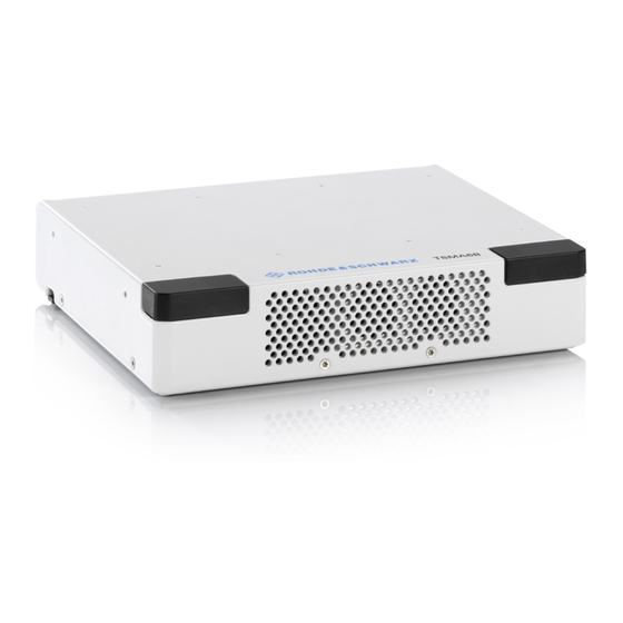
TSMA6B Rear panel view 3 Instrument tour 3.1 Front panel view The front panel of the R&S TSMA6B does not provide any connectors or control ele- ments for operation. Figure 3-1: R&S TSMA6B - Front Panel 3.2 Rear panel view The following figure provides an overview of the control elements and the connectors on the rear panel of the instrument. - Page 13 The SCAN port provides a high-speed 1 Gbit Ethernet interface with an RJ 45 connec- tor. It is used to connect the R&S TSMA6B to a separate R&S TSME6 as a second scanner. It can be used for MIMO scenarios and for increasing bandwidth and mea- surement rate.
- Page 14 Overall USB current (USB-C, USB 3.0 and USB 2.0): max. 3 A DC IN connector The DC IN connector is used to supply the R&S TSMA6B with DC power. A wide DC input range 11 V to 18 V / max. 7 A is supported.
-
Page 15: Removable Ssd Option (R&S Tsma6B-Beb)
32. RF IN connector The RF IN connector is the RF input of the R&S TSMA6B. The multi-band RF paddle antenna (700 MHz to 2.6 GHz), which is included in the shipment of R&S TSMA6B or any custom RF source is connected to this SMA connector. The maximum input power is +20 dBm/10 V DC. -
Page 16: Status Leds
Figure 3-3: R&S TSMA6B - removable disk option 1 = External enclosure with SSD hard disc 2 = USB connection between R&S TSMA6B and SSD hard disc For removing the external disk from the enclosure, see Chapter 5.9, "Using external SSD option (R&S... - Page 17 ® Instrument tour R&S TSMA6B Status LEDs Device Scanner [Mode] LED [Meas] LED [Pwr] LED [State]LED Comment green (CONT.) Power On / WLAN blue (CONT.) Power On / WLAN green (BLINKING red (Off-On < 5s => Off ) Scanner configura- rapidly =>...
-
Page 18: Option Concept
4.1 Software options (scanner) 4.1.1 Technology options Technology options allow the R&S TSMA6B to scan the input based on a specific tech- nology, for example, LTE. All technology options can be installed on the same instru- ment; the R&S TSMA6B can measure various technologies simultaneously. -
Page 19: Band Options
These configurations limit the number of bands that can be mea- sured in parallel. You can reconfigure the bands for each measurement as desired. Upgrade options are available to increase the bandwidth of the R&S TSMA6B from a limited number of bands to full bandwidth. - Page 20 ® Option concept R&S TSMA6B Software options (applications) For activating licenses via WIBU, refer to R&S ROMES4 - WIBU License Management manual. Accompanied with the hardlock dongle, a a license key file is offered. This license key file has to be copied as a post process after software installation (see "Install ROMES Option"...
-
Page 21: Preparing For Use
® Preparing for use R&S TSMA6B Unpacking the instrument 5 Preparing for use Risk of injury and instrument damage The instrument must be used in an appropriate manner to prevent electric shock, fire, personal injury, or damage. ● Do not open the instrument casing. -
Page 22: Connecting External Devices
Retain the original packing material. If the instrument needs to be transported or ship- ped later, you can use the material to protect the control elements and connectors. Accessories The following items are included with shipment of the R&S TSMA6B: ● 12 V DC power supply cable with a cigarette lighter connector ●... -
Page 23: Connecting Power Supply
Figure 3-2 - 11, 12) if you want to use local operation. (optional) 4. Connect a LAN cable to the LAN port if you want to use the R&S TSMA6B via Remote Desktop or as distributed system (optional). (See Figure 3-2 - 12.) -
Page 24: Connecting An Ac Power Supply
Figure 5-1: Supplied power cable with cigarette lighter adapter 5.3.2 Connecting an AC power supply To operate the R&S TSMA6B with an AC power supply, connect the DC IN connector with the AC power supply (R&S TSMA6B-Z1, R&S No. 4901.0550.02). -
Page 25: Connecting The R&S Tsma6B-Bp
When the R&S TSMA6B is switched off, remove the batteries from R&S TSMA6B-BP to prevent discharge. Risk of instrument damage If the R&S TSMA6B is connected with a R&S TSMA6B-BP, DC power must be connec- ted to the R&S TSMA6B-BP. Do not connect the DC power to the R&S TSMA6B. - Page 26 Figure 5-4: Battery orientation Note: The R&S TSMA6B may be used only with closed battery cover. 2. Remove the cover cap from the docking connector of the R&S TSMA6B. 3. Attach the R&S TSMA6B with the bottom side (see Figure 5-6) on top of the R&S...
- Page 27 *On delivery the power connector is protected by a cover cap. 4. Set the R&S TSMA6B vertically on top of the R&S TSMA6B-BP (1). 5. Slide the R&S TSMA6B horizontally (2) until it engages in the mechanical connec- tors on top of the R&S TSMA6B-BP. (Noticeable by a "click" sound.)
-
Page 28: Switching On R&S Tsma6B
3 = Power Connection established The power-up behavior after connecting the R&S TSMA6B-BP (including charged batteries or connected to an external DC power supply) with the R&S TSMA6B depends on the system settings on the R&S TSMA6B (see Chapter A.2.1.2, "Power",... - Page 29 ® Preparing for use R&S TSMA6B Connecting with R&S TSMA6B WLAN access point 2. Select the correct WLAN (in this example: TSMA6-101084). 3. Select "Connect automatically" and click "Connect". 4. Select "Connect using a security key instead". User Manual 4901.4026.02 ─ 01...
- Page 30 ® Preparing for use R&S TSMA6B Connecting with R&S TSMA6B WLAN access point 5. Enter the network security key and click "Next". Default security key: instrument User Manual 4901.4026.02 ─ 01...
-
Page 31: Connecting Usb To Lan Adapter Tspc-U2L2 / Tspc-Usl
® Preparing for use R&S TSMA6B Connecting USB to LAN adapter TSPC-U2L2 / TSPC-USL The connection to the WLAN access point is established. 5.6 Connecting USB to LAN adapter TSPC-U2L2 / TSPC- Currently following LAN adapters are available. ● Dual Gbit LAN port adapter TSPC-U2L2 ●... -
Page 32: Connecting Test Mobile Phones
"GPS Ant." on page 14) of the R&S TSMA6B. 1. Mount the R&S TSMA6B device fixed to the frame of a car. 2. Power on the R&S TSMA6B device. 3. Activate "Dead Reckoning" in the used software (for details, refer to R&S ROMES, R&S NESTOR or R&S ViCom documentation). -
Page 33: Using External Ssd Option (R&S Tsma6B-Beb)
Correct connection between R&S TSMA6B and SSD The option is pre-assembled and can only be ordered from the factory. For the USB connection between the R&S TSMA6B and the SSD hard disc, check that only the USB 3.0 port as shown in Figure 5-8 is used. - Page 34 ® Preparing for use R&S TSMA6B Using external SSD option (R&S TSMA6B-BEB) Figure 5-9: Remove external disk 1 = Tab 2 = Direction to remove external disk User Manual 4901.4026.02 ─ 01...
-
Page 35: Configuring The R&S Tsma6B
37). 6.2.1 Using the R&S TSMA6B web GUI The R&S TSMA6B web GUI gives the user full access to control and measure with the R&S TSMA6B. Following tasks can be done: ● Recall of system information / hardware software versions / IP settings ●... - Page 36 1. Connect the R&S TSMA6B LAN socket with an RJ45 cable to the LAN. 2. By default the R&S TSMA6B is configured to use DHCP and no static IP address is configured. The R&S TSMA6B shows the IP address in the local web-GUI (see "Using the local web GUI"...
-
Page 37: Using A Remote Desktop Connection
LAN: IP address of the R&S TSMA6B NOTE: If you connect the R&S TSMA6B LAN interface with a PC via LAN cable, the IP addresses are negotiated automatically by default. The IP address of the R&S TSMA6B can be read from the local web GUI (seeChapter 6.2.1,... - Page 38 R&S TSMA6B Accessing the R&S TSMA6B 6. Click "Connect". 7. Enter the password (default: 894129) and click "OK". 8. The remote desktop connection is established. The R&S TSMA6B can be controlled from the remote PC. User Manual 4901.4026.02 ─ 01...
-
Page 39: Selecting Measurement Mode
2. Start the R&S TSMA6B web GUI (see Chapter 6.2.1, "Using the R&S TSMA6B GUI", on page 35). 3. Select the measurement mode in the R&S TSMA6B web GUI, the modes are described in Chapter 6.3.1, "Measurement modes", on page 39. -
Page 40: Pc Mode
A Remote ViCom client application needs to be installed on the handheld device for this purpose. The connection between the Remote ViCom server on the R&S TSMA6B and the cli- ent application (Remote ViCom client) on the handheld device can be realized via ®... -
Page 41: Qualipoc Mode
(see Figure 6-7). ® To use the R&S TSMA6B with QualiPoc , the following steps must be performed. 1. Turn on the R&S TSMA6B scanner. 2. In the web-GUI, set the "Mode of Operation" to "QualiPoc" and press "Submit". - Page 42 TSMA6B Selecting measurement mode Figure 6-2: Scan for NCM 7. Touch "[Disconnected]", touch the TSMA6B scanner in the list, for example, "TSMA6B-900012", and then touch "OK" to accept the pairing request. Figure 6-3: Pair NCM Figure 6-4: Bluetooth pairing request 8.
-
Page 43: Nestor And Nestor Probe Mode
The NESTOR UI engine and the NESTOR measurement engine are hosted on the R&S TSMA6B. ● NESTOR probe mode The R&S TSMA6B hosts only the NESTOR measurement engine. The NESTOR UI engine is hosted on a remote PC connected via LAN/WLAN with the R&S TSMA6B. Prerequisites ●... - Page 44 3. Select a scenario ("Monitoring" or "Cellular Network Analysis"). 4. Press "Submit". The R&S TSMA6B is switched into "NESTOR" mode. In the status bar, the entry is "Changing mode of operation in progress...". The mode switch is finished when the status bar indicates "No error". The scanner state LED starts blinking rapidly.
-
Page 45: Smartone Mode
1. On the "Mode" tab, select "NESTOR Probe" mode. 2. Press "Submit". The R&S TSMA6B is switched into "NESTOR Probe" mode. In the status bar, the entry is "Changing mode of operation in progress...". The mode switch is finished when the status bar indicates "No error". The scanner state LED starts blinking rapidly. -
Page 46: Scanner Mode
R&S SmartONE. 6.3.1.6 Scanner mode You can use the R&S TSMA6B as scanner only. In this case, the R&S TSMA6B behaves like a R&S TSME6. The internal CPU is not powered, only the scanner is switched on. Scanner mode To use the R&S TSMA6B in scanner mode, proceed as follows. - Page 47 2. Switch off the R&S TSMA6B. 3. Then switch the R&S TSMA6B on again. The R&S TSMA6B is in scanner mode and can be accessed via the LAN port (2) with the IP address 192.168.0.2 The Status LED "Mode" (see...
-
Page 48: Importing Workspace Files (Nestor, Romes)
Note: The target directory for file upload depends on the selected mode. The men- tioned directory is only valid in ROMES mode. ® 6.5 Pairing Bluetooth devices To pair the R&S TSMA6B with a remote device, the following steps must be performed. User Manual 4901.4026.02 ─ 01... - Page 49 R&S TSMA6B", on page 119. 4. In the R&S TSMA6B web GUI, click "Refresh Device List". The status text shows the following: "Refreshing device list in progress". Wait until "No Error" is shown. 5. Click the arrow next to the "Refresh Device List" button and open the Bluetooth adapter list box 6.
-
Page 50: Changing Keyboard Language
Changing keyboard language 6.6 Changing keyboard language ® By default, the R&S TSMA6B is delivered with the English version of Windows 10 and it supports the English keyboard. To use the german keyboard (or any other one), pro- ceed as follows. -
Page 51: Verify Virtual Memory Settings
6. After successfully adding the language, it should be listed as selectable language. 7. Change the keyboard language via windows taskbar. 6.7 Verify virtual memory settings To enable virtual memory on the R&S TSMA6B, perform the following steps: 1. Open "Settings". User Manual 4901.4026.02 ─ 01... - Page 52 ® Configuring the R&S TSMA6B R&S TSMA6B Verify virtual memory settings 2. In the "Settings", select "System". User Manual 4901.4026.02 ─ 01...
- Page 53 ® Configuring the R&S TSMA6B R&S TSMA6B Verify virtual memory settings 3. In "Systems", select "About". User Manual 4901.4026.02 ─ 01...
- Page 54 ® Configuring the R&S TSMA6B R&S TSMA6B Verify virtual memory settings 4. Select "System info". 5. Select "Advanced System Settings". 6. Select the tab "Advanced". 7. Select "Settings..." in the section "Performance". 8. Select the tab "Advanced". User Manual 4901.4026.02 ─ 01...
- Page 55 ® Configuring the R&S TSMA6B R&S TSMA6B Verify virtual memory settings 9. Select "Change..." in the section "Virtual memory". 10. Enable "Automatically manage paging file size for all devices". 11. Click "OK" to close the dialog. 12. Reboot the device.
-
Page 56: Connecting Multiple Tsmx Devices
7 Connecting multiple TSMx devices 7.1 Connecting R&S TSMA6B with R&S TSME6 The usage of the R&S TSME6 at the SCAN port of the R&S TSMA6B requires the R&S TSME6 base firmware version 05.08.xx.00. Update the R&S TSME6 to the corresponding firme version in "Section 0" on a sepa- rate PC before connecting it to the R&S TSMA6B. - Page 57 For the synchronization between R&S TSMA6B and R&S TSME6, you need the syn- chronization cable R&S TSME6-ZC2. For the DC power between R&S TSMA6B-BP and R&S TSME6, you need the power cable R&S TSMA6-BPPT. For the RF input connector, you need an antenna according to your needs.
-
Page 58: Connecting R&S Tsma6B With R&S Tsmexxdc
4 = RF: R&S TSMExxDC IF1 - R&S TSMA6B RF In For the synchronization between R&S TSMA6B and R&S TSMExxDC, you need the synchronization cable R&S TSME6-ZC2. For the DC power between R&S TSMA6B-BP and R&S TSME6, you need the power cable R&S TSMA6-BPPT. Using a R&S TSME30DC (see... -
Page 59: Connecting R&S Tsma6B With R&S Tsmexxdc + R&S Tsme6
For the DC power between R&S TSMA6B-BP and R&S TSME6 / R&S TSMExxDC, you need need two times the power cable R&S TSMA6-BPPT. Alternatively you can use the dual power cable R&S TSMA6-B2T. It connects via Aux1 of the R&S TSMA6B the R&S TSMExxDC and R&S TSME6. -
Page 60: Update And Restore
Open the Internet Explorer. The web GUI starts automatically. If not, enter the URL http://localhost into the browser. 8.2.2 Checking mode of operation To execute the setup on the R&S TSMA6B, the mode of operation has to be "PC Mode". 1. Open the R&S TSMA6B web GUI. Use one of the following options. - Page 61 Update and restore R&S TSMA6B Updating firmware/software/tools - general instructions TSMAx-xxxxxx = R&S TSMA6B host name This information can be found on a label at the bottom. ● Local Open the Internet Explorer. The web GUI should be loaded automatically. If not, enter the URL http://localhost into the browser.
-
Page 62: Local Execution Of The Setup File
1. Connect mouse and keyboard to USB ports and a monitor to the HDMI port. The setup file must be available on the R&S TSMA6B or on a USB stick. 2. Switch on the R&S TSMA6B via the power button. - Page 63 ® Update and restore R&S TSMA6B Updating firmware/software/tools - general instructions 7. In the License Agreement window, check "I accept the license agreement". 8. Click "Next>". 9. The package dialog lists all the available packages in the setup. Normally, you can skip this dialog without any changes.
- Page 64 ® Update and restore R&S TSMA6B Updating firmware/software/tools - general instructions 10. Press "Install >". The progress bar indicates the installation process. Note: Do not switch off or unplug from power while running firmware/software update. 11. The device will automatically reboot after the installation is complete.
-
Page 65: Remote Installation Of The Setup File
Chapter 6.3, "Selecting mea- surement mode", on page 39. The R&S TSMA6B is ready for operation. 8.2.4 Remote installation of the setup file 1. Copy the setup file (firmware TSMAx-Setup-<Version>.exe or software) into a temporary directory on the remote PC. - Page 66 Using LAN connection ● Connect the LAN port of the R&S TSMA6B with the host PC LAN port. The LAN port is marked with the LAN symbol. The default IP setting of this port is "DHCP client". For details on how to configure the remote PC, contact your network administrator.
- Page 67 All packages, which you need to install are already pre-selected. 6. Click "Next>". 7. After a while, all R&S TSMA6B devices in the network are listed in the "Device List" dialog. Devices are only listed, if the device is in "PC Mode" (see Chapter 8.2.2, "Checking...
-
Page 68: Local Installation Using A Usb Stick
8.2.5 Local installation using a USB stick The setup will be initiated via the web GUI of the R&S TSMA6B. In this case, the setup file must be available in the root directory of a USB stick, which is connected to the R&S TSMA6B. - Page 69 Chapter 8.2.1, "Calling R&S TSMA6B web GUI", on page 60). 5. Make sure, that the R&S TSMA6B is in "PC Mode". 6. In the R&S TSMAx web GUI, navigate to the menu "Update" and select the instal- lation file for one of the following.
- Page 70 10. When the installation of all firmware/software packages has finished, the R&S TSMA6B reboots. After reboot the firmware is running a selftest (Mode LED is blinking green). 11. Open the web GUI. After a while, the status text in the web GUI changes to No error.
-
Page 71: Firmware Update - Details
® Update and restore R&S TSMA6B Firmware update - details 13. To configure the required measurement mode, see Chapter 6.3, "Selecting mea- surement mode", on page 39. 8.3 Firmware update - details The following steps are only performed during firmware update, if the firmware pack- age contains a new mainboard firmware. -
Page 72: Software Update - Details
8.4.1 Remote ViCom Server software The Remote ViCom server (rViCom) is an additional software package for the R&S TSMA6B. The latest version of this package is pre-installed on any shipped R&S TSMA6B. An upgrade of the Remote ViCom package is only recommended when operating the R&S TSMA6B in "rViCom Server"... -
Page 73: Preparation
TSMA6B Software update - details The installed version of the Remote ViCom server on the R&S TSMA6B needs to match with the applied version of rViCom client API on the remote Android device. In cases of a client / server mismatch, there are the following possibilities: ●... -
Page 74: Vicom Server Remote Installation
® Update and restore R&S TSMA6B Software update - details 3. All subsequent steps are similar to local firmware installation, see Chapter 8.2.3, "Local execution of the setup file", on page 62, step 9 and following. Do not switch off or unplug from power while running firmware/software update. -
Page 75: Vicom Server Installation Using A Usb Stick
® Update and restore R&S TSMA6B Software update - details 3. All subsequent steps are similar to remote firmware installation, see Chapter 8.2.4, "Remote installation of the setup file", on page 65, step 4 and following. 8.4.1.4 ViCom server installation using a USB stick Follow the general instructions in Chapter 8.2.5, "Local installation using a USB... -
Page 76: R&S Nestor Software
® Update and restore R&S TSMA6B Software update - details 2. The following steps are similar to the installation using a USB stick, see Chap- ter 8.2.5, "Local installation using a USB stick", on page 68, step 8 step 8.4.2 R&S NESTOR software 8.4.2.1... -
Page 77: Nestor Remote Installation
® Update and restore R&S TSMA6B Software update - details 2. The "R&S Software Distributor" comes up. Select "Local Installation" and press "Next". 3. All subsequent steps are similar to local firmware installation, see Chapter 8.2.3, "Local execution of the setup file",... -
Page 78: Nestor Installation Using A Usb Stick
® Update and restore R&S TSMA6B Software update - details 3. All subsequent steps are similar to remote firmware installation, see Chapter 8.2.4, "Remote installation of the setup file", on page 65, step 4 and following. 8.4.2.4 NESTOR installation using a USB stick Follow the general instructions in Chapter 8.2.5, "Local installation using a USB... -
Page 79: R&S Smartone Setup (Smartbenchmarker, Romes, Qualipoc)
® Update and restore R&S TSMA6B Software update - details 2. The following steps are similar to the installation using a USB stick, see Chap- ter 8.2.5, "Local installation using a USB stick", on page 68, step 8 step 8.4.3 R&S SmartONE setup (SmartBenchmarker, ROMES, QualiPoc) It is recommended to install and use the Google Chrome™... -
Page 80: Preparation
® Update and restore R&S TSMA6B Software update - details 8.4.3.1 Preparation 1. Download the SmartONE setup file SmartONE_x.y.z.exe from the Rohde & Schwarz FTP server respectively SmartONE CD-ROM. 2. Choose the way of installation and follow the instructions how to prepare. - Page 81 ® Update and restore R&S TSMA6B Software update - details Initial starting of SmartONE Expert (R&S ROMES) 1. Install the option key (see Chapter 8.6.3, "Installation of SmartONE Expert (ROMES) options", on page 87). 2. If used, connect the hardlock to a USB port.
- Page 82 ® Update and restore R&S TSMA6B Software update - details 2. Press "OK". 3. In the "ROMESTecSelectorGUI" window, press "OK". The current installation is adapted according to your selection and the ROMES start process continues. 4. In the "User" window, check that the "User Level" is "Normal".
- Page 83 ® Update and restore R&S TSMA6B Software update - details 6. In the "Installation Check", select "Don't Ask again" and press "Continue". Initial starting of SmartONE Standard (R&S SmartBenchmarker) 1. Start the web GUI. 2. Navigate to "Configuration" > "System" > "Mode".
-
Page 84: Tsmetools Update
® Update and restore R&S TSMA6B TsmeTools update 8.5 TsmeTools update The setup file is named TSMAx-TsmeTools-v<x.y.z.z1>.exe (example: TSMAx-TsmeTools-v1.7.0.2.exe). 8.5.1 Preparation 1. Download the TsmeTools setup file TSMAx-TsmeTools-v<x.y.z.z1>.exe from https://www.rohde-schwarz.com/software/tsmx/. 2. Choose the way of installation and follow the instructions how to prepare. -
Page 85: Tsmetools Remote Installation
® Update and restore R&S TSMA6B TsmeTools update 3. All subsequent steps are similar to local firmware installation, see Chapter 8.2.3, "Local execution of the setup file", on page 62, step 9 and following. Do not switch off or unplug from power while running firmware/software update. -
Page 86: Options (Nestor, Tsma6B, Smartone Expert)
68, step 8 to . 8.6 Options (NESTOR, TSMA6B, SmartONE Expert) The device must be in the "PC Mode". Check it via the web GUI ("Overview" > "Mode of Operation"). To change the operation mode, see "Mode of Operation"... -
Page 87: Installation Of Tsma6B Options
Update and restore R&S TSMA6B Options (NESTOR, TSMA6B, SmartONE Expert) 1. Start the web GUI of the R&S TSMA6B. 2. Navigate to "Options" > "Install" Tab (see "Install NESTOR Options" on page 134). 3. Add the license key code of a specific NESTOR option in the field "Install NESTOR Options"... -
Page 88: User Backup And Restore
8.7.1 Backup To create a user backup, click the "User Backup" button in the web GUI "(System" > "Config" Tab), see "Backup TSMA6B System" on page 136. A backup of the system partition C:\ is created. If there is an already existing user backup, an acknowledgment dialog pops up. After confirmation this user backup will be overwritten. -
Page 89: Restore
The color of the LED depends on the state of the WLAN AP. During the backup, do not interrupt the procedure or disconnect the power supply. 8.7.2 Restore With the RESTORE button, it is possible to restore the system partition R&S TSMA6B to the user backup (see Chapter 8.7.1, "Backup",... -
Page 90: Usage Of The R&S Tsma6B Image Stick
7. After the reboot, check if a microcontroller flash is performed (LED blue/green). 8.8 Usage of the R&S TSMA6B Image Stick With the R&S TSMA6B image stick, you can capture images from and apply images to another R&S TSMA6B. ●... -
Page 91: Boot From The R&S Tsma6B Image Stick
● bootmgr.efi When the creation of the image stick has finished, you can boot the R&S TSMA6B from this stick. 8.8.2 Boot from the R&S TSMA6B Image Stick To boot from the R&S TSMA6B image stick, proceed as follows. - Page 92 R&S TSMA6B Usage of the R&S TSMA6B Image Stick NOTE: No image files may be present on the R&S TSMA6B image stick in the direc- tory Device/Images. Otherwise, capturing the image from a R&S TSMA6B master device is not possible.
-
Page 93: Apply An Image To A R&S Tsma6B
8.8.4 Apply an Image to a R&S TSMA6B To apply an image to a R&S TSMA6B, the following files must be available in the direc- tory Device/Images on the R&S TSMA6B image stick. - Page 94 2. In the main menu, press "Apply Image". The apply process starts automatically. The image files from the R&S TSMA6B master device are transferred to the R&S TSMA6B target device and removed from the R&S TSMA6B image stick. 3. After the apply process has finished, the message "Operation successfully done."...
- Page 95 ® Update and restore R&S TSMA6B Usage of the R&S TSMA6B Image Stick 4. Press "OK". 5. Remove the R&S TSMA6B image stick. 6. Press "Reboot". The R&S TSMA6B reboots from the deployed image. User Manual 4901.4026.02 ─ 01...
-
Page 96: Troubleshooting
Evaluate selftest file....................97 ● Verify scanner link / recall device info using TsmeDeviceManager......97 ● R&S TSMA6B automatically switches off after power on........101 ● Scanner is not found from software (R&S ROMES, R&S NESTOR)....102 ● Verify scanner connection LAN settings..............105... -
Page 97: Evaluate Selftest File
® Troubleshooting R&S TSMA6B Verify scanner link / recall device info using TsmeDeviceManager 9.2 Evaluate selftest file ● Path: C:\ProgramData\Rohde-Schwarz\TSMA\Selftestresults ● Filename: Selftestresult.txt Entries in the Selftestresult.txt are created during the boot process of the device and every 5 minutes. -
Page 98: Obtaining Device Information - "Device Info
TSMA6B Verify scanner link / recall device info using TsmeDeviceManager If the connection to an R&S TSMA6B could not established correctly, (for example due to a mismatch of the scanner link IP configuration), only limited information is dis- played. In this case, no information about installed options is available. -
Page 99: Device Analysis Output
® Troubleshooting R&S TSMA6B Verify scanner link / recall device info using TsmeDeviceManager Table 9-1: R&S TSMA6B device information Label Description Device Device Type Type of device (TSME family, TSMA family) Material Number Order number of the R&S TSMA6B Variant Number... -
Page 100: Verify Installed License Keys
- must be solved before further operation In case measurement problems occur with the R&S TSMA6B, check the "Device Analysis Output" table for any errors that may have been detected. If available, a repair function is provided. -
Page 101: R&S Tsma6B Automatically Switches Off After Power On
Connect DC supply to the R&S TSMA6B battery pack unit and charge the bat- teries inside the bay. Keep the R&S TSMA6B switched off. 4. Connect DC supply to the R&S TSMA6B battery pack unit and check in the web GUI the "Shutdown Settings". -
Page 102: Scanner Is Not Found From Software (R&S Romes, R&S Nestor)
® Troubleshooting R&S TSMA6B Scanner is not found from software (R&S ROMES, R&S NESTOR) ● If not enabled, contact R&S support. 9.5 Scanner is not found from software (R&S ROMES, R&S NESTOR) To check if the scanner unit is working properly, perform the following steps. - Page 103 If an error is listed, check the error type. ● If no error is listed, continue with step 3 3. Start the web GUI (see Chapter 6.2.1, "Using the R&S TSMA6B web GUI", on page 35). Check "Mode of Operation" and "IP Settings". ●...
- Page 104 Scanner is not found from software (R&S ROMES, R&S NESTOR) ● If the "Mode of Operation" != "PC Mode", switch mode to "PC Mode". Restart the R&S TSMA6B via web GUI and check the LEDs, see step ● If the IP address of the "SCAN Port (int)" = "192.168.0.1", continue with step ●...
-
Page 105: Verify Scanner Connection Lan Settings
Verify scanner connection LAN settings 7. Check in the "Info" tab, if any device is available. ● If the R&S TSMA6B device is found, check the "Device Analysis Output". ● If the R&S TSMA6B device is not found, contact the R&S support. -
Page 106: No Rf / Gps Data
® Troubleshooting R&S TSMA6B No RF / GPS data Figure 9-3: TSMA6B scanner connection 2. Double-click the "TSMA6B Scanner Connection Int " entry and verify the following settings. ● IP address: 192.168.0.1 (static IP address) ● "Jumbo Packet": 9014 Bytes 9.7 No RF / GPS data... - Page 107 ® Troubleshooting R&S TSMA6B No RF / GPS data Figure 9-4: RF antenna connector 1 = RF port 2. Check if the GPS antenna is connected to GPS antenna input. Figure 9-5: GPS antenna connector 1 = GPS antenna connector Note: Only use the GPS antenna included in the scope of delivery.
-
Page 108: No Remote Access Via Lan Port
TSMA6B No remote access via LAN port 9.8 No remote access via LAN port If the R&S TSMA6B could not be accessed for remote control or remote desktop ses- sion via the LAN port, check following issues: Optical Check 1. Check on the rear panel, if the LAN cable is connected to the remote control LAN... - Page 109 Figure 9-7: Web GUI - LAN Connection Ping Command The ping command must be executed from the Windows command prompt on the host PC. 1. Use the IP address displayed in the R&S TSMA6B web GUI (see Figure 9-6). User Manual 4901.4026.02 ─ 01...
- Page 110 2. Start the ping command. Type in the command-line window ping <IP address of the remote port of the R&S TSMA6B (LAN)> and wait for the answer. If the R&S TSMA6B does not answer, contact the system administrator or the R&S support. Example: C:\>ping 192.167.0.10...
-
Page 111: Wlan Access Point Not Detected By External Pc, Mobile Or Tablet
With the first R&S TSMA6B devices shipped, the WLAN module is configured to use the 2.4 GHz and 5 GHz band. In environments with high traffic on the 2.4 GHz band, the R&S TSMA6B access point sometimes switches into the 5 GHz band after power-up. The effect is that notebooks / PCs / handheld devices with a 2.4 GHz limited WLAN module could no longer detect... - Page 112 Under Windows, navigate to "Settings" > "Network & Internet" > "Network & Shar- ing Center" > "Change Adapter Settings" Check for the following entries: ● "TSMA6B WLAN AP" ● "TSMA6B WLAN Connection" If the entries are available, continue with step If the entries are not available, reset a factory backup (see Chapter 8.7.3, "Restore...
- Page 113 TSMA6B WLAN access point not detected by external PC, mobile or tablet 6. Verify driver settings. Right click on "TSMA6B WLAN Connection" and open "Properties". Click "Configure" and select tab "Advanced". Check for the following setting: "802.11a/b/g" = "2.4GHz 802.11b/g"...
-
Page 114: Web Gui Not Accessible Via Wlan
TSMA6B Web GUI not accessible via WLAN 9.10 Web GUI not accessible via WLAN If the R&S TSMA6B web GUI is not accessible, perform the following steps to solve the problem. 1. Check if the WLAN AP is activated. ●... -
Page 115: Web Gui Locally Not Accessible
9.11 Web GUI locally not accessible Open the web GUI locally. Start the Internet Explorer and enter the following URL to open the R&S TSMA6B web GUI . http://localhost 1. Check the URL in the browser dialog. Following URL must be displayed: http://localhost/TSMA/Html/overview.php... - Page 116 ● R&S TSMA Monitoring Application running? ● R&S WebServer running? Figure 9-9: R&S TSMA6B Services If both services are running, continue with step 3. Start the services, that are not running. a) Select the service to be started. b) Open the context menu with a right-mouse click.
-
Page 117: Slow/Instable Wlan Connection
R&S TSMA6B Slow/Instable WLAN connection 4. Try again to start the web GUI locally on the R&S TSMA6B via Internet Explorer. If the web GUI cannot be started, a complete restore must be performed (see Chapter 8.7, "User backup and restore",... - Page 118 ® Troubleshooting R&S TSMA6B Slow/Instable WLAN connection 4. Select tab "Advanced". 5. Change the property "802.11a/b/g Wireless Mode" to "4. 2.4GHz 802.11 b/g". 6. Change the property "802.11n/ac/ax Wireless Mode" to "802.11n". User Manual 4901.4026.02 ─ 01...
-
Page 119: Bluetooth ® Device Not Detected By R&S Tsma6B
The visibility of an Android device with firmware version ≥5.0 cannot be changed. The mobile (tablet) is only visible to other devices when the "Bluetooth Properties" window is open. If you are controlling the R&S TSMA6B web GUI with the mobile and also want to cou- ® ple the devices via Bluetooth , then you have to perform following steps. - Page 120 TSMA6B ® Bluetooth device not detected by R&S TSMA6B 3. After choosing the R&S TSMA6B, you receive a "Bluetooth pairing request". Click "OK". 4. Open the R&S TSMA6B web GUI and navigate to "Configuration" > "Connectivity" > "Bluetooth". 5. Execute "Refresh Device List".
-
Page 121: Contacting Customer Support
® Troubleshooting R&S TSMA6B Contacting Customer Support 7. Select the mobile device and press "Connect" for coupling the devices. 9.14 Contacting Customer Support Technical support – where and when you need it For quick, expert help with any Rohde & Schwarz product, contact our customer sup- port center. -
Page 122: Annex
The "System" window consists of the following tabs. ● Overview....................... 122 ● Settings......................124 ● Info......................... 124 A.1.1 Overview The "Overview" tab displays the following basic settings of the R&S TSMA6B. Device Info........................123 └ Type......................123 └ Material No....................123 └... - Page 123 Serial No. ← Device Info Serial number of the device Computer Name ← Device Info Computer name of the R&S TSMA6B (read-only). The name consists of a fixed part (TSMA6B) and a variable part (serial number). Example: R&S TSMA6B-<Serial Number>...
-
Page 124: Ip Settings
Battery Life Time ← Battery Info Estimated remaining battery life time. Mainboard Temperature ← Battery Info Current temperature of the mainboard. A.1.2 IP Settings The "IP Settings" tab displays the IP addresses of the R&S TSMA6B. LAN..........................124 SCAN (Int.)........................124 EXT1........................124 WLAN AP (Overview)....................124... - Page 125 ® Usage of the Web GUI R&S TSMA6B Home └ TCXO Date....................125 Module Info......................... 125 └ Controller Board....................125 └ Board.......................126 └ Mainboard..................... 126 └ Batterypack....................126 Down Converter Info....................126 └ Available Config.................... 126 └ Used Config....................126 └...
-
Page 126: Configuration
® Usage of the Web GUI R&S TSMA6B Configuration RF Board ← Module Info Serial number and product change index of the RF board. Mainboard ← Module Info Serial number and product change index of the main board. Batterypack ← Module Info Serial number and product change index of the battery pack module (TSMA6-BP). -
Page 127: Mode
The R&S TSMA6B remembers the last state before the DC power was removed. When DC power is applied again at the DC IN connector of the R&S TSMA6B or at the DC IN connector of a connected R&S TSMA6B battery pack, the power state before power removal is recovered. -
Page 128: Speaker
Battery Pack. Auto Power Off ← Shutdown Settings When activated, the R&S TSMA6B is powered off automatically, if the DC IN power is removed from the connected R&S TSMA6B Battery Pack. The time delay for powering off can be set manually (default 30s). -
Page 129: Connectivity
● LAN........................131 ● EXT1......................132 A.2.2.1 Bluetooth The "Bluetooth" tab is used to configure the settings of the R&S TSMA6B Bluetooth adapter. As well this tab is used for pairing with an external BT device. Bluetooth Connection....................129 └ Status (Bluetooth).................. -
Page 130: Wlan Ap
The IP address can be assigned automatically via DHCP ("DHCP") or manually as fixed IP address ("Static"). IP Address (WLAN Client) ← WLAN Adapter Specify the IP address of the R&S TSMA6B Subnet Mask (WLAN Client) ← WLAN Adapter Specify the subnet mask for the R&S TSMA6B Default Gateway (WLAN Client) ←... -
Page 131: Lan
The IP address can be assigned automatically via DHCP ("DHCP") or manually as fixed IP address ("Static"). IP Address (LAN) ← LAN Connection Specify the IP address of the R&S TSMA6B. Subnet Mask (LAN) ← LAN Connection Specify the subnet mask for the R&S TSMA6B. -
Page 132: Lan Ext1
Specify the DNS server. It is possible to specify a primary and a secondary DNS server. A.3 File Transfer The "File Transfer" window offers the following functions: ● Uploads and downloads of files to/from the R&S TSMA6B. ● Download of the Vicom sample application to an Android device. File Transfer........................ 133 └... -
Page 133: Options
R&S TSMA6B (D:\Upload). Note: The maximum file size for the upload is 2048 MB. Download ← File Transfer Specifies the measurement data file to be transferred from the R&S TSMA6B (D:\Download) to a connected device. User-defined Upload ← File Transfer Specifies the file (e.g. -
Page 134: Install
Start and expiration date of installed temporary license key Option Index Index number of the installed license key A.4.2 Install The "Install" tab is used to install various license key files on the R&S TSMA6B. Install NESTOR Options....................134 Install Scanner Options.................... -
Page 135: Update
R&S TSMA6B Update A.5 Update The "Update" window allows to select and update the TSMA6B software and additional software components. Prerequisites for a Firmware/Software Update ● The setup file must be located in the root directory of the data stick. -
Page 136: Backup
Select the setup file from the "Select TsmeTools Setup File" box and click "Update TsmeTools". The setup is started. The progress can be monitored in the status line of the web GUI. A.6 Backup The "Backup" window allows to create a backup of the R&S TSMA6B system. Backup TSMA6B System....................136 Backup TSMA6B System Click "Backup"... -
Page 137: Help
® Usage of the Web GUI R&S TSMA6B Help Click "OK" to reboot the scanner unit of the R&S TSMA6B. A.8 Help The "Help" window displays the online help system of the R&S TSMA6B. User Manual 4901.4026.02 ─ 01... -
Page 138: B Introduction To Remote Vicom Sample App
Remote rViCom Server on the R&S TSMA6B (default) ● An installed Sample App on the Android device The version of the rViCom server on the R&S TSMA6B must match the version of the Sample App on the Android device. B.2.2 Preparation Before starting a scan or test, it is necessary to make sure that a connection can be established. -
Page 139: Usage
Start the Sample App on the Android device. B.3.1.1 Connection Type Selection To connect to the R&S TSMA6B Remote rViCom Server, it is either possible to use a WLAN connection or a Bluetooth connection. The selection of the connection type depends on the measurement task (see Chap- ter B.3.1, "Connection... - Page 140 ® Introduction to Remote ViCom Sample App R&S TSMA6B Usage 3. If a server is found, the server will be connected and the name of the server is dis- played. Figure B-3: Successful Server Discovery 4. Choose the server. If a Remote rViCom server connection could be established, the "Choose scan type"...
-
Page 141: Gsm Rssi Scan
® Introduction to Remote ViCom Sample App R&S TSMA6B Usage Provides a spectrum analysis by selecting the frequency range The RAN technology for which a scan should be performed has to be selected. The selection of the technologies is described in the following chapters. -
Page 142: Wcdma Top-N Pilot Scan
® Introduction to Remote ViCom Sample App R&S TSMA6B Usage Figure B-6: GSM Scan Result View Below the graph the measurement preferences and the status are displayed. Parameters Displays the configured preferences for the GSM RSSI scan. Status Displays the measurement duration and the measurement rate. The status button dis- plays the following colored states. -
Page 143: Wcdma Top-N Pilot Scan Results
® Introduction to Remote ViCom Sample App R&S TSMA6B Usage Figure B-7: Setting the WCDMA Preferences 2. If necessary, change the UARFCN according to your needs. Note: Due to processing issues, it is not possible to select more than one UARFCN. -
Page 144: Lte Top Signal Scan
® Introduction to Remote ViCom Sample App R&S TSMA6B Usage Status Displays the measurement duration and the measurement rate. The status button dis- plays the following colored states. ● Green The measurement is running and measurement data are received. ●... -
Page 145: Lte Top Signal Scan Results
® Introduction to Remote ViCom Sample App R&S TSMA6B Usage B.3.4.2 LTE Top Signal Scan Results The LTE scan result graph displays one column for each PCI found by the measure- ment. The height of a column represents the PBCH RSRP value (in dBm). -
Page 146: Throughput Results
® Introduction to Remote ViCom Sample App R&S TSMA6B Usage 1. Specify the parameter "Buffer size (in Byte)". The default buffer size is 20480 bytes. Figure B-11: Throughput Preferences 2. Click "Start Test" to start the throughput test. For WLAN, the optimal buffer size varies between 950.000 byte and 1.000.000 byte. -
Page 147: Rf Power Scan
® Introduction to Remote ViCom Sample App R&S TSMA6B Usage Results ● Max. Through Displays the maximum throughput ● Ave. Through Displays the average throughput ● Last Through Displays the current throughput ► To stop the scan, use "Stop scan" in the menu inflator in the top right corner. - Page 148 ® Introduction to Remote ViCom Sample App R&S TSMA6B Usage Figure B-14: RF Power Scan Results Below the graph the measurement preferences and the status are displayed. Parameters ● Start Displays the start frequency ● Displays the end frequency Status Displays the measurement duration and the measurement rate.
-
Page 149: C Managing Scanner Device With R&S Tsmedevicemanger
® Managing Scanner Device with R&S TsmeDeviceManger R&S TSMA6B Installing and Managing Software License Keys - "Options" C Managing Scanner Device with R&S Tsme- DeviceManger The "R&S TSME Device Manager" is a configuration software tool for scanners of the ®... - Page 150 ® Managing Scanner Device with R&S TsmeDeviceManger R&S TSMA6B Installing and Managing Software License Keys - "Options" Figure C-1: Tab "Options" For each option, the following information is displayed: Information for options that are no longer valid because their expiry date has passed are listed as "Inactive Options".
-
Page 151: Configuring Measurement Bands - "Band Configuration
Enter the 30-digit key code from the "License Keys List" in the "Key" field. Alternatively, if available, copy the key code from the supplied PDF license key file and paste it in the "Key" field. To install the software license key on the currently selected R&S TSMA6B, select the "Install" button (see Figure C-1). - Page 152 The band configuration is defined in the "Band Configuration" tab of the "R&S TSME Device Manager". Select the bands that are to be scanned by the R&S TSMA6B in the "Band Table". Which bands are available is independent of the installed technology options; all instal- led technologies can be scanned in all configured bands at the same time.
-
Page 153: Obtaining Firmware And Correction Data Updates - "Updates
Red dates indicate the changes recently made, while green dates indicate possible changes left. Applying band configuration changes Changes to the band configuration are only applied to the R&S TSMA6B when you select the "Accept Band Changes" button in the "Band Configuration" tab of the "R&S TSME Device Manager". -
Page 154: Aligning R&S Tsma6B Manually - "Self Alignment
TSMA6B Aligning R&S TSMA6B Manually - "Self Alignment" You can update the basic FPGA or the correction data on your R&S TSMA6B directly from the "R&S TSME Device Manager", in the "Update" tab. The currently installed ver- sions and the newest supported version (of the FPGA) or the minimum recommended version (of the correction data) are indicated. -
Page 155: Configuring Downconverter R&S Tsme30Dc/ Tsme44Dc - "Downconverter Configuration
® Managing Scanner Device with R&S TsmeDeviceManger R&S TSMA6B Configuring Downconverter R&S TSME30DC/TSME44DC - "Downconverter Configuration" Figure C-4: Tab "Self Alignment" Start Self Alignment To start the self-alignment manually, select the "Start Self Alignment" button in the "Self Alignment" tab of the "R&S TSME Device Manager". - Page 156 ® Managing Scanner Device with R&S TsmeDeviceManger R&S TSMA6B Configuring Downconverter R&S TSME30DC/TSME44DC - "Downconverter Configuration" Figure C-5: Tab "Downconverter Configuration" IF Output Receiver Configuration Specify the configuration of the IF output connectors of the R&S TSME30DC/ TSME44DC. RF Input Antenna Configuration ●...
-
Page 157: Index
® Index R&S TSMA6B Index Band Options R&S TSMA6B Option concept .......... 18 Available ..............19 Release notes ..............9 Brochures ................9 Remote rViCom Requirements ............138 Usage ............... 139 Remote ViCom ..............138 Customer support ............121 Removable disk option ............15 RF Power Scan ...............
Need help?
Do you have a question about the TSMA6B and is the answer not in the manual?
Questions and answers