R&S TSMA6 User Manual
Autonomous mobile network scanner
Hide thumbs
Also See for TSMA6:
- User manual (190 pages) ,
- Getting started (51 pages) ,
- Manual (10 pages)
Table of Contents
Advertisement
Quick Links
Advertisement
Table of Contents

Related Manuals for R&S TSMA6


Summary of Contents for R&S TSMA6
- Page 1 ® R&S TSMA6 Autonomous Mobile Network Scanner User Manual (a0ÞÇ2) 4900805702...
- Page 2 Rohde & Schwarz GmbH & Co. KG. Trade names are trademarks of the owners. ® 4900.8057.02 | Version 01 | R&S TSMA6 Throughout this manual, products from Rohde & Schwarz are indicated without the ® symbol , e.g. R&S ® TSMA6 is indicated as R&S TSMA6.
- Page 3 Safety Instructions Instrucciones de seguridad Sicherheitshinweise Consignes de sécurité Risk of injury and instrument damage The instrument must be used in an appropriate manner to prevent electric shock, fire, personal injury or instrument damage. ● Do not open the instrument casing. ●...
- Page 4 Gefahr von Verletzungen und Schäden am Gerät Betreiben Sie das Gerät immer ordnungsgemäß, um elektrischen Schlag, Brand, Verletzungen von Personen oder Geräteschäden zu verhindern. ● Öffnen Sie das Gerätegehäuse nicht. ● Lesen und beachten Sie die "Grundlegenden Sicherheitshinweise", die als gedruckte Broschüre dem Gerät beiliegen. ●...
-
Page 5: Table Of Contents
Connecting to a Vehicle DC Power Supply..............19 5.3.2 Connecting an AC Power Supply..................19 5.3.3 Connecting the R&S TSMA6-BP Battery Pack Unit............20 Connecting Test Mobile Phones................22 Enabling Untethered Dead Reckoning ..............22 6 Configuring the R&S TSMA6...............24 Accessing the R&S TSMA6..................24 6.1.1... - Page 6 7.5.1 Backup.......................... 47 7.5.2 Restore..........................47 Master Image....................... 48 7.6.1 Prepare a TSMA6 Image Stick / TSMA6 Recovery Stick..........49 7.6.1.1 USB Stick Preparation....................49 7.6.1.2 Copy File Contents on the USB Stick (Image Stick)............. 52 7.6.1.3 Copy File Contents on the USB Stick (Recovery Stick)..........52 7.6.2...
- Page 7 Deploy a TSMA6 image from a TSMA6 Recovery Stick..........58 8 Troubleshooting................... 60 No Remote Access to the R&S TSMA6 via LAN Port..........60 Scanner Is Not Found from Software (R&S ROMES, R&S NESTOR)..... 63 Verify Scanner Connection LAN Settings..............65 No Navigation Data in R&S ROMES / R&S NESTOR..........66...
- Page 8 ® Contents R&S TSMA6 Backup......................... 82 Restart..........................82 Help..........................83 B Introduction to Remote ViCom Sample App........84 Overview........................84 Requirements......................84 B.2.1 General Requirements....................84 B.2.2 Preparation........................84 Usage........................... 85 B.3.1 Connection Establishment.................... 85 B.3.1.1 Connection Type Selection................... 85 B.3.1.2 Server Discovery......................85 B.3.2...
-
Page 9: Preface
1.2.1 Getting Started Manual Introduces the R&S TSMA6 and describes how to set up and start working with the product. Includes basic operations, typical measurement examples, and general infor- mation, e.g. safety instructions, etc. A printed version is delivered with the instrument. -
Page 10: User Manuals And Help
The printed document is delivered with the instrument. 1.2.4 Data Sheets and Brochures The data sheet contains the technical specifications of the R&S TSMA6. It also lists the firmware applications and their order numbers, and optional accessories. The brochure provides an overview of the instrument and deals with the specific char- acteristics. -
Page 11: Key Features
The R&S TSMA6 enhances such solutions, providing the user with accurate insight into the RF environment. The R&S TSMA6 combines the technology of the R&S TSME6 ultra-compact drive test scanner with a high-performance Intel processor. The scanner can run PC-based drive test software, and smartphones can be connected via USB. -
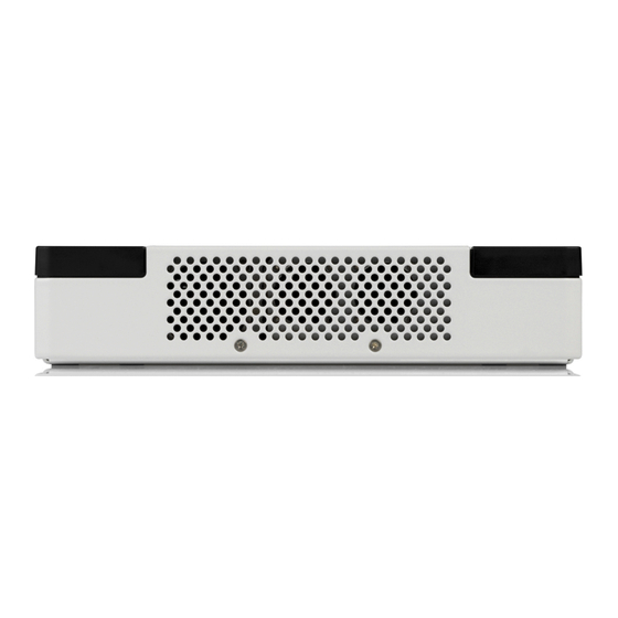
Page 12: Instrument Tour
TSMA6 Rear Panel View 3 Instrument Tour 3.1 Front Panel View The front panel of the R&S TSMA6 does not provide any connectors or control ele- ments for operation. Figure 3-1: R&S TSMA6 - Front Panel 3.2 Rear Panel View The following figure provides an overview of the control elements and the connectors on the rear panel of the instrument. - Page 13 The LAN connector provides a high-speed 1 Gbit Ethernet interface with an RJ 45 con- nector. It is used to connect the R&S TSMA6 to a separate R&S TSME6 as a second scanner. It can be used for MIMO scenarios and for increasing bandwidth and mea- surement rate.
- Page 14 ® Instrument Tour R&S TSMA6 Rear Panel View Indicates the state of the scanner component ● [Mode] Indicates the device status ● [Meas] Indicates the state of the SW application Device Scanner [Mode] LED [Meas] LED [Pwr] LED [State]LED Comment...
- Page 15 All user data since last backup is lost. DC IN Connector The DC IN connector is used to supply the R&S TSMA6 with DC power. A wide DC input range 11 V to 18 V / max. 7 A is supported.
- Page 16 1600 pixel) RF IN Connector The RF IN connector is the RF input of the R&S TSMA6. The multi-band RF paddle antenna (700 MHz to 2.6 GHz), which is included in the shipment of R&S TSMA6 or any custom RF source is connected to this SMA connector. The maximum input power is +20 dBm/10 V DC.
-
Page 17: S Tsma6 Option Concept
TSMA6 Technology Options 4 R&S TSMA6 Option Concept The R&S TSMA6 scanner consists of the R&S TSMA6 hardware and a set of (speci- fied) technology and band options when it comes from the factory. 4.1 Technology Options Technology options allow the R&S TSMA6 to scan the input based on a specific tech- nology, for example, LTE. -
Page 18: Band Options
A later installation of additional R&S NESTOR options can be done via the R&S TSMA6 web-GUI or via the License Key Manager. In this case, you have to order option-specific NESTOR license keys. Therefore, the serial number of R&S NESTOR, which available on the product label, is required The installation is done via R&S R&S TSMA6 Web-GUI (see... -
Page 19: Preparing For Use
® Preparing for Use R&S TSMA6 Unpacking the Instrument 5 Preparing for Use Risk of injury and instrument damage The instrument must be used in an appropriate manner to prevent electric shock, fire, personal injury, or damage. ● Do not open the instrument casing. -
Page 20: Connecting External Devices
Figure 3-2 - 13, 9) if you want to use local operation. (optional) 4. Connect a LAN cable to the LAN port if you want to use the R&S TSMA6 via Remote Desktop or as distributed system (optional). (See Figure 3-2 - 12.) -
Page 21: Connecting Power Supply
Connect the 7-pin connector to DC IN. Connecting a proprietary power supply ► To use a proprietary DC supply with the R&S TSMA6 power cable, demount the cigarette lighter adapter from the supplied power cable and connect the open ends of the cable to the proprietary power supply. -
Page 22: Connecting The R&S Tsma6-Bp Battery Pack Unit
Alternatively, it is possible to power the R&S TSMA6 via the R&S TSMA6-BP Battery Pack Unit. To use the R&S TSMA6 with the battery pack, the following steps must be performed. 1. Insert the batteries into the R&S TSMA6-BP. Note: The R&S TSMA6 may be used only with closed battery cover. - Page 23 1 = Power connector for R&S TSMA6-BP 3. Set the R&S TSMA6 vertically on top of the R&S TSMA6-BP (1). 4. Slide the R&S TSMA6 horizontally (2) until it engages in the mechanical connec- tors on top of the R&S TSMA6-BP. (Noticeable by a "click" sound.)
-
Page 24: Connecting Test Mobile Phones
2.1.2, "Power", on page 74). 5.4 Connecting Test Mobile Phones To use the R&S TSMA6 with test mobile phones, the following steps must be per- formed. 1. Install the dedicated driver package for the test mobile phone(s). https://www.rohde-schwarz.com/driver/tsma6/. 2. Connect the test mobile phone(s) to the USB2.0 / USB3.0 ports. - Page 25 ® Preparing for Use R&S TSMA6 Enabling Untethered Dead Reckoning 3. Activate "Dead Reckoning" in the used software (for details, refer to R&S ROMES, R&S NESTOR or R&S ViCom documentation). 4. Wait until the used software reports a "3D fix" (time may vary depending on the configured GNSS).
-
Page 26: Configuring The R&S Tsma6
There are different ways to control measurements on the R&S TSMA6. ● Local operation To use the R&S TSMA6 as an ordinary PC, an external monitor, mouse and key- board have to be connected to the R&S TSMA6. ● Remote access The remote access to the R&S TSMA6 can be realized via the following options. -
Page 27: Establish A Remote Desktop Connection
2. Use the R&S TSMA6 default IP settings, that is, the DHCP Client. The R&S TSMA6 and the remote host PC automatically negotiate the IP address. 3. Alternatively, use the fixed address. Start a web browser via the R&S TSMA6 Web- GUI and enter the following URL: http://TSMA6-<xxxxxx>.local (xxxxxx is the serial number of this specific... - Page 28 TSMA6 Accessing the R&S TSMA6 5. Click "Connect". 6. Enter the password 894129 and click "OK". 7. The remote desktop connection is established. The R&S TSMA6 can be by controlled by a standard Windows PC. User Manual 4900.8057.02 ─ 01...
-
Page 29: Measurement Setup
The other software applications, that is, the R&S NESTOR, R&S ROMES and Quali- Poc are installed only if ordered. 6.3.1 Remote ViCom Server Mode The connection between the Remote ViCom server on the R&S TSMA6 and the client application (Remote ViCom client) on the handheld device can be realized via Blue- ®... - Page 30 28). Bluetooth Pairing To pair the R&S TSMA6 with a remote device, the following steps must be performed. 1. Start the R&S TSMA6 in "PC Mode". 2. Open the Web-GUI of the R&S TSMA6. 3. Navigate to "Configuration" > "Connectivity" > "Bluetooth" and verify the settings: ●...
-
Page 31: Qualipoc Mode
R&S TSMA6 Measurement Modes Figure 6-2: WLAN AP Settings 2. Switch on WLAN on the tablet/smartphone. 3. Connect the tablet/smartphone with the R&S TSMA6 WLAN AP. See Chap- ter 6.1.1, "Start the R&S TSMA6 Web-GUI", on page 24. Measurement with the rViCom Sample App... - Page 32 4. Touch "Scan" at the top of the screen and wait until the scanning process stops. Figure 6-4: Scan for NCM 5. Touch "[Disconnected]", touch the TSMA6 scanner in the list, for example, "TSMA6-900012", and then touch to accept the pairing request.
- Page 33 ® Configuring the R&S TSMA6 R&S TSMA6 Measurement Modes Figure 6-5: Pair NCM Figure 6-6: Bluetooth pairing request 6. Touch the scanner again in the list to connect to the scanner. 7. Touch the context menu icon and touch "Start scanner detection".
-
Page 34: Nestor And Nestor Probe Mode
R&S TSMA6. Configuration and control of the NESTOR measurement is done on a distant PC, which is connected via LAN/WLAN to the R&S TSMA6. To use the R&S TSMA6 in "NESTOR" mode, the following steps must be performed. Prerequisites: ●... -
Page 35: Romes Mode
The file is available from the "Configuration" > "System" > "Operation Mode" > "NESTOR" workspace select-box. Only for NESTOR Probe mode The R&S TSMA6 and the external PC must be connected via WLAN or the LAN port of the R&S TSMA6. Measurement To use the "NESTOR"... -
Page 36: Pc Mode
(TSMA6-ROMES-setup-<version>.exe) has to be installed on the R&S TSMA6. ● A ROMES license dongle must be connected to a USB port of the R&S TSMA6. Import of ROMES Workspace File Importing of the R&S ROMES workspace file is an additional requirement for operating in the "ROMES"... -
Page 37: Update And Restore
1. Connect mouse and keyboard to USB ports and a monitor to the HDMI port. The setup file must be available on the R&S TSMA6 or on a USB stick. 2. Open the Windows Explorer and start the dedicated TSMA6 setup file. - Page 38 ® Update and Restore R&S TSMA6 Installation Overview 4. The package dialog lists all the available packages in the setup. Normally, this dia- log can be confirmed without any changes. Press "Install >". User Manual 4900.8057.02 ─ 01...
- Page 39 ® Update and Restore R&S TSMA6 Installation Overview 5. The setup is started. Some reboot cycles may be executed while running the update. Installed packages are marked with an "(installed)" in the "R&S Software Distribu- tor" window. 6. The setup is finished when the status for all packages is "(installed)".
- Page 40 The following window appears. 8. The R&S TSMA6 reboots automatically. 9. The R&S TSMA6 is ready to use. If required, the uController on the mainboard is flashed about 2 minutes after reboot. (Displayed via several opened command line windows.) After that, the device is switched off.
-
Page 41: Web-Gui Installation
Installation Overview 7.1.1.1 Web-GUI Installation The setup will be initiated via the Web-GUI of the R&S TSMA6. In this case, the setup file must be available in the root directory of a USB stick, which is connected to the R&S TSMA6. -
Page 42: Remote Installation
74). The setup files will be executed on a remote PC. In this case, the remote PC and the R&S TSMA6 must be connected via LAN or WLAN. 1. Execute the setup file on the remote PC. 2. The "R&S Software Distributor" comes up. Select "Remote Installation" and press "Next >". - Page 43 3. The package dialog lists all the available packages in the setup. Normally, this dia- log can be confirmed without any changes. Press "Next >". 4. After a while all available R&S TSMA6(s) in the network are listed. 5. Tick the devices to update in the list and press "Install".
- Page 44 7. The setup is finished when the status changes to Ready…. Details of the installation result can be fetched via the "Report…" button. 8. Press "Exit" to close the R&S Software Distributor program on the remote PC. 9. The R&S TSMA6 is ready to use. User Manual 4900.8057.02 ─ 01...
-
Page 45: Firmware Installation
The Remote ViCom Server (rViCom) is an add-on of the R&S TSMA6 firmware pack- age. It is pre-installed on any shipped R&S TSMA6. The version of the Remote ViCom server on the R&S TSMA6 and the applied version of rViCom API on the remote handheld device / smartphone need to comply. In cases of different client / server versions there are the following possibilities: ●... -
Page 46: Software Installation
Before starting with software installation, check the latest TSMA6 firmware release notes under https://www.rohde-schwarz.com/firmware/tsma6/. 7.3.1 R&S NESTOR Setup Only execute the dedicated NESTOR setup for R&S TSMA6. The setup file is named TSMA6_NESTOR_Setup-<Version>.exe. 1. Check that you have a valid TSMA6_NESTOR_Setup-<Version>.exe available. -
Page 47: R&S Romes Setup
Installation", on page 39. 7.3.2 R&S ROMES Setup Only execute the dedicated ROMES setup for R&S TSMA6. The setup file is named TSMA6-Romes-Setupxyy.exe (Example: TSMA6-ROMES-Setup490p1.exe). 1. Check that you have a valid TSMA6_ROMES_Setup-<Version>.exe available. 2. Choose the mode of Installation (Local / Remote / Web-GUI). -
Page 48: Options (Nestor, Tsma6, Romes)
3. Add the license key code of a specific NESTOR option in the field "Install NESTOR Options" manually and click "Install". 7.4.2 Installation of TSMA6 Options In order to install TSMA6 scanner options, perform the followings steps. 1. Start the Web-GUI of the R&S TSMA6. 2. Navigate to "Options" > "Install" Tab (see "Install Scanner Options"... -
Page 49: User Backup And Restore
The color of the depends on the state of the WLAN AP. During the backup, do not interrupt the procedure or disconnect the power supply! 7.5.2 Restore With the RESTORE button it is possible to restore the system partition R&S TSMA6 to the user backup (see Chapter 7.5.1, "Backup",... -
Page 50: Master Image
On the c:\ drive, all user settings and installed programs since the last restore will be deleted! 7.6 Master Image The process of creating a master image of a R&S TSMA6 device and deploying this master image to other R&S TSMA6 devices is split into the following main steps. ●... -
Page 51: Prepare A Tsma6 Image Stick / Tsma6 Recovery Stick
7.6.1.1 USB Stick Preparation In order to get a TSMA6 Image Stick / TSMA6 Recovery Stick out of a USB stick, the stick has to be formatted and made bootable. Format the USB stick 1. Plug the USB stick into the USB port the PC. - Page 52 ® Update and Restore R&S TSMA6 Master Image 2. Open the Windows explorer. 3. Select the USB device. 4. Open the context menu with a right-mouse click and select "Format". The formatting of the stick starts. When the formatting has finished, continue with the following procedure to make the USB stick bootable.
- Page 53 ® Update and Restore R&S TSMA6 Master Image Figure 7-3: USB Stick drive and partition selection 4. To see the available partition of the selected drive use the list partition com- mand. The list of partitions appears. 5. Select the drive's partition. Use the select partition 1 command.
-
Page 54: Copy File Contents On The Usb Stick (Image Stick)
The "Recovery Creator" application must be installed on PC. The RecoveryCreator_Setup_<version>.exe can be downloaded from https:// www.rohde-schwarz.com/software/tsma6/. This application allows to upload data from the TSMA6 Image Stick or hard disk to a Recovery Stick. User Manual 4900.8057.02 ─ 01... -
Page 55: Capture A Tsma6 Image (Tsma6 Image Stick)
52) to an USB 3.0 port of the R&S TSMA6. 2. Reboot the R&S TSMA6. The system will boot from the TSMA6 Image Stick. Figure 7-5: Boot TSMA6 Image Stick 3. In the TSMA6 Image Stick menu, click "Capture Image". - Page 56 Update and Restore R&S TSMA6 Master Image Figure 7-6: TSMA6 Image Stick menu 4. When the Status has changed to "Finished", click "OK" and then "Reboot". Figure 7-7: TSMA6 Image Stick - Image capturing finished User Manual 4900.8057.02 ─ 01...
- Page 57 ® Update and Restore R&S TSMA6 Master Image Figure 7-8: TSMA6 Image Stick menu - Reboot 5. Remove the TSMA6 Image Stick. The R&S TSMA6 will be rebooted. Figure 7-9: Rebooting R&S TSMA6 User Manual 4900.8057.02 ─ 01...
-
Page 58: Create A Tsma6 Recovery Stick
TSMA6 Image Stick in the directory \Device\Images. Figure 7-10: Captured Image Files on a TSMA6 Image Stick The TSMA6 Image Stick can now be used as source for the creation of a TSMA6 Recovery Stick (see Chapter 7.6.4, "Create a TSMA6 Recovery Stick",... - Page 59 Drive C: "BACKUP.wim" ● Drive D: "DATA.wim" The data source can be either the TSMA6 Image Stick or a PC storage location. 5. Press "Apply" to complete the selection and start file transfer onto the TSMA6 Recovery Stick. The selected TSMA6 image files are copied from the specified directory to the Recovery Stick (/Device/Images).
-
Page 60: Deploy A Tsma6 Image From A Tsma6 Recovery Stick
Deployment of a TSMA6 image requires a TSMA6 Recovery Stick containing the four master image files (GRUB.wim, SYSTEM.wim, DATA.wim, RECOVERY.wim). 1. Connect the TSMA6 Recovery Stick to an USB 3.0 port of the new R&S TSMA6 device. 2. Reboot the R&S TSMA6. The R&S TSMA6 boots from the Recovery Stick and the start page of the Recovery Stick is displayed. - Page 61 Update and Restore R&S TSMA6 Master Image 3. In the "Recovery TSMA6 Progress" window, the current status of the recovery process is displayed. 4. After a successful recovery, remove the TSMA6 recovery stick. 5. The R&S TSMA6 will be rebooted.
-
Page 62: Troubleshooting
No Remote Access to the R&S TSMA6 via LAN Port 8 Troubleshooting 8.1 No Remote Access to the R&S TSMA6 via LAN Port If the R&S TSMA6 could not be accessed for remote control or remote desktop session via the LAN port, check following issues: Optical Check ►... - Page 63 "DHCP". Figure 8-2: Web GUI - LAN Connection Ping Command The ping command must be executed on the host PC. 1. Use the IP address displayed in the R&S TSMA6 Web-GUI (see Figure 8-1). 2. Start the ping command.
- Page 64 3. The entry TSMA6 LAN Connection must be available. Figure 8-3: TSMA6 LAN Connection 4. If the "TSMA6 LAN Connection" is not listed in the "Network Connections", a recov- ery of the R&S TSMA6 is recommended. If the "TSMA6 LAN Connection" is listed in the "Network Connections" and the IP address of the LAN port is still not displayed in the Web-GUI, contact R&S support.
-
Page 65: Scanner Is Not Found From Software (R&S Romes, R&S Nestor)
® Troubleshooting R&S TSMA6 Scanner Is Not Found from Software (R&S ROMES, R&S NESTOR) 8.2 Scanner Is Not Found from Software (R&S ROMES, R&S NESTOR) To check if the scanner unit is working properly, perform the following steps. 1. Check the Scanner [Pwr] LED. - Page 66 Connect keyboard, mouse and monitor, open the File Explorer and enter the path: C:\Users\Instrument\AppData\Roaming\Microsoft\Windows\ Start Menu\Programs\Startup. ● Remove any entry which could interface the scanner module, restart the R&S TSMA6 and repeat step ● If there is no entry, continue with step 4.
-
Page 67: Verify Scanner Connection Lan Settings
7. Start the TSME Device Manager via the Windows Start menu. "Start > All Programs > TsmeTools > TsmeDeviceManager" ● If the R&S TSMA6 device is found, the scanner unit works properly. ● If the R&S TSMA6 device is not found, contact the R&S support. -
Page 68: No Navigation Data In R&S Romes / R&S Nestor
® Troubleshooting R&S TSMA6 No RF Data a) Double-click the "TSMA6 Scanner Connection Int " entry and verify the follow- ing settings. ● IP address: 192.168.0.1 (static IP address) ● Jumbo Packet: 9014 Bytes 8.4 No Navigation Data in R&S ROMES / R&S NESTOR Check if the GPS antenna is connected to the correct port. -
Page 69: R&S Tsma6 Web-Gui Not Accessible
If the R&S TSMA6Web-GUI is not accessible, perform the following steps to solve the problem. 1. Check if WLAN is activated (see WLAN/Bluetooth ON/OFF (1) in Figure 3-2. 2. For remote connection via WLAN, check if the TSMA6 WLAN is visible via your smartphone/tablet. ● If it is visible, continue with step ●... - Page 70 Chapter 7.2.1, "Firm- ware", on page 43). 9. Try again to start the Web-GUI locally on the R&S TSMA6 via Internet Explorer. If the Web-GUI can be started, continue with step If the Web-GUI can't be started, a complete restore must be performed (see Chap- ter 7.5, "User Backup and...
- Page 71 ® Troubleshooting R&S TSMA6 R&S TSMA6 Web-GUI not Accessible 11. If WLAN can be activated, continue with step If WLAN can't be activated, a complete restore must be performed (see Chap- ter 7.5, "User Backup and Restore", on page 47).
-
Page 72: Annex
The "System" window consists of the following tabs. ● Overview......................... 70 ● Settings.......................72 ● Info........................72 A.1.1 Overview The "Overview" tab displays the following basic settings of the R&S TSMA6. Device Info........................71 └ Type........................ 71 └ Material No......................71 └... - Page 73 Serial No. ← Device Info Serial number of the device Computer Name ← Device Info Computer name of the R&S TSMA6 (read-only). The name consists of a fixed part (TSMA6) and a variable part (serial number). Example: R&S TSMA6-<Serial Number>...
-
Page 74: Ip Settings
Battery Life Time ← Battery Info Estimated remaining battery life time. Mainboard Temperature ← Battery Info Current temperature of the mainboard. A.1.2 IP Settings The "IP Settings" tab displays the IP addresses of the R&S TSMA6. Port........................72 SCAN Port (Int.)......................72 WLAN AP (Overview)....................72... - Page 75 ® Usage of the Web-GUI R&S TSMA6 Home Scanner Info Displays IP and configuration settings of the scanner device. MAC Address ← Scanner Info MAC address of the scanner port. IP Address (Scanner) ← Scanner Info IP address of the scanner.
-
Page 76: Configuration
Auto Power ON ← Startup Settings The R&S TSMA6 starts automatically when power is applied at the DC IN connector of the R&S TSMA6 or at the DC IN connector of a connected R&S TSMA6 Battery Pack. Remember Last State ← Startup Settings The R&S TSMA6 remembers the last state before the DC power was removed. -
Page 77: Speaker
R&S TSMA6 Configuration When DC power is applied again at the DC IN connector of the R&S TSMA6 or at the DC IN connector of a connected R&S TSMA6 Battery Pack, the power state before power removal is recovered. Startup Delay Configures a startup delay. -
Page 78: Bluetooth
LAN......................... 78 ● Ext. LAN........................78 A.2.2.1 Bluetooth The "Bluetooth" tab is used to configure the settings of the R&S TSMA6 Bluetooth adapter. As well this tab is used for pairing with an external BT device. Bluetooth Connection....................76 └ Status (Bluetooth)................... -
Page 79: Wlan Ap
The IP address can be assigned automatically via DHCP ("DHCP") or manually as fixed IP address ("Static"). IP Address (WLAN Client) ← WLAN Client Specify the IP address of the R&S TSMA6 Subnet Mask (WLAN Client) ← WLAN Client Specify the subnet mask for the R&S TSMA6 Default Gateway (WLAN Client) ←... -
Page 80: Lan
The IP address can be assigned automatically via DHCP ("DHCP") or manually as fixed IP address ("Static"). IP Address (LAN) ← LAN Connection Specify the IP address of the R&S TSMA6. Subnet Mask (LAN) ← LAN Connection Specify the subnet mask for the R&S TSMA6. -
Page 81: File Transfer
R&S TSMA6 (D:\Upload). Note: The maximum file size for the upload is 100 MB. Download ← File Transfer Specifies the measurement data file which should be transferred from the R&S TSMA6 (D:\Download) to a connected device. User-defined Upload ← File Transfer Specifies the file (e.g. -
Page 82: Options
Start and expiration date of installed temporary license key Option Index Index number of the installed license key A.4.2 Install The "Install" tab is used to install various license key files on the R&S TSMA6. Install NESTOR Options....................81 Install Scanner Options.................... -
Page 83: Update
● Click the "Install" button. A.5 Update The "Update" window allows to select and update the TSMA6 software and additional software components. Prerequisites for a Firmware/Software Update ● The setup file must be located in the root directory of the data stick. -
Page 84: Backup
● If there is a system failure, the system can be restored by pressing the "RESTORE" button. A.7 Restart The "Restart" window allows to restart the complete R&S TSMA6 and the scanner unit separately. System restart....................... 82 PowerCycle........................83 System restart To restart the R&S TSMA6, click "Restart". -
Page 85: Help
To restart the scanner unit of the R&S TSMA6, click "PowerCycle". The following message appears. Click "OK" to reboot the scanner unit of the R&S TSMA6. A.8 Help The "Help" window displays the online help system of the R&S TSMA6. User Manual 4900.8057.02 ─ 01... -
Page 86: B Introduction To Remote Vicom Sample App
Remote rViCom Server on the R&S TSMA6 (default) ● An installed Sample App on the Android device The version of the rViCom server on the R&S TSMA6 must match the version of the Sample App on the Android device. B.2.2 Preparation Before starting a scan or test, it is necessary to make sure that a connection can be established. -
Page 87: Usage
Start the Sample App on the Android device. B.3.1.1 Connection Type Selection To connect to the R&S TSMA6 Remote rViCom Server, it is either possible to use a WLAN connection or a Bluetooth connection. The selection of the connection type depends on the measurement task (see Chap- ter B.3.1, "Connection... - Page 88 ® Introduction to Remote ViCom Sample App R&S TSMA6 Usage Figure B-2: Active Server Discovery 3. If a server is found, the server will be connected and the name of the server is dis- played. Figure B-3: Successful Server Discovery 4.
-
Page 89: Gsm Rssi Scan
® Introduction to Remote ViCom Sample App R&S TSMA6 Usage The following scan types are available: ● GSM RSSI Scan Provides a GSM scan by selecting a band and radio channels ● WCDMA Top-N Pilot Scan Provides an UMTS scan by selecting a frequency band and the UARFCN ●... -
Page 90: Gsm Scan Results
® Introduction to Remote ViCom Sample App R&S TSMA6 Usage 3. Click "Start scan" to start the scan. B.3.2.2 GSM Scan Results The GSM scan result graph displays one column for each channel selected. The height of a column represents the RSSI value (in dBm). -
Page 91: Wcdma Top-N Pilot Scan
® Introduction to Remote ViCom Sample App R&S TSMA6 Usage B.3.3 WCDMA Top-N Pilot Scan B.3.3.1 WCDMA Top-N Pilot Preferences To start a WCDMA scan, the following steps must be performed. 1. Choose a frequency band. The minimum UARFCN of this band is set automatically. -
Page 92: Lte Top Signal Scan
® Introduction to Remote ViCom Sample App R&S TSMA6 Usage Figure B-8: WCDMA Scan Result View Below the graph the measurement preferences and the status are displayed. Parameters Displays the configured preferences for the WCDMA scan. Status Displays the measurement duration and the measurement rate. The status button dis- plays the following colored states. -
Page 93: Lte Top Signal Scan Results
® Introduction to Remote ViCom Sample App R&S TSMA6 Usage Figure B-9: Setting the LTE Preferences 2. If necessary, change the EARFCN according to your needs. Note: Due to processing issues, it is not possible to select more than one EARFCN. -
Page 94: Throughput Test Case
® Introduction to Remote ViCom Sample App R&S TSMA6 Usage Status Displays the measurement duration and the measurement rate. The status button dis- plays the following colored states. ● Green The measurement is running and measurement data are received. ●... -
Page 95: Rf Power Scan
® Introduction to Remote ViCom Sample App R&S TSMA6 Usage ● y-axis The y-axis displays the corresponding throughput value (kB/s) The blue line shows the measured values. The orange line represents the visualized average of all values. Figure B-12: Throughput Result View Below the graph the following throughput results are displayed. -
Page 96: Rf Power Scan Results
® Introduction to Remote ViCom Sample App R&S TSMA6 Usage Figure B-13: RF Power Scan References 2. Click "Start Test" to start the scan. B.3.6.2 RF Power Scan Results The result of the RF power scan is a spectrum of the frequency range set before with the following axes: ●... - Page 97 ® Introduction to Remote ViCom Sample App R&S TSMA6 Usage Status Displays the measurement duration and the measurement rate. The status button dis- plays the following colored states. ● Green The measurement is running and measurement data are received. ●...
-
Page 98: Index
Open source acknowledgment (OSA) ......... 8 Option Concept Band Options .............. 16 R&S NESTOR .............16 Technology Options ............ 15 R&S TSMA6 Option Concept ..........15 Release notes ..............8 Remote rViCom Requirements ............. 84 Usage ................. 85 Remote ViCom ..............84 RF Power Scan ..............
Need help?
Do you have a question about the TSMA6 and is the answer not in the manual?
Questions and answers