R&S TSMA6 User Manual
Autonomous mobile network scanner
Hide thumbs
Also See for TSMA6:
- User manual (155 pages) ,
- Getting started (51 pages) ,
- Manual (10 pages)

Related Manuals for R&S TSMA6


Summary of Contents for R&S TSMA6
- Page 1 ® R&S TSMA6 Autonomous Mobile Network Scanner User Manual (a0ÞÇ2) 4900805702 Version 11...
- Page 2 All other trademarks are the properties of their respective owners. ® 4900.8057.02 | Version 11 | R&S TSMA6 Throughout this manual, products from Rohde & Schwarz are indicated without the ® symbol , e.g. R&S ® TSMA6 is indicated as R&S TSMA6.
-
Page 3: Table Of Contents
Connecting to the vehicle power supply via terminal............ 21 3.1.7.3 Connecting to an AC power supply................22 3.1.7.4 Connecting to a battery pack..................22 3.1.8 Switching on or off R&S TSMA6................... 25 3.1.9 Connecting with R&S TSMA6 WLAN access point............26 User Manual 4900.8057.02 ─ 11... - Page 4 R&S NESTOR based workflow...................40 R&S SmartONE based workflow................41 6 Configuring the R&S TSMA6...............43 Accessing the R&S TSMA6..................43 6.1.1 Using the R&S TSMA6 web GUI...................43 6.1.1.1 Using the web GUI locally..................... 43 6.1.1.2 Using WLAN from a remote PC or smartphone............44 6.1.2...
- Page 5 R&S TSMA6 with R&S TSME6 and R&S TSMA6-BP...........77 7.2.2 R&S TSMA6 with R&S TSMExxDC and R&S TSMA6-BP..........78 7.2.3 R&S TSMA6 with R&S TSMExxDC, R&S TSME6 and R&S TSMA6-BP..... 80 8 Installing firmware and software updates......... 82 Downloading setup file....................82 Prerequisites....................... 82 Updating firmware/software/tools - general instructions........84...
- Page 6 Create an R&S TSMA6 image stick................115 8.7.2 Boot from the R&S TSMA6 image stick...............116 8.7.3 Capture an image from an R&S TSMA6..............116 8.7.4 Apply an image to an R&S TSMA6................118 9 Installing software options (Scanner, NESTOR)......121 Installing scanner options..................121...
- Page 7 11.5.2 Device analysis output....................129 11.5.3 Verify installed license keys..................130 11.6 R&S TSMA6 automatically switches off after power on........131 11.7 Scanner is not found from software (R&S ROMES, R&S NESTOR)..... 132 11.8 Verify LAN settings (internal scanner connection)..........135 11.9...
- Page 8 ® Contents R&S TSMA6 A.2.1 System........................157 A.2.1.1 Mode........................... 158 A.2.1.2 Power.......................... 158 A.2.1.3 Speaker........................159 A.2.1.4 RF band........................159 A.2.1.5 Password........................159 A.2.1.6 Watchdog........................160 A.2.2 Connectivity.........................160 A.2.2.1 Bluetooth........................160 A.2.2.2 WLAN..........................161 A.2.2.3 WLAN AP........................163 A.2.2.4 LAN..........................163 A.2.2.5 LAN SCAN........................
- Page 9 Installing and managing software license keys - "Options".........182 Configuring measurement bands - "Band Configuration"........184 Obtaining firmware and correction data updates - "Updates"......186 Aligning R&S TSMA6 manually - "Self Alignment"..........187 Configuring downconverter R&S TSME30DC/TSME44DC - "Downconverter Con- figuration"........................188 Index....................190...
- Page 10 ® Contents R&S TSMA6 User Manual 4900.8057.02 ─ 11...
-
Page 11: Safety And Regulatory Information
Intended use The R&S TSMA6 is intended as an integrated solution for efficient drive and walk test- ing. It offers maximum performance, autonomy and connectivity with an integrated high- performance PC and a mobile network scanner to comply with the latest require- ments for state-of-the-art mobile network testing. - Page 12 ® Safety and regulatory information R&S TSMA6 Safety instructions Operating the product The product is intended for mobile use. The maximum weight of the product is provi- ded in the data sheet. If the product casing is not waterproof, use an adequate weather protection to carry the product outdoors with you.
-
Page 13: Labels On The Product
Labels on the casing inform about: ● Personal safety, see "Meaning of safety labels" on page 13 ● Product and environment safety, see Table 1-1 ● Identification of the product, see bottom label of the R&S TSMA6. User Manual 4900.8057.02 ─ 11... -
Page 14: Wlan/Bluetooth Adapter
150. 1.3 WLAN/Bluetooth adapter The R&S TSMA6 has built-in WLAN/Bluetooth module. This wireless adapter complies with Part 15 of the FCC Rules and with Industry Can- ada license-exempt RSS standards. Operation of the device is subject to the following two conditions: ●... -
Page 15: Warning Messages In The Documentation
® Safety and regulatory information R&S TSMA6 Warning messages in the documentation Usage in specific environments ● The use of wireless adapters in hazardous locations is limited by the constraints posed by the safety directors of such environments. ● The use of wireless adapters in hospitals is restricted to the limits set forth by each hospital. -
Page 16: Korea Certification Class A
® Safety and regulatory information R&S TSMA6 Korea certification class A 1.5 Korea certification class A 이 기기는 업무용(A급) 전자파 적합기기로서 판매자 또는 사용자는 이 점을 주의하시기 바라며, 가정외의 지역에서 사용하는 것을 목적으로 합니다. User Manual 4900.8057.02 ─ 11... -
Page 17: Welcome
2.1.1 Getting started manual Introduces the R&S TSMA6 and describes how to set up and start working with the product. Includes basic operations, typical measurement examples, and general infor- mation, e.g. safety instructions, etc. A printed version is delivered with the product. -
Page 18: Key Features
The R&S TSMA6 enhances such solutions, providing the user with accurate insight into the RF environment. The R&S TSMA6 combines the technology of the R&S TSME6 ultra-compact drive test scanner with a high-performance Intel processor. The scanner can run PC-based drive test software, and smartphones can be connected via USB. -
Page 19: Getting Started
3.1.3 Setting up indoors 3.1.3.1 Placing the product on a bench top If you want to set up the R&S TSMA6 on a benchtop or prepare the R&S TSMA6 for mobile use, proceed as follows. To place the product on a bench top 1. -
Page 20: Mounting The Product In A Rack
® Getting started R&S TSMA6 Preparing for use 3.1.3.2 Mounting the product in a rack To mount the product in a rack 1. Use an adapter kit to prepare the product for rack mounting. a) Order the rack adapter kit designed for the product. For the order number, see data sheet. -
Page 21: Connecting Antennas
3.1.7.1 Connecting to a vehicle DC power supply via cigarette lighter The R&S TSMA6 is delivered with a 12 V DC power supply cable with a cigarette lighter connector. 1. Check the rating of the vehicle DC power supply. It has to be 12 V@10A. -
Page 22: Connecting To An Ac Power Supply
You can use the R&S TSMA6-BP battery pack as power supply. If the R&S TSMA6 is not used for more than one day, remove the batteries from R&S TSMA6-BP to prevent discharge. For details, see the manual of the R&S TSMA6-BP battery pack. - Page 23 Torque: 0.66 Nm ± 0.05 Nm ● Figure 3-2: Collar screws 1 = Collar screws 3. Align the collar screws with the snap-in holes on the bottom of an R&S TSMA6/6B and press the device down. User Manual 4900.8057.02 ─ 11...
- Page 24 3 = R&S TSMA6/6B 4 = Snap in holes on the bottom pane of R&S TSMA6/6B 4. Move the R&S TSMA6/6B to the rear side (2) until you hear a click when the collar screws are locked in. User Manual 4900.8057.02 ─ 11...
-
Page 25: Switching On Or Off R&S Tsma6
Figure 3-4: Connected R&S TSMA6/6B and R&S TSMA6-BP 1 = Attach R&S TSMA6 to R&S TSMA6-BP 2 = Move R&S TSMA6/6B to the rear side 3 = Power connection established (docking connector is snapped in) 3.1.8 Switching on or off R&S TSMA6 To switch on the device The device is off but connected to power. -
Page 26: Connecting With R&S Tsma6 Wlan Access Point
For a coldstart, hold the power on/off button at least 5 s. 3.1.9 Connecting with R&S TSMA6 WLAN access point The R&S TSMA6 has a built-in WLAN access point. . The usage of WLAN is restricted to indoor use. 1. On the host PC, click the Network symbol in the task bar. - Page 27 ® Getting started R&S TSMA6 Preparing for use 3. Select "Connect automatically" and click "Connect". 4. Select "Connect using a security key instead". 5. Enter the network security key and click "Next". Default security key: instrument User Manual 4900.8057.02 ─ 11...
-
Page 28: Connecting To Lan/Wan From A Remote Pc
When connected to the LAN, the product may potentially be accessed from the internet, which may be a security risk. For example, attackers might misuse or damage the product. 1. Connect the R&S TSMA6 LAN connector with an RJ45 cable to the local area net- work. User Manual 4900.8057.02 ─ 11... -
Page 29: Connecting Usb To Lan Adapter (Optional)
® Getting started R&S TSMA6 Preparing for use 2. Configure the LAN port IP address settings in the R&S TSMA6 web-GUI (see Chapter A.2.2.4, "LAN", on page 163) in accordance with your administrator guide- lines: a) Local configuration, see Chapter 6.1.1.1, "Using the web GUI locally",... -
Page 30: Calibrating Gps For Dead Reckoning
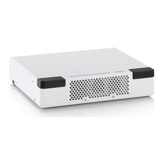
3.2 Instrument tour 3.2.1 Front panel view The front panel of the R&S TSMA6 does not provide any connectors or control ele- ments for operation. The black caps on the left and right contain the WLAN antennas. User Manual 4900.8057.02 ─ 11... -
Page 31: Rear Panel View
Getting started R&S TSMA6 Instrument tour Figure 3-6: R&S TSMA6 - Front Panel 3.2.2 Rear panel view The following figure provides an overview of the control elements and the connectors on the rear panel of the instrument. Figure 3-7: R&S TSMA6 - Rear Panel "USB 2.0 (2x, Type A)"... - Page 32 See (4) in Figure 3-7. Connecting external DC power supply. Ensure that the voltage and current indicated on the R&S TSMA6 match the available power source. Input voltage range: 11 V to 18 V Input current: max. 8.5 A Status LEDs The four status LEDs, [Scanner State], [Scanner Pwr], [Mode], and [Meas] indicated different states of the R&S TSMA6.
- Page 33 The SCAN port provides a high-speed 1 Gbit Ethernet interface with an RJ 45 connec- tor. It is used to connect the R&S TSMA6 to a separate R&S TSME6 as a second scanner. It can be used for MIMO scenarios and for increasing bandwidth and mea- surement rate.
-
Page 34: Built-In Gps Receiver
● Serving as a WLAN access point Per default, the R&S TSMA6 WLAN access point is switched on. The login credentials are found on the bottom label of the device. The WLAN / Bluetooth can be switched off (flight mode) via rear panel switch. -
Page 35: Status Leds
® Getting started R&S TSMA6 Instrument tour Configure the WLAN and Bluetooth settings via web-GUI. ● Chapter A.2.2.1, "Bluetooth", on page 160 ● Chapter A.2.2.2, "WLAN", on page 161 ● Chapter A.2.2.3, "WLAN AP", on page 163 3.2.5 Status LEDs The four LEDs on the rear panel display the following states. - Page 36 ® Getting started R&S TSMA6 Instrument tour Device Scanner [Mode] LED [Meas] LED [Pwr] LED [State]LED Comment red (BLINKING, 2 Hz) Scanner Error Temperature Warn- red (CONT.) Scanner Error Temperature Error red (BLINKING rapidly) SW error User Manual 4900.8057.02 ─ 11...
-
Page 37: Option Concept
The scanner options are available with registered licenses. 4.1.1 Technology options Technology options allow the R&S TSMA6 to scan the input based on a specific tech- nology, for example, LTE. All technology options can be installed on the same instru- ment;... -
Page 38: Band Options
These configurations limit the number of bands that can be mea- sured in parallel. You can reconfigure the bands for each measurement as desired. Upgrade options are available to increase the bandwidth of the R&S TSMA6 from a limited number of bands to full bandwidth. -
Page 39: Software Options
4.2 Software options 4.2.1 R&S NESTOR options The R&S NESTOR options are preinstalled on the R&S TSMA6, if the R&S NESTOR application is ordered within the TSMA6 KMAT. A later installation of additional R&S NESTOR options can be done via the R&S TSMA6 web GUI (see "Install NESTOR Options"... -
Page 40: General Workflows
Connect the R&S TSMA6 LAN socket with an RJ45 cable to the LAN. By default the R&S TSMA6 is configured to use DHCP and no static IP address is set. The R&S TSMA6 shows the IP address in the local web-GUI. -
Page 41: R&S Smartone Based Workflow
® General workflows R&S TSMA6 R&S SmartONE based workflow 5.2 R&S SmartONE based workflow * For details about the prerequisites, see "Prerequisites" on page 40. User Manual 4900.8057.02 ─ 11... - Page 42 ® General workflows R&S TSMA6 R&S SmartONE based workflow User Manual 4900.8057.02 ─ 11...
-
Page 43: Configuring The R&S Tsma6
The Microsoft EDGE browser replaces the former used Internet Explorer for the TSMAx web-GUI and is used as default browser. The R&S TSMA6 web GUI gives the user the full access to control and measure with the R&S TSMA6. Following tasks can be done: ●... -
Page 44: Using Wlan From A Remote Pc Or Smartphone
Chapter A.2.2.3, "WLAN AP", on page 163). 3. Open the browser in the remote device and enter the IP address of the TSMA6 web GUI. http://192.168.137.1/ The TSMA6 web-GUI is displayed on the browser. 6.1.2 Using a remote desktop connection To establish a remote desktop connection with a Windows PC (Win10 is recommen- ded), the following steps have to be performed. - Page 45 TSMA6 Accessing the R&S TSMA6 If you connect the R&S TSMA6 LAN interface with a PC via LAN cable, the IP addresses are negotiated automatically by default. The IP address of the R&S TSMA6 can be read from the local web GUI (see Chapter 6.1.1,...
-
Page 46: Changing Ip Addresses
Configuring the R&S TSMA6 R&S TSMA6 Changing WLAN settings 8. The remote desktop connection is established. The R&S TSMA6 can be controlled from the remote PC. 6.2 Changing IP addresses To change the IP addresses, refer to the following. ● Chapter A.2.2.4, "LAN",... -
Page 47: Selecting Measurement Mode
TSMA6 Selecting measurement mode 6.4 Selecting measurement mode Select the measurement mode with the following steps. 1. Start the R&S TSMA6 web GUI (see Chapter 6.1.1, "Using the R&S TSMA6 web GUI", on page 43). 2. The measurement modes can be configured via the radio button from the web GUI under "Configuration"... -
Page 48: Measurement Modes
6.4.1 Measurement modes 6.4.1.1 PC mode The "PC Mode" is the standard mode for installation of software and for the interactive operation of the R&S TSMA6. In this mode, no software application (NESTOR, SmartONE, QualiPoc) is started in the background. 6.4.1.2 Remote ViCom server mode The "rVicom Server"... -
Page 49: Qualipoc Mode
Install a Remote ViCom client application on the handheld device for this purpose. The connection between the Remote ViCom server on the R&S TSMA6 and the client application (Remote ViCom client) on the handheld device can be realized via Blue- ®... - Page 50 Configuring the R&S TSMA6 R&S TSMA6 Selecting measurement mode 1. Turn on the R&S TSMA6 scanner. 2. In the web-GUI, set the "Mode of Operation" to "QualiPoc" (1) and press "Submit" (2). ® 3. On the handheld device, start the QualiPoc application.
- Page 51 TSMA6 Selecting measurement mode Figure 6-2: Scan for NCM 7. Touch "[Disconnected]", touch the TSMA6 scanner in the list, for example, "TSMA6-900012", and then touch "OK" to accept the pairing request. Figure 6-3: Pair NCM Figure 6-4: Bluetooth pairing request 8.
-
Page 52: Nestor And Nestor Probe Mode
● NESTOR probe mode The R&S TSMA6 hosts only the NESTOR measurement engine. The NESTOR UI engine is hosted on a remote PC connected via LAN/WLAN with the R&S TSMA6. This master PC is required to control the measurement. Prerequisites ●... - Page 53 3. Select a scenario ("Monitoring" or "Cellular Network Analysis"). 4. Press "Submit". The R&S TSMA6 is switched into "NESTOR" mode. In the status bar, the entry is "Changing mode of operation in progress...". The selected mode is active when the status bar displays "No error". The scanner "State"...
-
Page 54: Smartone Mode
Chapter 8.6.3, "R&S SmartONE setup (SmartBenchmarker, ROMES, QualiPoc)", on page 109). To use the R&S TSMA6 with R&S SmartONE, the following steps must be performed. 1. In the web GUI, set the "Mode of Operation" to one of the following SmartONE modes and press "Submit". -
Page 55: Importing Workspace Files (Nestor, Smartone Expert)
For more details about the R&S SmartONE configuration and usage, refer to the user documentation for R&S SmartONE. 6.5 Importing workspace files (NESTOR, SmartONE Expert) Import NESTOR workspace file 1. Start the R&S TSMA6 web GUI from the host PC (see Chapter 6.1.1, "Using the R&S TSMA6 web GUI", on page 43). -
Page 56: Pairing Bluetooth ® Devices
ROMES mode. ® 6.6 Pairing Bluetooth devices To pair the R&S TSMA6 with a remote device, the following steps must be performed. ® For Bluetooth preparation, the device must be in the "PC Mode". Check it via the web GUI ("Home"... -
Page 57: Changing Keyboard Language
7. On the remote device, confirm the Bluetooth pairing code. 6.7 Changing keyboard language ® By default, the R&S TSMA6 is delivered with the English version of Windows 10 and it supports the English keyboard. To use the german keyboard (or any other one), pro- ceed as follows. - Page 58 ® Configuring the R&S TSMA6 R&S TSMA6 Changing keyboard language 2. Select "Add a language" under " Clock, Language, and Region". 3. The "Language" settings window opens and by default only English is listed there. To add a new language, click the "Add a language" tile.
-
Page 59: Enabling Virtual Memory
6. After successfully adding the language, it should be listed as selectable language. 7. Change the keyboard language via windows taskbar. 6.8 Enabling virtual memory To enable virtual memory on the R&S TSMA6, perform the following steps: 1. Open "Settings". User Manual 4900.8057.02 ─ 11... - Page 60 ® Configuring the R&S TSMA6 R&S TSMA6 Enabling virtual memory 2. Select "System and Security". 3. Select "Advanced System Settings". 4. Select the tab "Advanced". User Manual 4900.8057.02 ─ 11...
- Page 61 ® Configuring the R&S TSMA6 R&S TSMA6 Enabling virtual memory 5. Select "Settings..." in the section "Performance". 6. Select the tab "Advanced". 7. Select "Change..." in the section "Virtual memory". 8. Enable "Automatically manage paging file size for all devices".
- Page 62 ® Configuring the R&S TSMA6 R&S TSMA6 Enabling virtual memory 9. Click "OK" to close the dialog. 10. Reboot the device. User Manual 4900.8057.02 ─ 11...
-
Page 63: Measurement Setup
TSMA6 Vibration-proofed stacking 7 Measurement Setup 7.1 Vibration-proofed stacking 7.1.1 Cascading R&S TSMA6/6B and R&S TSME6 To connect R&S TSMA6/6B and R&S TSME6 1. Screw the connecting elements (order no. 4900.0804.00) on the top of the R&S TSMA6/6B. Torque: 0.66 Nm ± 0.05 Nm ●... -
Page 64: Connecting R&S Tsma6/6B With R&S Tsma6-Bp
7.1.2 Connecting R&S TSMA6/6B with R&S TSMA6-BP Before initial operation, the batteries must be fully charged without an R&S TSMA6 connected. To connect the R&S TSMA6/6B with the R&S TSMA6, the following steps must be per- formed. To connect a battery pack 1. - Page 65 Torque: 0.66 Nm ± 0.05 Nm ● Figure 7-3: Collar screws 1 = Collar screws 3. Align the collar screws with the snap-in holes on the bottom of an R&S TSMA6/6B and press the device down. User Manual 4900.8057.02 ─ 11...
- Page 66 3 = R&S TSMA6/6B 4 = Snap in holes on the bottom pane of R&S TSMA6/6B 4. Move the R&S TSMA6/6B to the rear side (2) until you hear a click when the collar screws are locked in. User Manual 4900.8057.02 ─ 11...
-
Page 67: Connecting R&S Tsma6/6B-Bp With R&S Tsme6 And R&Stsmexxdc/Tsms53Dc
R&S TSME6 user manual and the R&S TSMExxDC/ R&S TSMS53DC manual. 1. Screw the collar screws (1) on the top of the R&S TSMA6/6B-BP with a Torx 8 screw driver. Torque: 0.66 Nm ± 0.05 Nm ●... - Page 68 R&S TSME-ZYC) 2. Align the collar screws with the snap-in holes on the bottom of an R&S TSME6/ TSMExxDC/TSMS53DC and press the device down. Figure 7-6: Example: Aligning R&S TSMA6/6B-BP and R&S TSME6 1 = R&S TSMA6/6B-BP 2 = Collar screws 3 = R&S TSME6/TSMExxDC/TSMS53DC...
-
Page 69: Connecting The R&S Tsma6 With Multiple Devices
The connection of up to 4 R&S TSME6/TMSExxDC devices is possible. ● For up to 2 devices, 1 x R&S TSMA6-BP2T dual power cable or 2 x R&S TSMA6 BPPT single power cables are required. ●... - Page 70 Setup with TSMA6B-BP + TSME6 + TSMExxDC Connect up to two R&S TSME6/TSMExxDC. Use one of the following solutions. ● Connect the devices with 2 x R&S TSMA6-BPPT single power cables to AUX1 and AUX2 port of the R&S TSMA6 (see Figure 7-9).
- Page 71 R&S TSME6/TSMExxDC accessory or can be ordered as spare parts (R&S no. 4900.0804.00). 1. Screw the collar screws on the top of the R&S TSMA6 with a Torx 8 screw driver. Torque: 0.66 Nm ± 0.05 Nm ●...
- Page 72 4 = Snap-in holes on the bottom pane of R&S TSME6 and R&S TSMExxDC 5 = R&S TSMExxDC 3. Connect DC power cable R&S TSMA6-BPP1 resp. R&S TSMA6-BP2T from AUX1 / AUX2 to the DC IN socket of the devices (see Figure 7-12).
- Page 73 67. 2. For the devices 3 and 4, screw the additional collar screws on top of the already mounted devices. Figure 7-13: Aligning R&S TSMA6, 2x R&S TSME6 and R&S TSMExxDC 1 = Collar screws User Manual 4900.8057.02 ─ 11...
- Page 74 2 = Collar screws 3 = 2nd R&S TSME6/TSMExxDC = Snap-in holes on the bottom pane of R&S TSME6/TSMExxDC 4. Connect DC power cable R&S TSMA6-BPP1 resp. R&S TSMA6-BP2T from AUX1 / AUX2 to the DC IN socket of the devices (seeFigure 7-12...
-
Page 75: Disconnecting The R&S Tsma6 From R&S Tsmx Devices
3. Disconnect all other cables of the devices. 4. Remove the R&S TSMx devices. 5. Only for R&S TSMA6/6B: Lift the release button (1) on both sides of the R&S TSMA6/6B and slide it in direction (2) until the device is released. -
Page 76: Use Cases
® Measurement Setup R&S TSMA6 Use cases Figure 7-16: Disconnect R&S TSMA6/6B 7.2 Use cases In the following, you find several uses cases with different combinations of TSMAx devices. User Manual 4900.8057.02 ─ 11... -
Page 77: R&S Tsma6 With R&S Tsme6 And R&S Tsma6-Bp
4 = RF: R&S TSMA6 RF In < 6 GHz 5 = RF: R&S TSME6 For the LAN connection between R&S TSMA6 and R&S TSME6, you need LAN cable of type CAT6. Change the SCAN port of the R&S TSMA6 via the web-GUI to DHCP (see "TCP/IP... -
Page 78: R&S Tsma6 With R&S Tsmexxdc And R&S Tsma6-Bp
Additional devices like R&S TSME6 and R&S TSMExxDC can also be mounted to the side. Figure 7-18: Example: R&S TSMA6 with R&S TSME6 mounted to the side 7.2.2 R&S TSMA6 with R&S TSMExxDC and R&S TSMA6-BP Figure 7-19: R&S TSMA6 + R&S TSMExxDC 1 = Synchronization: R&S TSMA6 - R&S TSMExxDC... - Page 79 GHz). The R&S TSME44DC offers only one RF connector with a frequency range from 24 GHz to 44 GHz. If the R&S TSMA6 is connected with an R&S TSMA6-BP, DC power must be connec- ted to the R&S TSMA6-BP (1).
-
Page 80: R&S Tsma6 With R&S Tsmexxdc, R&S Tsme6 And R&S Tsma6-Bp
= RF: R&S TSMExxDC RF In 27 GHz to 30 GHz = RF: R&S TSMExxDC IF1 - R&S TSME6 RF In For the LAN connection between R&S TSMA6 and R&S TSME6, you need LAN cable of type CAT6. For the synchronization between R&S TSMA6 and R&S TSMExxDC / R&S TSME6, you need the synchronization cable R&S TSME6-ZC4, which is required for 3 and... - Page 81 R&S TSMA6 Use cases If the R&S TSMA6 is connected with a R&S TSMA6-BP, DC power must be connected to the R&S TSMA6-BP (1). Do not connect the DC power to the R&S TSMA6 (2). Figure 7-22: DC IN connectors 1 = DC IN connector R&S TSMA6-BP...
-
Page 82: Installing Firmware And Software Updates
For R&S NESTOR, R&S SmartONE and R&S ViCom, contact the appropriate sales channel. 8.2 Prerequisites To execute the setup on the R&S TSMA6, the mode of operation has to be "PC Mode". 1. Open the R&S TSMA6 web GUI (see Chapter 8.3.4, "Calling R&S TSMA6 web GUI",... - Page 83 ® Installing firmware and software updates R&S TSMA6 Prerequisites 3. If a different mode is activated, navigate to "Configuration" > "System" > "Mode", select the "PC Mode" and press the "Submit" button. User Manual 4900.8057.02 ─ 11...
-
Page 84: Updating Firmware/Software/Tools - General Instructions
PC. 1. Connect a mouse and a keyboard to USB ports and a monitor to the HDMI port. The setup file must be available on the R&S TSMA6 or on a USB stick. User Manual 4900.8057.02 ─ 11... - Page 85 R&S TSMA6 Updating firmware/software/tools - general instructions 2. Switch on the R&S TSMA6 via the power button. 3. Copy the setup file for firmware/software/EDGE/TsmeTools (.zip or .exe) into a temporary directory on the R&S TSMA6. 4. Check that R&S TSMA6 is in "PC Mode", see Chapter 8.2,...
- Page 86 ® Installing firmware and software updates R&S TSMA6 Updating firmware/software/tools - general instructions 8. Select "Next>". 9. The package dialog lists all the available packages in the setup. In general, you can skip this dialog without any changes. Select "Automatic Reboot".
- Page 87 ® Installing firmware and software updates R&S TSMA6 Updating firmware/software/tools - general instructions Note: Do not switch off or unplug from power while running firmware/software update. 11. The device reboots automatically after the installation is complete. If the automatic reboot is not started, reboot manually.
-
Page 88: Remote Installation Of The Setup File
Using LAN connection ● Connect the LAN port of the R&S TSMA6 with the host PC LAN port. The LAN port is marked with the LAN symbol. The default IP setting of this port is "DHCP client". For details on how to configure the remote PC, contact your network administrator. - Page 89 ® Installing firmware and software updates R&S TSMA6 Updating firmware/software/tools - general instructions 4. Select "Remote Installation" and "Next>". 5. In the License Agreement window, check "I accept the license agreement". 6. Select "Next>". User Manual 4900.8057.02 ─ 11...
- Page 90 All packages, which you need to install, are already pre-selected. 8. Select "Next>". 9. After a while, all R&S TSMA6 devices in the network are listed in the "Device List" dialog. Devices are only listed, if the device is in "PC Mode" (see Chapter 8.2, "Prerequi-...
- Page 91 11. The state of the installation process is displayed in the "Status" column. The proc- ess is finished when the status indicates "Ready, see report for details!". Note: If you are connected via WLAN, a reconnect to the R&S TSMA6 WLAN access point may be necessary as the R&S TSMA6 reboots after the firmware/soft- ware update.
-
Page 92: Installation Using A Usb Stick
8.3.3 Installation using a USB stick The setup will be initiated via the web GUI of the R&S TSMA6. In this case, the setup file must be available in the root directory of a USB stick, which is connected to the R&S TSMA6. - Page 93 ® Installing firmware and software updates R&S TSMA6 Updating firmware/software/tools - general instructions 9. A confirmation dialog appears. Confirm with "OK" to start the update. 10. The firmware/software installation starts. The status text in the web GUI displays "Installation in progress…".
- Page 94 TSMA6 reboots. After reboot the firmware is running a selftest (Mode LED is blinking green). Note: If you are connected via WLAN, a reconnect to the R&S TSMA6 WLAN access point may be necessary. 12. Open the web GUI. After a while, the status text in the web GUI changes to No error.
-
Page 95: Calling R&S Tsma6 Web Gui
47. 8.3.4 Calling R&S TSMA6 web GUI The R&S TSMA6 web GUI has to be loaded prior to executing firmware / software setup. ● Remote from a WLAN connected device Start the web browser and enter the following URL: http://192.168.137.1... -
Page 96: Subsequent Steps After Firmware Update
Installing firmware and software updates R&S TSMA6 R&S TSME Tools update TSMAx-xxxxxx = R&S TSMA6 host name This information can be found on a label at the bottom. ● Local Open the web browser (Microsoft EDGE or Internet Explorer). The web GUI starts automatically. -
Page 97: Preparation
® Installing firmware and software updates R&S TSMA6 R&S TSME Tools update 8.4.1 Preparation 1. Download the R&S TSME Tools setup file TSMAx-TsmeTools-v<x.y.z.z1>.exe from https://www.rohde-schwarz.com/ software/tsma6/. 2. Choose the way of installation (local, remote, USB stick) and follow the instructions on how to update the R&S TSME Tools (see... -
Page 98: R&S Tsme Tools Remote Installation
® Installing firmware and software updates R&S TSMA6 R&S TSME Tools update 8.4.3 R&S TSME Tools remote installation Follow the general instructions in Chapter 8.3.2, "Remote installation of the setup file", on page 88, step 1 step The "R&S Software Distributor" comes up. Select "Remote Installation" and "Next >". -
Page 99: Microsoft Edge Browser Update
For the Microsoft EDGE browser installation on the R&S TSMA6/TSMA6B use the dedicated TSMAx EDGE setup. TSMAx-EDGE-Setup-<version>.zip. Example: TSMAx-EDGE-Setup-V4.1.0.5.zip (current version). This setup is only for R&S TSMA6 and TSMA6B. (Not suitable for R&S TSMA.) User Manual 4900.8057.02 ─ 11... -
Page 100: Preparation
® Installing firmware and software updates R&S TSMA6 Microsoft EDGE browser update 8.5.1 Preparation 1. Download the Microsoft EDGE browser setup file TSMAx-EDGE-Setup-<version>.zip from https://www.rohde-schwarz.com/ software/tsma6/. 2. Choose the way of installation and follow the instructions how to update the browser. -
Page 101: Microsoft Edge Browser Remote Installation
® Installing firmware and software updates R&S TSMA6 Microsoft EDGE browser update 8.5.3 Microsoft EDGE browser remote installation Follow the general instructions in Chapter 8.3.2, "Remote installation of the setup file", on page 88, step 1 step The "R&S Software Distributor" comes up. Select "Remote Installation" and "Next >". -
Page 102: Software Update - Details
8.6 Software update - details Make sure, that the latest firmware is installed on the device before you start with the installation of software packages. For software installations (NESTOR, SmartONE, ViCom) installation, only use the TSMA6-specific setup files (TSMAx-<AppName>-|<version>-setup.exe). User Manual 4900.8057.02 ─ 11... -
Page 103: Remote Vicom Server Software
The update of the Remote ViCom package installation could be neglected for other modes of operation (NESTOR, ROMES, QualiPoc). The installed version of the Remote ViCom server on the R&S TSMA6 needs to match with the applied version of rViCom client API on the remote Android device. -
Page 104: Vicom Server Remote Installation
® Installing firmware and software updates R&S TSMA6 Software update - details All subsequent steps are similar to local firmware installation, see Chapter 8.3.1, "Local execution of the setup file", on page 84, step 7 and following. Do not switch off or unplug from power while running firmware/software update. -
Page 105: Vicom Server Installation Using A Usb Stick
® Installing firmware and software updates R&S TSMA6 Software update - details All subsequent steps are similar to remote firmware installation, see Chapter 8.3.2, "Remote installation of the setup file", on page 88, step 5 and following. 8.6.1.4 ViCom server installation using a USB stick Follow the general instructions in Chapter 8.3.3, "Installation using a USB... -
Page 106: R&S Nestor Software
92, step 9 and following. 8.6.2 R&S NESTOR software Only execute the dedicated NESTOR setup for R&S TSMA6. The setup file is named TSMAx_NESTOR_Setup-<Version>.exe. 8.6.2.1 Preparation This software package is pre-installed at delivery when the R&S TSMA6 is ordered with NESTOR TSMA6 option (R&S No. -
Page 107: Nestor Local Installation
® Installing firmware and software updates R&S TSMA6 Software update - details 8.6.2.2 NESTOR local installation Follow the general instructions in Chapter 8.3.1, "Local execution of the setup file", on page 84, step 1 step The "R&S Software Distributor" comes up. Select "Local Installation" and "Next". -
Page 108: Nestor Installation Using A Usb Stick
® Installing firmware and software updates R&S TSMA6 Software update - details All subsequent steps are similar to remote firmware installation, see Chapter 8.3.2, "Remote installation of the setup file", on page 88, step 5 and following. 8.6.2.4 NESTOR installation using a USB stick Follow the general instructions in Chapter 8.3.3, "Installation using a USB... -
Page 109: R&S Smartone Setup (Smartbenchmarker, Romes, Qualipoc)
® Installing firmware and software updates R&S TSMA6 Software update - details The following steps are similar to the installation using a USB stick, see Chapter 8.3.3, "Installation using a USB stick", on page 92, step 9 and following. 8.6.3 R&S SmartONE setup (SmartBenchmarker, ROMES, QualiPoc) It is recommended to install and use the Microsoft Edge browser with R&S SmartONE. -
Page 110: Preparation
® Installing firmware and software updates R&S TSMA6 Software update - details 8.6.3.1 Preparation 1. Download the SmartONE setup file TSMAx-SmartONE_x.y.z.exe from the Rohde & Schwarz FTP server respectively SmartONE CD-ROM. 2. Choose the way of installation and follow the instructions how to prepare. -
Page 111: Initial Software Start / Measurement Mode Selection
® Installing firmware and software updates R&S TSMA6 Software update - details All subsequent steps are similar to remote firmware installation, see Chapter 8.3.2, "Remote installation of the setup file", on page 88, step 5 and following. 8.6.3.4 Initial software start / measurement mode selection After the successful installation of R&S SmartONE, the device always is in "QualiPoc"... - Page 112 ® Installing firmware and software updates R&S TSMA6 Software update - details 4. Select "Submit". After starting R&S ROMES, configure the following settings. 1. In the "Romes Technology Selector", select the technologies to be supported by your ROMES installation. User Manual 4900.8057.02 ─ 11...
- Page 113 ® Installing firmware and software updates R&S TSMA6 Software update - details 2. Select "OK". 3. In the "ROMESTecSelectorGUI" window, select "OK". The current installation is adapted according to your selection and the ROMES start process continues. 4. In the "User" window, check that the "User Level" is "Normal".
-
Page 114: Capture And Apply R&S Tsma6 Images
3. As "Mode of Operation", select "SmartONE Standard". For further details about using R&S SmartBenchmarker, refer to R&S SmartBench- marker - Manual. 8.7 Capture and apply R&S TSMA6 images Use the R&S TSMA6 image stick to capture and apply Windows images. User Manual 4900.8057.02 ─ 11... -
Page 115: Create An R&S Tsma6 Image Stick
TSMA6............... 118 8.7.1 Create an R&S TSMA6 image stick You need administrator rights on the PC, where you create the image stick. To create an R&S TSMA6 image stick, proceed as follows. Prerequisites: ● A bootable USB stick (USB 3.1 Gen1) with a capacity of at least 64 GB. Make sure that the data on the USB stick is no longer needed as it will be formatted during process of R&S TSMA6 image stick creation. -
Page 116: Boot From The R&S Tsma6 Image Stick
Capture and apply R&S TSMA6 images ● bootmgr.efi When the creation of the image stick has finished, you can boot the R&S TSMA6 from this stick. 8.7.2 Boot from the R&S TSMA6 image stick To boot from the R&S TSMA6 image stick, proceed as follows. - Page 117 ® Installing firmware and software updates R&S TSMA6 Capture and apply R&S TSMA6 images 3. After the capture process has finished, the message "Operation successfully done." appears. User Manual 4900.8057.02 ─ 11...
-
Page 118: Apply An Image To An R&S Tsma6
8.7.4 Apply an image to an R&S TSMA6 To apply an image to an R&S TSMA6, the following files must be available in the direc- tory Device/Images on the R&S TSMA6 image stick. - Page 119 ® Installing firmware and software updates R&S TSMA6 Capture and apply R&S TSMA6 images 3. After the apply process has finished, the message "Operation successfully done." appears. 4. Press "OK". User Manual 4900.8057.02 ─ 11...
- Page 120 ® Installing firmware and software updates R&S TSMA6 Capture and apply R&S TSMA6 images 5. Remove the R&S TSMA6 image stick. 6. Press "Reboot". The R&S TSMA6 reboots from the deployed image. User Manual 4900.8057.02 ─ 11...
-
Page 121: Installing Software Options (Scanner, Nestor)
"Install XML file." 9.2 Installing R&S NESTOR options A later enhancement of the R&S TSMA6 with options requires a USB license dongle. To install R&S NESTOR options, perform the following steps. 1. Start the web GUI of the R&S TSMA6. -
Page 122: User Backup And Restore
During the backup, do not interrupt the procedure or disconnect the power supply. To create a user backup, click the " Backup" button in the web GUI "(Backup"), see "Backup TSMA6 System" on page 168. A backup of the system partition C:\ is cre- ated. -
Page 123: Restore Factory Backup
Restore factory backup Loss of user settings after restore Executing restore brings the R&S TSMA6 irreversible back to the condition of delivery or any other subsequently stored user backup version. On the C:\ drive, all user settings and installed programs since the last backup will be deleted. - Page 124 Restore factory backup 4. Select "Factory Default Restore". 5. Select "Start Recovery". The R&S TSMA6 recovery starts and the "Mode" LED blinks green. NOTE: Do not interrupt the recovery process. 6. When the recovery has finished, press Exit/Reboot. 7. After the reboot, check if a microcontroller flash is performed (LED blue/green).
-
Page 125: Troubleshooting
Write battery info into firmware log file..............126 ● Verify scanner link / recall device info using TSME Device Manager....127 ● R&S TSMA6 automatically switches off after power on........131 ● Scanner is not found from software (R&S ROMES, R&S NESTOR)....132 ●... -
Page 126: Evaluate Selftest File
® Troubleshooting R&S TSMA6 Write battery info into firmware log file 11.2 Evaluate selftest file ● Path: C:\ProgramData\Rohde-Schwarz\TSMA\Selftestresults ● Filename: Selftestresult.txt Entries in the Selftestresult.txt are created during the boot process of the device and every 5 minutes. To open the Selftestresult.txt, proceed as follows. -
Page 127: Verify Scanner Link / Recall Device Info Using Tsme Device Manager
130). If the connection to an R&S TSMA6 is not established correctly, for example due to a mismatch of the scanner link IP configuration, only limited information is displayed. In this case, no information about installed options is available. - Page 128 R&S TSMA6 Verify scanner link / recall device info using TSME Device Manager Figure 11-1: Tab "Device Info" The table includes the following information: Table 11-1: R&S TSMA6 device information Label Description Device Device Type Type of device (TSME family, TSMA family) Material Number Order number of the R&S TSMA6...
-
Page 129: Device Analysis Output
Verify scanner link / recall device info using TSME Device Manager Label Description Product Change Index Version of the device MAC Address Network address of the R&S TSMA6 FPGA Available FPGA Bit File Ver- Previous firmware version backups stored on the device) sions Current FPGA Bit File Version... -
Page 130: Verify Installed License Keys
Verify scanner link / recall device info using TSME Device Manager In case measurement problems occur with the R&S TSMA6, check the "Device Analy- sis Output" table for any errors that may have been detected. If available, a repair func- tion is provided. -
Page 131: R&S Tsma6 Automatically Switches Off After Power On
Connect DC supply to the R&S TSMA6 battery pack unit and charge the batter- ies inside the bay. Keep the R&S TSMA6 switched off. 4. Connect DC supply to the R&S TSMA6 battery pack unit and check in the web GUI the "Shutdown Settings". -
Page 132: Scanner Is Not Found From Software (R&S Romes, R&S Nestor)
® Troubleshooting R&S TSMA6 Scanner is not found from software (R&S ROMES, R&S NESTOR) 11.7 Scanner is not found from software (R&S ROMES, R&S NESTOR) To check if the scanner unit is working properly, perform the following steps. User Manual 4900.8057.02 ─ 11... - Page 133 If an error is listed, check the error type. ● If no error is listed, continue with step 3 3. Start the web GUI (see Chapter 6.1.1, "Using the R&S TSMA6 web GUI", on page 43). Check "Mode of Operation" and "IP Settings". ●...
- Page 134 Scanner is not found from software (R&S ROMES, R&S NESTOR) ● If the "Mode of Operation" != "PC Mode", switch mode to "PC Mode". Restart the R&S TSMA6 via web GUI and check the LEDs, see step ● If the IP address of the "SCAN Port (int)" = "192.168.0.1", continue with step ●...
-
Page 135: Verify Lan Settings (Internal Scanner Connection)
Verify LAN settings (internal scanner connection) 7. Check in the "Info" tab, if any device is available. ● If the R&S TSMA6 device is found, check the "Device Analysis Output". ● If the R&S TSMA6 device is not found, contact the R&S support. - Page 136 Troubleshooting R&S TSMA6 Verify LAN settings (internal scanner connection) Figure 11-3: TSMA6 scanner connection 2. Double-click the "TSMA6 Scanner Connection Int " entry and verify the following settings. ● IP address: 192.168.0.1 (static IP address) ● "Jumbo Packet": 9014 Bytes...
-
Page 137: No Remote Access Via Lan Port
TSMA6 No remote access via LAN port 11.9 No remote access via LAN port If the R&S TSMA6 could not be accessed for remote control or remote desktop session via the LAN port, check following issues: Optical check 1. Check on the rear panel, if the LAN cable is connected to the remote control LAN... - Page 138 Figure 11-5: Web GUI - LAN Connection Ping command Execute the ping command from the Windows command prompt on the host PC. 1. Use the IP address displayed in the R&S TSMA6 web GUI (see Figure 11-4). 2. Start the ping command.
- Page 139 3. The entry "TSMA6 LAN Connection" must be available. Figure 11-6: TSMA6 LAN Connection 4. If the "TSMA6 LAN Connection" is not listed in the "Network Connections", a recov- ery of the R&S TSMA6 is recommended (see Chapter 10, "User backup and restore",...
-
Page 140: Wlan Access Point Not Detected By External Pc, Mobile Or Tablet
11.10 WLAN access point not detected by external PC, mobile or tablet With the first R&S TSMA6 devices shipped, the WLAN module is configured to use the 2.4 GHz and 5 GHz band. In environments with high traffic on the 2.4 GHz band, the R&S TSMA6 access point sometimes switches into the 5 GHz band after power-up. - Page 141 ® Troubleshooting R&S TSMA6 WLAN access point not detected by external PC, mobile or tablet 4. Verify the IP settings via the web GUI. Navigate to "Home" > "IP Settings". IP address of WLAN AP = 192.168.137.1 5. Verify WLAN adapter settings.
-
Page 142: Web Gui Not Accessible Via Wlan Connection
122) or contact R&S support. 11.11 Web GUI not accessible via WLAN connection If the R&S TSMA6 web GUI is not accessible, perform the following steps to solve the problem. 1. Check if the WLAN AP is activated. -
Page 143: Web Gui Locally Not Accessible
11.12 Web GUI locally not accessible Open the web GUI locally. Start the Internet Explorer and enter the following URL to open the R&S TSMA6 web GUI. http://localhost 1. Check the URL in the browser dialog. Following URL must be displayed: http://localhost/TSMA/Html/overview.php... - Page 144 If the services could not be started, reinstall the firmware (see Chapter 8.3, "Updat- ing firmware/software/tools - general instructions", on page 84). 4. Try again to start the web GUI locally on the R&S TSMA6 via Internet Explorer. User Manual 4900.8057.02 ─ 11...
-
Page 145: Slow/Instable Wlan Connection
The visibility of an Android device with firmware version ≥5.0 cannot be changed. The mobile (tablet) is only visible to other devices when the "Bluetooth Properties" window is open. If you are controlling the R&S TSMA6 web GUI with the mobile and also want to couple ® the devices via Bluetooth , then you have to perform following steps. - Page 146 R&S TSMA6 3. After choosing the R&S TSMA6, you receive a "Bluetooth pairing request". Click "OK". 4. Open the R&S TSMA6 web GUI and navigate to "Configuration" > "Connectivity" > "Bluetooth". 5. Execute "Refresh Device List".
-
Page 147: No Rf / Gps Data
® Troubleshooting R&S TSMA6 No RF / GPS data If you need to transport or ship the product, see Chapter 12, "Transporting", on page 149. 11.15 No RF / GPS data 1. Check if the RF antenna is connected to the RF port. -
Page 148: Contacting Customer Support
® Troubleshooting R&S TSMA6 Contacting customer support ● If no errors are reported or if the repair actions via the "Device Analysis Output" window fail, contact the R&S support. 11.16 Contacting customer support Technical support – where and when you need it For quick, expert help with any Rohde &... -
Page 149: Transporting
® Transporting R&S TSMA6 12 Transporting Packing Use the original packaging material. It consists of antistatic wrap for electrostatic pro- tection and packing material designed for the product. If you do not have the original packaging, use similar materials that provide the same level of protection. -
Page 150: Maintenance, Storage And Disposal
® Maintenance, storage and disposal R&S TSMA6 Disposal 13 Maintenance, storage and disposal The product does not require regular maintenance. It only requires occasional clean- ing. It is however advisable to check the nominal data from time to time. 13.1 Cleaning Do not use any liquids for cleaning. - Page 151 ® Maintenance, storage and disposal R&S TSMA6 Disposal Figure 13-2: Disposal information in line with EU battery directive Dispose of batteries as specified by the local waste disposal agency. Alternatively, you can contact the Rohde & Schwarz local service representative.
-
Page 152: Annex
The "System" window consists of the following tabs. ● Overview....................... 152 ● settings......................154 ● info......................... 155 A.1.1 Overview The "Overview" tab displays the following basic settings of the R&S TSMA6. Device Info........................153 └ Type......................153 └ Material No....................153 └... - Page 153 Serial No. ← Device Info Serial number of the device Computer Name ← Device Info Computer name of the R&S TSMA6 (read-only). The name consists of a fixed part (TSMA6) and a variable part (serial number). Example: R&S TSMA6-<Serial Number>...
-
Page 154: Ip Settings
® Web GUI reference R&S TSMA6 Home ● number is the version of the basic image ● number is the version of the device installation Firmware ← FW/SW Version Firmware version NESTOR ← FW/SW Version Installed R&S NESTOR version (optional) ROMES ←... -
Page 155: Hw Info
® Web GUI reference R&S TSMA6 Home LAN..........................155 SCAN (Int.)........................155 SCAN........................155 LAN EXT2 / EXT3 / EXT 5 / EXT6................155 WLAN AP (Overview)....................155 IP address of the remote LAN port SCAN (Int.) IP address of the internal scanner link LAN SCAN IP address of the "SCAN"... - Page 156 Serial number and product change index of the RF board. Mainboard ← Module Info Serial number and product change index of the main board. Batterypack ← Module Info Serial number and product change index of the battery pack module (TSMA6-BP). User Manual 4900.8057.02 ─ 11...
-
Page 157: Configuration
® Web GUI reference R&S TSMA6 Configuration CPU Info CPU system information Down Converter Info System information of the connected downconverter device. Available Config. ← Down Converter Info All stored firmware versions on the downconverter device. Used Config. ← Down Converter Info Currently used firmware version on the downconverter device. -
Page 158: Mode
DC power is applied again. Delayed System Start Note: To support this mode, connect a R&S TSMA6 battery pack. The delay time is configured at the R&S TSMA6x. After pressing "Activate" and "Shut- down", the device enters sleep mode and starts after the configured delay. The sleep mode is indicated with a green blinking "Mode"... -
Page 159: Speaker
Press "Submit Timoe ut" to enable this feature. The R&S TSMA6x with a connected battery pack unit will automatically power down after the configured time delay when the DC power is removed from the R&S TSMA6 battery pack. A.2.1.3 Speaker The "Speaker"... -
Page 160: Watchdog
Web GUI reference R&S TSMA6 Configuration Change Instrument Password Changes and confirms a new password for the R&S TSMA6. Current Password ← Change Instrument Password Enter the current valid password. New Password ← Change Instrument Password Enter a new password. -
Page 161: Wlan
® Web GUI reference R&S TSMA6 Configuration Visibility ← Bluetooth Connection The Bluetooth adapter can be set to visible or hidden for external devices. Bluetooth Device(s) ← Bluetooth Connection Press "Refresh" to update visible Bluetooth devices. For pairing a device, select it in the file box and press "Connect". - Page 162 ® Web GUI reference R&S TSMA6 Configuration TCP/IP Mode (WLAN Client) ← WLAN Adapter The IP address configuration in a client connection can be switched between "DHCP" (receive IP address from host) and static IP ("Static"). Enter the static IP configuration in the dialog below.
-
Page 163: Wlan Ap
Enter a new network key for the specified SSID Confirm Network Key ← WLAN Access Point To confirm the new network key, enter it again. A.2.2.4 Configure the "LAN" port IP of the R&S TSMA6. This is the port marked with the LAN symbol. Connection......................164 └... -
Page 164: Lan Scan
● DNS Server It is possible to specify a primary and a secondary DNS server. A.2.2.5 LAN SCAN Configure the "LAN SCAN" port of the R&S TSMA6. This is the port marked with "SCAN". LAN Connection (LAN SCAN)..................164 └ State (LAN SCAN).................. -
Page 165: Lan Ext2 / Ext3 / Ext5 / Ext6
It is possible to specify a primary and a secondary DNS server. A.3 File transfer The "File Transfer" window offers the following functions: ● Uploads and downloads of files to/from the R&S TSMA6. ● Download of the Vicom sample application to an Android device. File Transfer........................ -
Page 166: Options
With "Restore Default", the default path D:\Upload is selected. Download ← File Transfer Specifies the measurement data file to be transferred from the R&S TSMA6 (D:\Download) to a connected device. With "Apply Path", you can specify a user specific path for uploading files. -
Page 167: Install
Start and expiration date of the license key Option Index Index number of the license key A.4.2 Install The "Install" tab is used to install various license key files on the R&S TSMA6. Install NESTOR Options....................167 Install Scanner Options....................167 Install NESTOR Options Enter the NESTOR license key and press "Install"... -
Page 168: Backup
● You can store only one user backup. An existing user backup is overwritten when running backup again. A.7 Restart The "Restart" window allows to restart the complete R&S TSMA6 and the scanner unit separately. System restart......................168 PowerCycle......................... 169 System restart To restart the R&S TSMA6, click "Restart". -
Page 169: Help
To restart the scanner unit of the R&S TSMA6, click "PowerCycle". The following message appears. Click "OK" to reboot the scanner unit of the R&S TSMA6. A.8 Help The "Help" window displays the online help system of the R&S TSMA6. User Manual 4900.8057.02 ─ 11... -
Page 170: B Introduction To Remote Vicom Sample App
Remote rViCom Server on the R&S TSMA6 (default) ● An installed Sample App on the Android device The version of the rViCom server on the R&S TSMA6 must match the version of the Sample App on the Android device. B.2.2 Preparation Before starting a scan or test, it is necessary to make sure that a connection can be established. -
Page 171: Usage
Start the Sample App on the Android device. B.3.1.1 Connection type selection To connect to the R&S TSMA6 Remote rViCom Server, it is either possible to use a WLAN connection or a Bluetooth connection. The selection of the connection type depends on the measurement task (see Chap- ter B.3.1, "Connection... - Page 172 ® Introduction to Remote ViCom Sample App R&S TSMA6 Usage Figure B-2: Active Server Discovery 3. If a server is found, the server will be connected and the name of the server is dis- played. Figure B-3: Successful Server Discovery 4.
-
Page 173: Gsm Rssi Scan
® Introduction to Remote ViCom Sample App R&S TSMA6 Usage The following scan types are available: ● GSM RSSI Scan Provides a GSM scan by selecting a band and radio channels ● WCDMA Top-N Pilot Scan Provides an UMTS scan by selecting a frequency band and the UARFCN ●... -
Page 174: Gsm Scan Results
® Introduction to Remote ViCom Sample App R&S TSMA6 Usage 3. Click "Start scan" to start the scan. B.3.2.2 GSM scan results The GSM scan result graph displays one column for each channel selected. The height of a column represents the RSSI value (in dBm). -
Page 175: Wcdma Top-N Pilot Scan
® Introduction to Remote ViCom Sample App R&S TSMA6 Usage B.3.3 WCDMA Top-N pilot scan B.3.3.1 WCDMA Top-N pilot preferences To start a WCDMA scan, the following steps must be performed. 1. Choose a frequency band. The minimum UARFCN of this band is set automatically. -
Page 176: Lte Top Signal Scan
® Introduction to Remote ViCom Sample App R&S TSMA6 Usage Figure B-8: WCDMA Scan Result View Below the graph the measurement preferences and the status are displayed. Parameters Displays the configured preferences for the WCDMA scan. Status Displays the measurement duration and the measurement rate. The status button dis- plays the following colored states. -
Page 177: Lte Top Signal Scan Results
® Introduction to Remote ViCom Sample App R&S TSMA6 Usage Figure B-9: Setting the LTE Preferences 2. If necessary, change the EARFCN according to your needs. Note: Due to processing issues, it is not possible to select more than one EARFCN. -
Page 178: Throughput Test Case
® Introduction to Remote ViCom Sample App R&S TSMA6 Usage Status Displays the measurement duration and the measurement rate. The status button dis- plays the following colored states. ● Green The measurement is running and measurement data are received. ●... -
Page 179: Rf Power Scan
® Introduction to Remote ViCom Sample App R&S TSMA6 Usage ● y-axis The y-axis displays the corresponding throughput value (kB/s) The blue line shows the measured values. The orange line represents the visualized average of all values. Figure B-12: Throughput Result View Below the graph the following throughput results are displayed. -
Page 180: Rf Power Scan Results
® Introduction to Remote ViCom Sample App R&S TSMA6 Usage Figure B-13: RF Power Scan References 2. Click "Start Test" to start the scan. B.3.6.2 RF power scan results The result of the RF power scan is a spectrum of the frequency range set before with the following axes: ●... - Page 181 ® Introduction to Remote ViCom Sample App R&S TSMA6 Usage Status Displays the measurement duration and the measurement rate. The status button dis- plays the following colored states. ● Green The measurement is running and measurement data are received. ●...
-
Page 182: C Managing Scanner Device With R&S Tsme Device Manager
® Managing scanner device with R&S TSME Device Manager R&S TSMA6 Installing and managing software license keys - "Options" C Managing scanner device with R&S TSME Device Manager The "R&S TSME Device Manager" is a configuration software tool for scanners of the ®... - Page 183 ® Managing scanner device with R&S TSME Device Manager R&S TSMA6 Installing and managing software license keys - "Options" Figure C-1: Tab "Options" For each option, the following information is displayed: Information for options that are no longer valid because their expiry date has passed are listed as "Inactive Options".
-
Page 184: Configuring Measurement Bands - "Band Configuration
Enter the 30-digit key code from the "License Keys List" in the "Key" field. Alternatively, if available, copy the key code from the supplied PDF license key file and paste it in the "Key" field. To install the software license key on the currently selected R&S TSMA6, select the "Install" button (see Figure C-1). - Page 185 The band configuration is defined in the "Band Configuration" tab of the "R&S TSME Device Manager". Select the bands that are to be scanned by the R&S TSMA6 in the "Band Table". Which bands are available is independent of the installed technology options; all instal- led technologies can be scanned in all configured bands at the same time.
-
Page 186: Obtaining Firmware And Correction Data Updates - "Updates
"R&S TSME Device Manager" window. In this case, and only in this case, it is recom- mended that you install this update on your R&S TSMA6. The correction data on your R&S TSMA6 should always be kept up to date. Available updates are also indicated in the "Device Analysis Output" and it is recommended that you install them. -
Page 187: Aligning R&S Tsma6 Manually - "Self Alignment
TSMA6 Aligning R&S TSMA6 manually - "Self Alignment" You can update the basic FPGA or the correction data on your R&S TSMA6 directly from the "R&S TSME Device Manager", in the "Update" tab. The currently installed ver- sions and the newest supported version (of the FPGA) or the minimum recommended version (of the correction data) are indicated. -
Page 188: Configuring Downconverter R&S Tsme30Dc/ Tsme44Dc - "Downconverter Configuration
® Managing scanner device with R&S TSME Device Manager R&S TSMA6 Configuring downconverter R&S TSME30DC/TSME44DC - "Downconverter Configuration" Figure C-4: Tab "Self Alignment" Start Self Alignment To start the self-alignment manually, select the "Start Self Alignment" button in the "Self Alignment"... - Page 189 ® Managing scanner device with R&S TSME Device Manager R&S TSMA6 Configuring downconverter R&S TSME30DC/TSME44DC - "Downconverter Configuration" Figure C-5: Tab "Downconverter Configuration" IF Output Receiver Configuration Specify the configuration of the IF output connectors of the R&S TSME30DC/ TSME44DC.
-
Page 190: Index
Band Options .............. 38 Band Options R&S NESTOR .............39 Available ..............38 Technology Options ............ 37 Brochures ................17 R&S TSMA6 Option concept ..........37 Casing Release notes ..............17 Labels ................. 13 Remote rViCom Customer support ............148 Requirements ............170 Usage ...............
Need help?
Do you have a question about the TSMA6 and is the answer not in the manual?
Questions and answers