
Subscribe to Our Youtube Channel
Related Manuals for R&S TSMA6B


Summary of Contents for R&S TSMA6B
- Page 1 ® R&S TSMA6B Autonomous Mobile Network Scanner Getting Started (a1X:2) 4901401002 Version 02...
- Page 2 "Open Source Acknowledgment" document, which is available for download from the R&S TSMA6B product page at www.rohde-schwarz.com/product/tsmx > "Downloads" >"Firmware" . Rohde & Schwarz would like to thank the open source community for their valuable contribution to embed- ded computing.
-
Page 3: Table Of Contents
4.5.1 Normal mode..................23 4.5.2 Scanner mode..................23 4.6 Switching on R&S TSMA6B............... 24 4.7 Connecting with R&S TSMA6B WLAN access point....... 25 4.8 Connecting to LAN/WAN from a remote PC........27 4.9 Connecting USB to LAN adapter TSPC-U2L2 / TSPC-USL..... 28 4.10 Connecting test mobile phones............ - Page 4 ® Contents R&S TSMA6B 4.11 Calibrating GPS for dead reckoning..........29 4.12 Using external SSD option (R&S TSMA6B-BEB)......30 5 Instrument tour..............33 5.1 Front panel view..................33 5.2 Rear panel view...................33 5.3 Removable SSD option (R&S TSMA6B-BEB)........37 5.4 Built-In GPS receiver................38 5.5 Built-In WLAN / Bluetooth adapter............
- Page 5 ® Contents R&S TSMA6B 6.5 Changing keyboard language............60 6.6 Verify virtual memory settings............63 7 Contacting customer support..........69 Getting Started 4901.4010.02 ─ 02...
- Page 6 ® Contents R&S TSMA6B Getting Started 4901.4010.02 ─ 02...
-
Page 7: Safety And Regulatory Information
TSMA6B Safety and Regulatory Information The product documentation helps you use the R&S TSMA6B safely and effi- ciently. Follow the instructions provided here and in the printed "Basic Safety Instructions". Keep the product documentation nearby and offer it to other users. - Page 8 ® Safety and Regulatory Information R&S TSMA6B Getting Started 4901.4010.02 ─ 02...
-
Page 9: Documentation Overview
Getting Started manual Introduces the R&S TSMA6B and describes how to set up and start working with the product. Includes basic operations, typical measurement examples, and gen- eral information, e.g. safety instructions, etc. A printed version is delivered with the instrument. -
Page 10: Release Notes And Open Source Acknowledgment (Osa)
® Documentation overview R&S TSMA6B Release notes and open source acknowledgment (OSA) www.rohde-schwarz.com/brochure-datasheet/tsmx Release notes and open source acknowledg- ment (OSA) The release notes list new features, improvements and known issues of the cur- rent firmware version, and describe the firmware installation. -
Page 11: Key Features
The R&S TSMA6B enhances such solutions, providing the user with accurate insight into the RF environment. The R&S TSMA6B combines the technology of the R&S TSME6 ultra-compact drive test scanner with a high-performance Intel processor. - Page 12 ® Key features R&S TSMA6B Getting Started 4901.4010.02 ─ 02...
-
Page 13: Preparing For Use
® Preparing for use R&S TSMA6B General hints Preparing for use General hints Risk of injury and instrument damage The instrument must be used in an appropriate manner to prevent electric shock, fire, personal injury, or damage. ● Do not open the instrument casing. -
Page 14: Unpacking The Instrument
® Preparing for use R&S TSMA6B Unpacking the instrument EMI Suppression Electromagnetic interference (EMI) may affect the measurement results. To suppress generated electromagnetic interference (EMI): ● Only use double shielded cables for RF and GPS connection when not using the standard accessory. -
Page 15: Connecting External Devices
TSMA6B Connecting external devices Accessories The following items are included with shipment of the R&S TSMA6B: ● 12 V DC power supply cable with a cigarette lighter connector ● Wide range RF paddle antenna (700 MHz to 2600 MHz) ● Active GPS patch antenna ●... -
Page 16: Connecting Power Supply
Preparing for use R&S TSMA6B Connecting power supply 4. Connect a LAN cable to the LAN port if you want to use the R&S TSMA6B via Remote Desktop or as distributed system (optional). (See Figure 5-2 - 12.) 5. OPTIONAL: Connect external devices/storage devices and test mobile phones to USB 2.0 / USB 3.0 / USB-C ports (see... -
Page 17: Connecting An Ac Power Supply
Figure 4-1: Supplied power cable with cigarette lighter adapter 4.4.2 Connecting an AC power supply To operate the R&S TSMA6B with an AC power supply, connect the DC IN con- nector with the AC power supply (R&S TSMA6B-Z1, R&S No. 4901.0550.02). Getting Started 4901.4010.02 ─ 02... -
Page 18: Connecting The R&S Tsma6B-Bp
Figure 4-2: R&S TSMA6B-Z1 Power Supply 4.4.3 Connecting the R&S TSMA6B-BP Alternatively, it is possible to power the R&S TSMA6B via the R&S TSMA6B-BP. When the R&S TSMA6B is switched off, remove the batteries from R&S TSMA6B-BP to prevent discharge. - Page 19 TSMA6B ● Connect R&S TSMA6B-BP and R&S TSMA6B. ● Connect DC power supply to the DC IN connector of the R&S TSMA6B- ● Switch on the R&S TSMA6B. To use the R&S TSMA6B with the R&S TSMA6B-BP, proceed as follows.
- Page 20 Figure 4-4: Battery orientation Note: The R&S TSMA6B may be used with closed battery cover only. 2. Remove the cover cap from the docking connector of the R&S TSMA6B. 3. Attach the R&S TSMA6B with the bottom side (see Figure 4-6) to the top of the R&S TSMA6B-BP (see...
- Page 21 *On delivery the power connector is protected by a cover cap. 4. Set the R&S TSMA6B vertically on top of the R&S TSMA6B-BP (1). 5. Slide the R&S TSMA6B horizontally (2) until it engages in the mechanical con- nectors on top of the R&S TSMA6B-BP. (Noticeable by a "click" sound.)
- Page 22 TSMA6B depends on the system settings on the R&S TSMA6B. ● Auto Power On The R&S TSMA6B starts automatically when power is applied at the DC IN connector of the R&S TSMA6B or at the DC IN connector of a connected R&S TSMA6B-BP. ● Remember Last State The R&S TSMA6B remembers the last state before the DC power was...
-
Page 23: Selecting Measurement Mode
WLAN access point = off 4.5.2 Scanner mode You can use the R&S TSMA6B as scanner only. In this case, the R&S TSMA6B behaves like a R&S TSME6. The internal CPU is not powered, only the scanner is switched on. -
Page 24: Switching On R&S Tsma6B
Figure 4-8: Switch to scanner mode 1 = CPU switch 2 = LAN port 2. After a power cycle, the R&S TSMA6B starts in scanner mode. After the boot process has finished, the Status LED "Mode" (see Figure 5-2 - 9) indicates the scanner mode by a blinking blue color. -
Page 25: Connecting With R&S Tsma6B Wlan Access Point
TSMA6B Connecting with R&S TSMA6B WLAN access point Connecting with R&S TSMA6B WLAN access point The R&S TSMA6B has a built-in WLAN access point. For configuration, see Chapter 6.1.1.2, "Via WLAN from a remote PC or smartphone", on page 46. - Page 26 ® Preparing for use R&S TSMA6B Connecting with R&S TSMA6B WLAN access point 4. Select "Connect using a security key instead". 5. Enter the network security key and click "Next". Default security key: instrument Getting Started 4901.4010.02 ─ 02...
-
Page 27: Connecting To Lan/Wan From A Remote Pc
® Preparing for use R&S TSMA6B Connecting to LAN/WAN from a remote PC The connection to the WLAN access point is established. Connecting to LAN/WAN from a remote PC Network environment Before connecting the product to a local area network (LAN), consider the follow- ing: ●... -
Page 28: Connecting Usb To Lan Adapter Tspc-U2L2 / Tspc-Usl
TSMA6B Connecting test mobile phones 1. Connect the R&S TSMA6B LAN connector with an RJ45 cable to the LAN. 2. Configure the LAN port settings on the R&S TSMA6B via web-GUI in accord- ance with your administrator guidelines. The IP address setting is shown in the web-GUI (see Chapter 6.1.1.1, "Local use of the web... -
Page 29: Calibrating Gps For Dead Reckoning
"GPS Ant. (SMA)" on page 36) of the R&S TSMA6B. 1. Mount the R&S TSMA6B device fixed to the frame of a car. 2. Power on the R&S TSMA6B device. 3. Activate "Dead Reckoning" in the used software (for details, refer to R&S ROMES, R&S NESTOR or R&S ViCom documentation). -
Page 30: Using External Ssd Option (R&S Tsma6B-Beb)
Correct connection between R&S TSMA6B and SSD The option is pre-assembled and can only be ordered from the factory. For the USB connection between the R&S TSMA6B and the SSD hard disc, make sure that only the USB 3.0 port is used as shown in Figure 4-9. - Page 31 ® Preparing for use R&S TSMA6B Using external SSD option (R&S TSMA6B-BEB) Figure 4-10: Remove external disk 1 = Tab 2 = Direction to remove external disk Getting Started 4901.4010.02 ─ 02...
- Page 32 ® Preparing for use R&S TSMA6B Using external SSD option (R&S TSMA6B-BEB) Getting Started 4901.4010.02 ─ 02...
-
Page 33: Instrument Tour
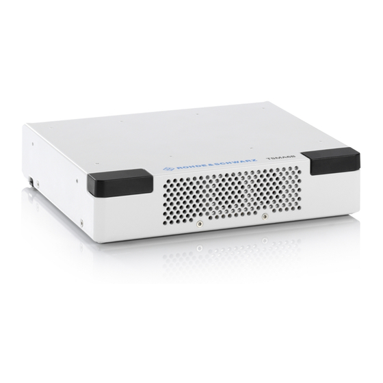
Rear panel view Instrument tour Front panel view The front panel of the R&S TSMA6B does not provide any connectors or control elements for operation. The black caps on the left and right contain the WLAN antennas. Figure 5-1: R&S TSMA6B - Front Panel... - Page 34 The SCAN port provides a high-speed 1 Gbit Ethernet interface with an RJ 45 connector. It is used to connect the R&S TSMA6B to a separate R&S TSME6 as a second scanner used for MIMO scenarios and for increasing bandwidth and measurement rate.
- Page 35 ● Input/output: Synchronization with up to 4 connected R&S TSME6 resp. R&S TSMExxDC (requires sync cable R&S TSME6-ZC2, R&S no. 4900.1800.02 or R&S TSME6-ZC4, R&S no. 4900.1817.02) ● Input: Synchronization of R&S TSMA6B with an external 10 MHz reference (requires dedicated sync cable) USB 3.0 (5x, Type A) Connecting external storage devices, data sticks and test mobile phones.
- Page 36 System recovery to factory or user default. Use a slim, dull object for pressing the button. Min button hold time for detection: 20 sec Status LEDs - Mode, Meas The status LEDs [Mode] and [Meas] indicate different states of the R&S TSMA6B. For a detailed description, see Chapter 5.6, "Status LEDs", on page 41.
-
Page 37: Removable Ssd Option (R&S Tsma6B-Beb)
The R&S TSMA6B can be ordered with a removable SSD option. With this option, the system disk (SSD) is mounted in an external SSD enclosure and connected via the USB3.1 port of the R&S TSMA6B. There is no internal disk assembled / fitted when ordered with this hardware option.. -
Page 38: Built-In Gps Receiver
Built-In GPS receiver Figure 5-3: R&S TSMA6B - removable disk option 1 = External enclosure with SSD hard disc 2 = USB connection between R&S TSMA6B and SSD hard disc For removing the external disk from the enclosure, see Chapter 4.12, "Using external SSD option (R&S... -
Page 39: Built-In Wlan / Bluetooth Adapter
● Client connection to a distant WLAN network ● Serving as a WLAN access point Per default, the R&S TSMA6B WLAN access point is switched on. The login cre- dentials are found on the bottom label of the device. The WLAN / Bluetooth can be switched off (flight mode) via rear panel switch. - Page 40 ® Instrument tour R&S TSMA6B Built-In WLAN / Bluetooth adapter & Schwarz are not liable for any damage or violation of government regulations that may arise from the user failing to comply with these guidelines. This wireless adapter complies with Part 15 of the FCC Rules and with Industry Canada license-exempt RSS standard(s).
-
Page 41: Status Leds
® Instrument tour R&S TSMA6B Status LEDs Usage in specific environments ● The use of wireless adapters in hazardous locations is limited by the con- straints posed by the safety directors of such environments. ● The use of wireless adapters in hospitals is restricted to the limits set forth by each hospital. - Page 42 ® Instrument tour R&S TSMA6B Status LEDs ● [Meas] Indicates the state of the SW application Device Scanner [Mode] LED [Meas] LED [Pwr] LED [State]LED Comment Power Off green (BLINK- Power On ING, 1 Hz) Selftest / Power Down green (CONT.) ---...
- Page 43 ® Instrument tour R&S TSMA6B Status LEDs Device Scanner [Mode] LED [Meas] LED [Pwr] LED [State]LED Comment red (BLINKING, 2 Scanner Error Temperature Warning red (CONT.) Scanner Error Temperature Error red (BLINKING rap- SW error idly) Getting Started 4901.4010.02 ─ 02...
- Page 44 ® Instrument tour R&S TSMA6B Status LEDs Getting Started 4901.4010.02 ─ 02...
-
Page 45: Configuring The R&S Tsma6B
There are different ways to control measurements on the R&S TSMA6B. ● Local operation To use the R&S TSMA6B as an ordinary PC, an external monitor, mouse and keyboard have to be connected to the R&S TSMA6B. ● Remote access The remote access to the R&S TSMA6B can be realized via the following... -
Page 46: Local Use Of The Web Gui
Configuring the R&S TSMA6B R&S TSMA6B Accessing the R&S TSMA6B To access the R&S TSMA6B web GUI, use one of the following options. 6.1.1.1 Local use of the web GUI 1. Connect a mouse, a keyboard and a monitor to the R&S TSMA6B. -
Page 47: Using A Remote Desktop Connection
If you connect the R&S TSMA6B LAN interface with a PC via LAN cable, the IP addresses are negotiated automatically by default. The IP address of the R&S TSMA6B can be read from the local web GUI (see Chapter 6.1.1, "Using the R&S TSMA6B web GUI",... - Page 48 R&S TSMA6B Accessing the R&S TSMA6B 6. Click "Connect". 7. Enter the password (default: 894129) and click "OK". 8. The remote desktop connection is established. The R&S TSMA6B can be controlled from the remote PC. Getting Started 4901.4010.02 ─ 02...
-
Page 49: Selecting Mode Of Operation
The CPU switch must be in normal mode (see Chapter 4.5.1, "Normal mode", on page 23). Select the measurement mode with the following steps. 1. Start the R&S TSMA6B web GUI (see Chapter 6.1.1, "Using the R&S TSMA6B web GUI", on page 45). -
Page 50: Measurement Modes
A Remote ViCom client application needs to be installed on the handheld device for this purpose. The connection between the Remote ViCom server on the R&S TSMA6B and the client application (Remote ViCom client) on the handheld device can be realized ®... -
Page 51: Qualipoc Mode
Selecting mode of operation Measurement with the rViCom sample App To run measurements, the requirements for operating the rViCom sample App have to be fulfilled, see R&S TSMA6B user manual. 1. Activate the rViCom server mode (see Chapter 6.2, "Selecting mode of opera- tion",... - Page 52 ® Configuring the R&S TSMA6B R&S TSMA6B Selecting mode of operation ® 3. On the handheld device, start the QualiPoc application. 4. Touch the main menu , and then touch "Device manager" 5. Touch the plus sign (+) at the top of the screen and touch "NCM".
- Page 53 TSMA6B Selecting mode of operation Figure 6-2: Scan for NCM 7. Touch "[Disconnected]", touch the TSMA6B scanner in the list, for example, "TSMA6B-900012", and then touch "OK" to accept the pairing request. Figure 6-3: Pair NCM Figure 6-4: Bluetooth pairing request 8.
-
Page 54: Nestor And Nestor Probe Mode
R&S TSMA6B. ● NESTOR probe mode The R&S TSMA6B hosts only the NESTOR measurement engine. The NES- TOR UI engine is hosted on a remote PC connected via LAN/WLAN with the R&S TSMA6B. This master PC is required to control the measurement. - Page 55 – optional: NESTOR license dongle connected to a USB port NESTOR mode To use the R&S TSMA6B NESTOR mode, the following steps must be performed. 1. In the web-GUI, set the "Mode of Operation" to "NESTOR". 2. Select a NESTOR workspace file.
-
Page 56: Smartone Mode
The SmartONE modes are only displayed if SmartONE software is installed (see R&S TSMA6B user manual). To use the R&S TSMA6B with R&S SmartONE, the following steps must be per- formed. 1. In the web GUI, set the "Mode of Operation" to one of the following SmartONE modes and press "Submit". - Page 57 ® Configuring the R&S TSMA6B R&S TSMA6B Selecting mode of operation 2. Configure the additional settings for "SmartONE Expert" mode only. ● Autostart R&S SmartONE Expert is automatically started in this mode with a work- space file. The workspace file need to be selected via the drop-down menu.
-
Page 58: Importing Workspace Files (Nestor, Smartone Expert)
TSMA6B Importing workspace files (NESTOR, SmartONE Expert) Importing workspace files (NESTOR, SmartONE Expert) Import NESTOR workspace file 1. Start the R&S TSMA6B web GUI from the host PC (see Chapter 6.1.1, "Using the R&S TSMA6B web GUI", on page 45). -
Page 59: Pairing Bluetooth ® Devices
ROMES mode. ® Pairing Bluetooth devices To pair the R&S TSMA6B with a remote device, the following steps must be per- formed. ® For Bluetooth preparation, the device must be in the "PC Mode". Check it via the web GUI ("Home"... - Page 60 7. On the remote device, confirm the Bluetooth pairing code. Changing keyboard language ® By default, the R&S TSMA6B is delivered with the English version of Windows 10 and it supports the English keyboard. To use the german keyboard (or any other one), proceed as follows.
- Page 61 ® Configuring the R&S TSMA6B R&S TSMA6B Changing keyboard language 2. Select "Add a language" under " Clock, Language, and Region". 3. The "Language" settings window opens and by default only English is listed there. To add a new language, click the "Add a language" tile.
- Page 62 ® Configuring the R&S TSMA6B R&S TSMA6B Changing keyboard language 4. The selectable languages are listed. Select the desired language by double- clicking the language tile (in the example German is selected). 5. Next, select the version of the chosen language.
- Page 63 Configuring the R&S TSMA6B R&S TSMA6B Verify virtual memory settings Verify virtual memory settings To enable virtual memory on the R&S TSMA6B, perform the following steps: 1. Open "Settings". 2. In the "Settings", select "System". Getting Started 4901.4010.02 ─ 02...
- Page 64 ® Configuring the R&S TSMA6B R&S TSMA6B Verify virtual memory settings 3. In "Systems", select "About". Getting Started 4901.4010.02 ─ 02...
- Page 65 ® Configuring the R&S TSMA6B R&S TSMA6B Verify virtual memory settings 4. Select "System info". 5. Select "Advanced System Settings". Getting Started 4901.4010.02 ─ 02...
- Page 66 ® Configuring the R&S TSMA6B R&S TSMA6B Verify virtual memory settings 6. Select the tab "Advanced". 7. Select "Settings..." in the section "Performance". 8. Select the tab "Advanced". Getting Started 4901.4010.02 ─ 02...
- Page 67 ® Configuring the R&S TSMA6B R&S TSMA6B Verify virtual memory settings 9. Select "Change..." in the section "Virtual memory". 10. Enable "Automatically manage paging file size for all devices". 11. Click "OK" to close the dialog. 12. Reboot the device.
- Page 68 ® Configuring the R&S TSMA6B R&S TSMA6B Verify virtual memory settings Getting Started 4901.4010.02 ─ 02...
- Page 69 ® Contacting customer support R&S TSMA6B Contacting customer support Technical support – where and when you need it For quick, expert help with any Rohde & Schwarz product, contact our customer support center. A team of highly qualified engineers provides support and works with you to find a solution to your query on any aspect of the operation, program- ming or applications of Rohde &...
- Page 70 ® Contacting customer support R&S TSMA6B Getting Started 4901.4010.02 ─ 02...
Need help?
Do you have a question about the TSMA6B and is the answer not in the manual?
Questions and answers