R&S TSMA6 Series User Manual
Autonomous mobile network scanner
Hide thumbs
Also See for TSMA6 Series:
- User manual (190 pages) ,
- Getting started (51 pages) ,
- Manual (10 pages)
Table of Contents
Advertisement
Quick Links
Advertisement
Table of Contents

Related Manuals for R&S TSMA6 Series


Summary of Contents for R&S TSMA6 Series
- Page 1 ® R&S TSMA6 Autonomous Mobile Network Scanner User Manual (a0ÞÇ2) 4900805702...
- Page 2 ® This manual describes the following R&S TSMA6 models: ● ® R&S TSMA6 (4900.8005.02) © 2020 Rohde & Schwarz GmbH & Co. KG Mühldorfstr. 15, 81671 München, Germany Phone: +49 89 41 29 - 0 Fax: +49 89 41 29 12 164 Email: info@rohde-schwarz.com Internet:...
-
Page 3: Table Of Contents
® Contents R&S TSMA6 Contents 1 Preface....................9 Documentation Overview..................... 9 1.1.1 Getting Started Manual....................9 1.1.2 User Manuals and Help....................9 1.1.3 Basic Safety Instructions....................9 1.1.4 Data Sheets and Brochures.................... 9 1.1.5 Release Notes and Open Source Acknowledgment (OSA)..........9 Safety and Regulatory Information................ - Page 4 ® Contents R&S TSMA6 Connecting USB to LAN Adapter TSPC-U2L2 / TSPC-USL........30 Connecting Test Mobile Phones................30 Enabling Untethered Dead Reckoning ..............31 6 Configuring the R&S TSMA6...............32 Accessing the R&S TSMA6..................32 6.1.1 Start the R&S TSMA6 Web GUI..................32 6.1.2 Establish a Remote Desktop Connection..............33 Selecting Measurement Mode..................35...
- Page 5 ® Contents R&S TSMA6 7.2.1.4 ViCom Server Installation Using a USB Stick............... 68 7.2.2 R&S NESTOR Software....................69 7.2.2.1 Preparation........................69 7.2.2.2 NESTOR Local Installation....................70 7.2.2.3 NESTOR Remote Installation..................70 7.2.2.4 NESTOR Installation Using a USB Stick...............71 7.2.3 SwissQual DiversityProbe for QualiPoc Software............72 7.2.3.1 Preparation........................72 7.2.3.2...
- Page 6 ® Contents R&S TSMA6 8 Troubleshooting................... 93 LED Indicated Errors....................93 Evaluate Selftest File....................94 Verify Scanner Link / Recall Device Info Using TsmeDeviceManager....94 8.3.1 Obtaining Device Information - "Device Info"..............95 8.3.2 Device Analysis Output....................96 8.3.3 Verify Installed License Keys..................97 R&S TSMA6 Automatically Switches Off After Power On........
- Page 7 ® Contents R&S TSMA6 A.2.2.3 WLAN AP........................127 A.2.2.4 LAN..........................128 A.2.2.5 Lan Ext.1........................129 File Transfer.......................129 Options........................130 A.4.1 Available........................130 A.4.2 Install...........................131 Update........................132 Backup........................132 Restart........................133 Help..........................134 B Introduction to Remote ViCom Sample App........135 Overview........................135 Requirements......................135 B.2.1 General Requirements....................
- Page 8 ® Contents R&S TSMA6 B.3.6.1 RF Power Scan References..................144 B.3.6.2 RF Power Scan Results....................145 C Managing Scanner Device with R&S TsmeDeviceManger..... 147 Installing and Managing Software License Keys - "Options"....... 147 Configuring Measurement Bands - "Band Configuration"........149 Obtaining Firmware and Correction Data Updates - "Updates"......151 Aligning R&S TSMA6 Manually - "Self Alignment"..........152 Configuring Downconverter R&S TSME30DC/TSME44DC - "Downconverter Con- figuration"........................
-
Page 9: Preface
® Preface R&S TSMA6 Documentation Overview 1 Preface 1.1 Documentation Overview This section provides an overview of the R&S TSMA6 user documentation. Unless specified otherwise, you find the documents on the R&S TSMA6 product page at: www.rohde-schwarz.com/manual/tsmx 1.1.1 Getting Started Manual Introduces the R&S TSMA6 and describes how to set up and start working with the product. -
Page 10: Safety And Regulatory Information
® Preface R&S TSMA6 Safety and Regulatory Information 1.2 Safety and Regulatory Information The product documentation helps you use the R&S TSMA6 safely and efficiently. Fol- low the instructions provided here and in the printed "Basic Safety Instructions". Keep the product documentation nearby and offer it to other users. Intended use The R&S TSMA6 is intended for the development, production and verification of elec- tronic components and devices in industrial, administrative, and laboratory environ-... -
Page 11: Key Features
® Key Features R&S TSMA6 2 Key Features As in-building traffic in cellular networks grows, there is an increased need for indoor measurements. While traditional drive test systems consist of a laptop with test mobile phones and scanners, there are also walk-test solutions that use tablets and smart- phones. -
Page 12: Instrument Tour
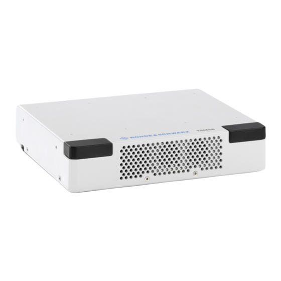
® Instrument Tour R&S TSMA6 Rear Panel View 3 Instrument Tour 3.1 Front Panel View The front panel of the R&S TSMA6 does not provide any connectors or control ele- ments for operation. Figure 3-1: R&S TSMA6 - Front Panel 3.2 Rear Panel View The following figure provides an overview of the control elements and the connectors on the rear panel of the instrument. - Page 13 ® Instrument Tour R&S TSMA6 Rear Panel View WLAN/Bluetooth ON/OFF Switches WLAN and Bluetooth on and off. SCAN (LAN Connector (Gbit)) The LAN connector provides a high-speed 1 Gbit Ethernet interface with an RJ 45 con- nector. It is used to connect the R&S TSMA6 to a separate R&S TSME6 as a second scanner.
- Page 14 ® Instrument Tour R&S TSMA6 Rear Panel View Power ON/OFF The POWER ON/OFF button turns on and off the device. Press and hold the button results in a coldstart of the R&S TSMA6. Restore Press the RESTORE button ( > 20 sec) to bring the system partition of the embedded Windows CPU back to factory default or to a user backup (if created).
-
Page 15: Status Leds
® Instrument Tour R&S TSMA6 Status LEDs The LAN interface can be used for Remote Control / Remote Desktop Connections. Alternatively, it can also be used for distributed applications of R&S NESTOR. The LEDs on the LAN port indicate the status of the connection to the host PC. LED 1 (yellow, link status) is on the left side of the port, LED 2 (green, activity status) is on the right. - Page 16 ® Instrument Tour R&S TSMA6 Status LEDs Device Scanner [Mode] LED [Meas] LED [Pwr] LED [State]LED Comment Power Off green (BLINKING, 1 Power On Selftest / Power Down green (CONT.) Power On / WLAN blue (CONT.) Power On / WLAN green (BLINKING red (Off-On <...
-
Page 17: Option Concept
® Option Concept R&S TSMA6 Technology Options 4 Option Concept The R&S TSMA6 scanner consists of the R&S TSMA6 hardware and a set of (speci- fied) technology and band options when it comes from the factory. 4.1 Technology Options Technology options allow the R&S TSMA6 to scan the input based on a specific tech- nology, for example, LTE. -
Page 18: Band Options
® Option Concept R&S TSMA6 R&S ROMES Options 4.2 Band Options The R&S TSMA6 hardware simultaneously measures in all wireless communications bands from 350 MHz to 6 GHz. Using band licenses, more cost-efficient configurations are available for applications where only a limited number of bands need to be mea- sured simultaneously. -
Page 19: Preparing For Use
® Preparing for Use R&S TSMA6 Unpacking the Instrument 5 Preparing for Use Risk of injury and instrument damage The instrument must be used in an appropriate manner to prevent electric shock, fire, personal injury, or damage. ● Do not open the instrument casing. ●... -
Page 20: Connecting External Devices
® Preparing for Use R&S TSMA6 Connecting External Devices Risk of instrument damage due to inappropriate operating conditions Specific operating conditions are required to ensure accurate measurements and to avoid damage to the instrument. Observe the information on appropriate operating conditions provided in the basic safety instructions and the instrument's data sheet. -
Page 21: Connecting Power Supply
® Preparing for Use R&S TSMA6 Connecting Power Supply To select the correct connectors, refer to Chapter 3.2, "Rear Panel View", on page 12. 1. Connect the RF antenna to the RF IN connector (see Figure 3-2 - 14). 2. Connect the GPS antenna to the GPS ANT port (see Figure 3-2 - 4). -
Page 22: Connecting An Ac Power Supply
® Preparing for Use R&S TSMA6 Connecting Power Supply Figure 5-1: Supplied power cable with cigarette lighter adapter 5.3.2 Connecting an AC Power Supply To operate the R&S TSMA6 with an AC power supply, connect the DC IN connector with the AC power supply (R&S TSMA6-Z1, R&S No. 4901.0550.02). Use only the R&S TSMA6-Z1, R&S No. -
Page 23: Connecting The R&S Tsma6-Bp Battery Pack Unit
® Preparing for Use R&S TSMA6 Connecting Power Supply 5.3.3 Connecting the R&S TSMA6-BP Battery Pack Unit Alternatively, it is possible to power the R&S TSMA6 via the R&S TSMA6-BP Battery Pack Unit. To use the R&S TSMA6 with the battery pack, the following steps must be performed. 1. - Page 24 ® Preparing for Use R&S TSMA6 Connecting Power Supply 3. Attach the R&S TSMA6 with the bottom side (see Figure 5-5) on top of the R&S TSMA6-BP (see Figure 5-4). Figure 5-4: R&S TSMA6-BP 1 = Mechanical connectors for R&S TSMA6 2 = Power connector for R&S TSMA6 Figure 5-5: R&S TSMA6 1* = Power connector for R&S TSMA6-BP...
-
Page 25: Switching On R&S Tsma6
® Preparing for Use R&S TSMA6 Switching On R&S TSMA6 Figure 5-6: Connected R&S TSMA6 and R&S TSMA6-BP 1 = Move R&S TSMA6 vertically 2 = Move R&S TSMA6 horizontally 3 = Power Connection established The power-up behavior after connecting the R&S TSMA6-BP Battery Pack Unit (including charged batteries or connected to an external DC power supply) with the R&S TSMA6 depends on the system settings on the R&S TSMA6 (see Chapter A. -
Page 26: Connecting With R&S Tsma6 Wlan Access Point
® Preparing for Use R&S TSMA6 Connecting with R&S TSMA6 WLAN Access Point 5.5 Connecting with R&S TSMA6 WLAN Access Point 5.5.1 Windows 7 1. Click the Network symbol in the task bar. 2. Select the correct WLAN (in this example: TSMA6-101084). 3. -
Page 27: Windows 10
® Preparing for Use R&S TSMA6 Connecting with R&S TSMA6 WLAN Access Point Default security key: instrument The connection to the WLAN access point is established. 5.5.2 Windows 10 1. Click the Network symbol in the task bar. 2. Select the correct WLAN (in this example: TSMA6-101084). User Manual 4900.8057.02 ─... - Page 28 ® Preparing for Use R&S TSMA6 Connecting with R&S TSMA6 WLAN Access Point 3. Select "Connect automatically" and click "Connect". 4. Select "Connect using a security key instead". User Manual 4900.8057.02 ─ 06...
- Page 29 ® Preparing for Use R&S TSMA6 Connecting with R&S TSMA6 WLAN Access Point 5. Enter the network security key and click "Next". Default security key: instrument User Manual 4900.8057.02 ─ 06...
-
Page 30: Connecting Usb To Lan Adapter Tspc-U2L2 / Tspc-Usl
® Preparing for Use R&S TSMA6 Connecting Test Mobile Phones The connection to the WLAN access point is established. 5.6 Connecting USB to LAN Adapter TSPC-U2L2 / TSPC- Currently following LAN adapters are available. ● Dual Gbit LAN port adapter TSPC-U2L2 ●... -
Page 31: Enabling Untethered Dead Reckoning
® Preparing for Use R&S TSMA6 Enabling Untethered Dead Reckoning To connect other test mobiles, refer to the R&S ROMES User Manual. 5.8 Enabling Untethered Dead Reckoning The following steps are necessary to enable untethered dead reckoning with the inte- grated receiver (see "GPS Ant."... -
Page 32: Configuring The R&S Tsma6
® Configuring the R&S TSMA6 R&S TSMA6 Accessing the R&S TSMA6 6 Configuring the R&S TSMA6 6.1 Accessing the R&S TSMA6 There are different ways to control measurements on the R&S TSMA6. ● Local operation To use the R&S TSMA6 as an ordinary PC, an external monitor, mouse and key- board have to be connected to the R&S TSMA6. -
Page 33: Establish A Remote Desktop Connection
® Configuring the R&S TSMA6 R&S TSMA6 Accessing the R&S TSMA6 1. Connect the R&S TSMA6 LAN port with the host PC port. 2. Use the R&S TSMA6 default IP settings, that is, the DHCP client. The R&S TSMA6 and the remote host PC automatically negotiate the IP address. Alternatively, use the fixed address. - Page 34 ® Configuring the R&S TSMA6 R&S TSMA6 Accessing the R&S TSMA6 5. Click "Connect". 6. Enter the password 894129 and click "OK". 7. The remote desktop connection is established. The R&S TSMA6 can be controlled by a standard Windows PC. User Manual 4900.8057.02 ─...
-
Page 35: Selecting Measurement Mode
® Configuring the R&S TSMA6 R&S TSMA6 Measurement Modes 6.2 Selecting Measurement Mode Select the measurement mode with the following steps. 1. Check the prerequisites of the desired measurement mode (see Chapter 6.3, "Measurement Modes", on page 35) and adjust your device according to these requirements. -
Page 36: Pc Mode
® Configuring the R&S TSMA6 R&S TSMA6 Measurement Modes The "rViCom" and"PC Mode" are selectable on all the R&S TSMA6s. The other modes (NESTOR, ROMES, QualiPoc) are only selectable if the appropriate SW applications are installed (see Chapter 7.2, "Software Installation", on page 65). -
Page 37: Qualipoc Mode
® Configuring the R&S TSMA6 R&S TSMA6 Measurement Modes b) Start the rViCom Sample App on the mobile device. For more details, see Chapter B.3, "Usage", on page 136. 6.3.3 QualiPoc Mode The QualiPoc mode is only displayed if the QualiPoc setup has been executed (see )Chapter 7.2.3, "SwissQual DiversityProbe for QualiPoc Software",... - Page 38 ® Configuring the R&S TSMA6 R&S TSMA6 Measurement Modes ® QualiPoc displays "NCM" under Devices. ® Note: The NCM provides the Bluetooth connection to the scanner. 6. Touch "Scan" at the top of the screen and wait until the scanning process stops. Figure 6-2: Scan for NCM 7.
-
Page 39: Nestor And Nestor Probe Mode
® Configuring the R&S TSMA6 R&S TSMA6 Measurement Modes Figure 6-4: Bluetooth pairing request 8. The scanner appears in the "Devices" list upon successful detection. Figure 6-5: Scanner ready For more details about the QualiPoc configuration and usage, refer to the user docu- ®... - Page 40 ® Configuring the R&S TSMA6 R&S TSMA6 Measurement Modes ● For NESTOR mode only: – NESTOR workspace file imported (see "Import NESTOR workspace file" on page 42 ● For NESTOR Probe mode only: – WLAN / LAN connection with the NESTOR host (see Chapter 6.1, "Accessing the R&S TSMA6",...
-
Page 41: Romes Mode
® Configuring the R&S TSMA6 R&S TSMA6 Measurement Modes 4. Press "Submit". The R&S TSMA6 is switched into "NESTOR" mode. In the status bar, the entry is "Changing mode of operation in progress...". The mode switch is finished when the status bar indicates "No error". The scanner state LED starts blinking rapidly. -
Page 42: Import Of Workspace Files (Nestor, Romes)
® Configuring the R&S TSMA6 R&S TSMA6 Import of Workspace Files (NESTOR, ROMES) 2. Configure the following settings. ● Workspace File In the drop-down menu, select a ROMES workspace file (see "Import of ROMES Workspace File" on page 43). ● Recording Activating this checkbox, the ROMES measurement data are written to the TSMA6 hard disk. -
Page 43: Bluetooth ® Pairing
® Configuring the R&S TSMA6 R&S TSMA6 ® Bluetooth Pairing The file is copied to the NESTOR workspace directory (default: D:\Users\Instrument\Documents\NESTOR\FavoriteWorkspaces). This path can be configured in the "File Transfer" menu. 7. Navigate back to "Configuration" > "System" > "Mode". 8. -
Page 44: Changing Password Of R&S Tsma6
® Configuring the R&S TSMA6 R&S TSMA6 Changing Password of R&S TSMA6 Figure 6-6: Bluetooth settings 2. Navigate to "Configuration" > "Connectivity" > "Bluetooth" and verify the settings: ● STATUS = On ● Visibility = Visible If necessary, change the settings via the buttons on the right. 3. - Page 45 ® Configuring the R&S TSMA6 R&S TSMA6 Changing Password of R&S TSMA6 Change Password 1. On R&S TSMA6, open the "Control Panel". 2. Navigate to "User Accounts" > "Change account type". 3. In the following window, double-click the account "instrument" to edit the settings. 4.
- Page 46 ® Configuring the R&S TSMA6 R&S TSMA6 Changing Password of R&S TSMA6 Enable Autologin After changing the password, change the password also in "Autologin" settings. To change the "Autologin" settings, proceed as follows. 1. Open the "Registry Editor". 2. In the "Registry Editor", navigate to HKEY_LOCAL_MACHINE\SOFTWARE\Microsoft\Windows NT\ CurrentVersion\Winlogon (1) and double-click the parameter "Default Pass- word"...
-
Page 47: Changing Keyboard Language
® Configuring the R&S TSMA6 R&S TSMA6 Changing Keyboard Language 3. The "Edit the default password" window is opening. Under "Value data", type in the new password. 4. Click "OK". The changes are accepted. After powering, the R&S TSMA6 automati- cally login. - Page 48 ® Configuring the R&S TSMA6 R&S TSMA6 Changing Keyboard Language 2. Select "Add a language" under "Clock, Language, and Region". 3. The "Language" settings window opens and by default only English is listed there. To add a new language, click the "Add a language" tile. User Manual 4900.8057.02 ─...
-
Page 49: Enable Virtual Memory
® Configuring the R&S TSMA6 R&S TSMA6 Enable Virtual Memory 4. The selectable languages are listed. Select the desired language by double-click- ing the language tile (in the example German is selected). 5. Next, select the version of the chosen language. 6. - Page 50 ® Configuring the R&S TSMA6 R&S TSMA6 Enable Virtual Memory 2. Select "System and Security". 3. Select "Advanced System Settings". User Manual 4900.8057.02 ─ 06...
- Page 51 ® Configuring the R&S TSMA6 R&S TSMA6 Enable Virtual Memory 4. Select the tab "Advanced". 5. Select "Settings..." in the section "Performance". 6. Select the tab "Advanced". User Manual 4900.8057.02 ─ 06...
- Page 52 ® Configuring the R&S TSMA6 R&S TSMA6 Enable Virtual Memory 7. Select "Change..." in the section "Virtual memory". 8. Enable "Automatically manage paging file size for all devices". 9. Click "OK" to close the dialog. 10. Reboot the device. User Manual 4900.8057.02 ─ 06...
-
Page 53: Update And Restore
® Update and Restore R&S TSMA6 Firmware Update 7 Update and Restore 7.1 Firmware Update 7.1.1 Preparing Installation Firmware update packages for the R&S TSMA6 can be downloaded from the Rohde & Schwarz web page https://www.rohde-schwarz.com/us/firmware/tsmx/. The firmware setup file can be found under the title R&S TSMAx Firmware V ww.xx.yy.zz. There are several ways how to install firmware and software components on the R&S TSMA6. - Page 54 ® Update and Restore R&S TSMA6 Firmware Update 7. The package dialog lists all the available packages in the setup. Normally, this dia- log can be skipped without any changes. Select "Automatic Reboot". 8. Press "Install >". Note: Do not switch off or unplug from power while running firmware/software update.
-
Page 55: Remote Installation Of The Setup File
® Update and Restore R&S TSMA6 Firmware Update 9. Finally, when all firmware/software packages are installed, a restart is executed. 10. When the R&S TSMAx firmware comes up again, the mainboard firmware is upda- ted. Note: Step step 10 step 11 are only performed during firmware update, if the firmware package contains a new mainboard firmware. - Page 56 ® Update and Restore R&S TSMA6 Firmware Update a) Using LAN Connection ● Connect the LAN port of the R&S TSMA6 with the host PC LAN port. The LAN port is marked with the LAN symbol. The default IP setting of this port is "DHCP client". For details on how to configure the remote PC, contact your network administrator.
- Page 57 ® Update and Restore R&S TSMA6 Firmware Update 4. Select "Remote Installation" and click "Next>". 5. The package dialog list all the available packages to install. All packages, which you need to install are already pre-selected. 6. Click "Next>". 7. After a while, all R&S TSMA6 devices in the network are listed in the "Device List" dialog.
-
Page 58: Installation Using A Usb Stick
® Update and Restore R&S TSMA6 Firmware Update 8. Click "Install". Note: Do not switch off or unplug from power while running firmware/software update. 9. The state of the installation process is displayed in the "Status" column. The proc- ess is finished when the status indicates "Ready…". 10. - Page 59 ® Update and Restore R&S TSMA6 Firmware Update 2. Switch on the R&S TSMA6 via power button. 3. Copy the setup file onto a USB memory stick. a) For firmware installation: Copy the firmware setup file TSMAx-Setup-<Version>.exe into the root directory of the stick. b) For software installation: Copy the corresponding setup file into the root direc- tory of the stick.
- Page 60 ® Update and Restore R&S TSMA6 Firmware Update next to the select box. 7. A confirmation dialog appears. Confirm with "OK" to start the update. 8. The firmware/software installation starts. The status text in the web GUI displays "Installation in progress…". The mode LED starts blinking blue.
- Page 61 ® Update and Restore R&S TSMA6 Firmware Update 11. About one minute after the operating system is up again, the flash of the main- board firmware starts. The microcontroller flash is indicated like following: Meas LED = red, mode LED = off Fans are switched to full speed.
-
Page 62: Calling R&S Tsma6 Web Gui
® Update and Restore R&S TSMA6 Firmware Update 7.1.3 Calling R&S TSMA6 Web GUI The R&S TSMA6 web GUI has to be loaded prior to executing firmware / software setup. ● Remote from a WLAN connected device Start the web browser and enter the following URL: http://192.168.137.1 ●... -
Page 63: Checking Mode Of Operation
® Update and Restore R&S TSMA6 Firmware Update 7.1.4 Checking Mode of Operation In order to execute the setup on the R&S TSMA6, the mode of operation has to be "PC Mode". 1. Open the R&S TSMA6 web GUI. Use one of the following options. ●... - Page 64 ® Update and Restore R&S TSMA6 Firmware Update 3. If a different mode is activated, navigate to "Configuration" > "System" > "Mode", select the "PC Mode" and press the "Submit" button. User Manual 4900.8057.02 ─ 06...
-
Page 65: Software Installation
® Update and Restore R&S TSMA6 Software Installation 4. Reload the web GUI after changing the mode, and ensure that the "Mode of Oper- ation" is "PC Mode". The R&S TSMA6 is ready for firmware update / software installation. 7.2 Software Installation Following software components are available for installation on the R&S TSMA6. -
Page 66: Remote Vicom Server Software
® Update and Restore R&S TSMA6 Software Installation 7.2.1 Remote ViCom Server Software The Remote ViCom Server (rViCom) is an additional software package for the R&S TSMA6. The latest version of this package is pre-installed on any shipped R&S TSMA6. An upgrade of the Remote ViCom package is "only"... -
Page 67: Vicom Server Remote Installation
® Update and Restore R&S TSMA6 Software Installation 3. All subsequent steps are similar to local firmware installation, see Chapter 7.1.2.1, "Local Execution of the Setup File", on page 53, step 7 and following. Do not switch off or unplug from power while running firmware/software update. 7.2.1.3 ViCom Server Remote Installation Follow the general instructions in... -
Page 68: Vicom Server Installation Using A Usb Stick
® Update and Restore R&S TSMA6 Software Installation 3. All subsequent steps are similar to remote firmware installation, see Chap- ter 7.1.2.2, "Remote Installation of the Setup File", on page 55, step 4 and follow- ing. 7.2.1.4 ViCom Server Installation Using a USB Stick Follow the general instructions in Chapter 7.1.2.3, "Installation Using a USB Stick",... -
Page 69: R&S Nestor Software
® Update and Restore R&S TSMA6 Software Installation 2. The following steps are similar to the installation using a USB stick, see Chap- ter 7.1.2.3, "Installation Using a USB Stick", on page 58, step 7 step 7.2.2 R&S NESTOR Software This software package is pre-installed at delivery when the R&S TSMA6 is ordered with NESTOR TSMA6 option. -
Page 70: Nestor Local Installation
® Update and Restore R&S TSMA6 Software Installation 7.2.2.2 NESTOR Local Installation Follow the general instructions in Chapter 7.1.2.1, "Local Execution of the Setup File", on page 53, step 1 step 1. Open the Windows Explorer and execute the NESTOR setup file "TSMAx_NES- TOR_Setup-<Version>.exe". -
Page 71: Nestor Installation Using A Usb Stick
® Update and Restore R&S TSMA6 Software Installation 3. All subsequent steps are similar to remote firmware installation, see Chap- ter 7.1.2.2, "Remote Installation of the Setup File", on page 55, step 4 and follow- ing. 7.2.2.4 NESTOR Installation Using a USB Stick Follow the general instructions in Chapter 7.1.2.3, "Installation Using a USB Stick",... -
Page 72: Swissqual Diversityprobe For Qualipoc Software
® Update and Restore R&S TSMA6 Software Installation 2. The following steps are similar to the installation using a USB stick, see Chap- ter 7.1.2.3, "Installation Using a USB Stick", on page 58, step 7 step 7.2.3 SwissQual DiversityProbe for QualiPoc Software Version 15.2.0.25 or greater must be installed on the R&S TSMA6. -
Page 73: Diversityprobe For Qualipoc Local Installation
® Update and Restore R&S TSMA6 Software Installation 7.2.3.2 DiversityProbe for QualiPoc Local Installation Follow the general instructions in Chapter 7.1.2.1, "Local Execution of the Setup File", on page 53, step 1 step 1. Open the Windows Explorer and execute the QualiPoc setup file DiversityProbe4QP-DeploymentKit-<Version>.exe. -
Page 74: Diversityprobe For Qualipoc Installation Using A Usb Stick
® Update and Restore R&S TSMA6 Software Installation 3. All subsequent steps are similar to remote firmware installation, see Chap- ter 7.1.2.2, "Remote Installation of the Setup File", on page 55, step 4 and follow- ing. 7.2.3.4 DiversityProbe for QualiPoc Installation Using a USB Stick Follow the general instructions in Chapter 7.1.2.3, "Installation Using a USB Stick",... -
Page 75: R&S Romes Setup
® Update and Restore R&S TSMA6 Software Installation 2. The following steps are similar to the installation using a USB stick, see Chap- ter 7.1.2.3, "Installation Using a USB Stick", on page 58, step 7 step 7.2.4 R&S ROMES Setup Only execute the dedicated ROMES setup for R&S TSMA6. -
Page 76: Romes Local Installation
® Update and Restore R&S TSMA6 Software Installation 2. Choose the way of installation and follow the instructions how to prepare. 7.2.4.2 ROMES Local Installation Follow the general instructions in Chapter 7.1.2.1, "Local Execution of the Setup File", on page 53, step 1 step 1. -
Page 77: Romes Installation Using A Usb Stick
® Update and Restore R&S TSMA6 Software Installation 3. All subsequent steps are similar to remote firmware installation, see Chap- ter 7.1.2.2, "Remote Installation of the Setup File", on page 55, step 4 and follow- ing. 7.2.4.4 ROMES Installation Using a USB Stick Follow the general instructions in Chapter 7.1.2.3, "Installation Using a USB Stick",... -
Page 78: Options (Nestor, Tsma6, Romes)
® Update and Restore R&S TSMA6 Options (NESTOR, TSMA6, ROMES) 2. The following steps are similar to the installation using a USB stick, see Chap- ter 7.1.2.3, "Installation Using a USB Stick", on page 58, step 7 step 7.3 Options (NESTOR, TSMA6, ROMES) The device must be in the PC Mode. -
Page 79: Installation Of Tsma6 Options
® Update and Restore R&S TSMA6 User Backup and Restore 1. Start the web GUI of the R&S TSMA6. 2. Navigate to "Options" > "Install" Tab (see "Install NESTOR Options" on page 131). 3. Add the license key code of a specific NESTOR option in the field "Install NESTOR Options"... -
Page 80: Restore
® Update and Restore R&S TSMA6 User Backup and Restore The backup procedure takes up to 15 minutes. During the backup the [Mode] LED is blinking red. In the web GUI, the following status message will be displayed. Backup is in progress... The backup procedure has finished, when the [Mode] LED displays the normal operat- ing state. -
Page 81: Master Image
® Update and Restore R&S TSMA6 Master Image 1. Connect mouse, keyboard and monitor to the R&S TSMA6. 2. Press the [Shift] key and reboot the operating system. 3. The R&S TSMA6 reboots in the R&S recovery environment. 4. Select "Factory Default Restore". 5. -
Page 82: Prepare A Tsma6 Image Stick / Tsma6 Recovery Stick
® Update and Restore R&S TSMA6 Master Image Figure 7-1: TSMA6 Master Image - General Overview 7.5.1 Prepare a TSMA6 Image Stick / TSMA6 Recovery Stick The following steps must be done only once. To create a TSMA6 Image Stick you need the following: ●... - Page 83 ® Update and Restore R&S TSMA6 Master Image 2. Open the Windows explorer. 3. Select the USB device. 4. Open the context menu with a right-mouse click and select "Format". The formatting of the stick starts. When the formatting has finished, continue with the following procedure to make the USB stick bootable.
- Page 84 ® Update and Restore R&S TSMA6 Master Image Figure 7-3: USB Stick drive and partition selection 4. To see the available partition of the selected drive use the list partition com- mand. The list of partitions appears. 5. Select the drive's partition. Use the select partition 1 command. 6.
-
Page 85: Copy File Contents On The Usb Stick (Image Stick)
® Update and Restore R&S TSMA6 Master Image 7.5.1.2 Copy File Contents on the USB Stick (Image Stick) 1. Copy ImageStick_<version>.zip in the root directory of the prepared USB stick, which will be used as TSMA6 Image Stick. 2. Select the zip-file and open the context menu with a right-mouse button click. The menu opens automatically. -
Page 86: Capture A Tsma6 Image (Tsma6 Image Stick)
® Update and Restore R&S TSMA6 Master Image 7.5.3 Capture a TSMA6 Image (TSMA6 Image Stick) The capture of the image (partitions are GRUB, SSYTEM, DATA, BACKUP) takes around 15 minutes with USB 3.0 stick and even longer with USB 2.0 stick. As a prerequisite, a user backup must exist on the master device (see Chapter 7.4.1, "Backup",... - Page 87 ® Update and Restore R&S TSMA6 Master Image Figure 7-6: TSMA6 Image Stick menu 4. When the Status has changed to "Finished", click "OK" and then "Reboot". Figure 7-7: TSMA6 Image Stick - Image capturing finished User Manual 4900.8057.02 ─ 06...
- Page 88 ® Update and Restore R&S TSMA6 Master Image Figure 7-8: TSMA6 Image Stick menu - Reboot 5. Remove the TSMA6 Image Stick. The R&S TSMA6 will be rebooted. Figure 7-9: Rebooting R&S TSMA6 User Manual 4900.8057.02 ─ 06...
-
Page 89: Create A Tsma6 Recovery Stick
® Update and Restore R&S TSMA6 Master Image The captured image files (BACKUP.wim, DATA.wim, GRUB.wim, SYSTEM.wim) are stored on the TSMA6 Image Stick in the directory \Device\Images. Figure 7-10: Captured Image Files on a TSMA6 Image Stick The TSMA6 Image Stick can now be used as source for the creation of a TSMA6 Recovery Stick (see Chapter 7.5.4, "Create a TSMA6 Recovery Stick",... - Page 90 ® Update and Restore R&S TSMA6 Master Image 3. The "Images" tab offers download and upload of particular image files. Figure 7-11: Selection of a TSMA6 Image for Transfer 4. Use the "Upload" function associated to the file' s directory and select the file you want to transfer.
-
Page 91: Deploy A Tsma6 Image From A Tsma6 Recovery Stick
® Update and Restore R&S TSMA6 Master Image Figure 7-12: File Transfer Finished - "The operation completed successfully" As long as the procedure is running neither the PC should be switched off nor the Recovery Stick removed. 7.5.5 Deploy a TSMA6 image from a TSMA6 Recovery Stick Deployment of a TSMA6 image requires a TSMA6 Recovery Stick containing the four master image files (GRUB.wim, SYSTEM.wim, DATA.wim, RECOVERY.wim). - Page 92 ® Update and Restore R&S TSMA6 Master Image 3. In the "Recovery TSMA6 Progress" window, the current status of the recovery process is displayed. 4. After a successful recovery, remove the TSMA6 recovery stick. 5. The R&S TSMA6 will be rebooted. User Manual 4900.8057.02 ─...
-
Page 93: Troubleshooting
® Troubleshooting R&S TSMA6 LED Indicated Errors 8 Troubleshooting For all troubleshooting procedures, connect keyboard, mouse and a monitor to the R&S TSMA6. ● LED Indicated Errors....................93 ● Evaluate Selftest File....................94 ● Verify Scanner Link / Recall Device Info Using TsmeDeviceManager.... -
Page 94: Evaluate Selftest File
® Troubleshooting R&S TSMA6 Verify Scanner Link / Recall Device Info Using TsmeDeviceManager 8.2 Evaluate Selftest File ● Path: C:\ProgramData\Rohde-Schwarz\TSMA\Selftestresults ● Filename: Selftestresult.txt Entries in the Selftestresult.txt are created during the boot process of the device and every 5 minutes. To open the Selftestresult.txt, proceed as follows. -
Page 95: Obtaining Device Information - "Device Info
® Troubleshooting R&S TSMA6 Verify Scanner Link / Recall Device Info Using TsmeDeviceManager If a connection to a R&S TSMA6 is not possible (for example due to mismatch of sub- netmask configuration), only limited information is displayed. For example, no informa- tion about installed options is available in this case. -
Page 96: Device Analysis Output
® Troubleshooting R&S TSMA6 Verify Scanner Link / Recall Device Info Using TsmeDeviceManager Table 8-1: R&S TSMA6 device information Label Description Device Device Type Type of device (TSME family, TSMA family) Material Number Order number of the R&S TSMA6 Variant Number Precise device type (variant) Serial Number Unique ID of the R&S TSMA6... -
Page 97: Verify Installed License Keys
® Troubleshooting R&S TSMA6 Verify Scanner Link / Recall Device Info Using TsmeDeviceManager available on all tabs, at the bottom of the "R&S TSME Device Manager" window (see Figure 8-1). Depending on their relevance, the messages are assigned to the following categories: ●... -
Page 98: R&S Tsma6 Automatically Switches Off After Power On
® Troubleshooting R&S TSMA6 R&S TSMA6 Automatically Switches Off After Power On Table 8-2: Software license key information Label Description Option Type Band or technology option name Option Material No. Order number of the option Option key Software license key number Privilege Usage type (customer, services, demo) Time Stamp... -
Page 99: Scanner Is Not Found From Software (R&S Romes, R&S Nestor)
® Troubleshooting R&S TSMA6 Scanner Is Not Found from Software (R&S ROMES, R&S NESTOR) ● If not enabled, contact R&S support. 8.5 Scanner Is Not Found from Software (R&S ROMES, R&S NESTOR) To check if the scanner unit is working properly, perform the following steps. User Manual 4900.8057.02 ─... - Page 100 ® Troubleshooting R&S TSMA6 Scanner Is Not Found from Software (R&S ROMES, R&S NESTOR) 1. Check the LEDs of the device (see Chapter 8.1, "LED Indicated Errors", on page 93). ● If an error is indicated, follow the instructions according to the indicated error. ●...
- Page 101 ® Troubleshooting R&S TSMA6 Scanner Is Not Found from Software (R&S ROMES, R&S NESTOR) ● If the "Mode of Operation" != "PC Mode", switch mode to "PC Mode". Restart the R&S TSMA6 via web GUI and check the LEDs, see step ●...
-
Page 102: Verify Scanner Connection Lan Settings
® Troubleshooting R&S TSMA6 Verify Scanner Connection LAN Settings 7. Check in the "Info" tab, if any device is available. ● If the R&S TSMA6 device is found, check the "Device Analysis Output". ● If the R&S TSMA6 device is not found, contact the R&S support. 8. - Page 103 ® Troubleshooting R&S TSMA6 Verify Scanner Connection LAN Settings Figure 8-3: TSMA6Scanner Connection 2. Double-click the "TSMA6 Scanner Connection Int " entry and verify the following settings. ● IP address: 192.168.0.1 (static IP address) ● "Jumbo Packet": 9014 Bytes User Manual 4900.8057.02 ─ 06...
-
Page 104: No Rf / Gps Data
® Troubleshooting R&S TSMA6 No RF / GPS Data 8.7 No RF / GPS Data 1. Check if the RF antenna is connected to the RF port. Figure 8-4: RF Antenna Connector 1 = RF port 2. Check if the GPS antenna is connected to GPS antenna input. Figure 8-5: GPS Antenna Connector 1 = GPS antenna connector Note: Only use the GPS antenna included in the scope of delivery. -
Page 105: No Remote Access Via Lan Port
® Troubleshooting R&S TSMA6 No Remote Access via LAN Port 8.8 No Remote Access via LAN Port If the R&S TSMA6 could not be accessed for remote control or remote desktop session via the LAN port, check following issues: Optical Check 1. - Page 106 ® Troubleshooting R&S TSMA6 No Remote Access via LAN Port Figure 8-6: web GUI - Overview > IP Settings 3. Check the setting of the R&S TSMA6 LAN port (see Figure 8-7). The default set- ting is "DHCP". Figure 8-7: Web GUI - LAN Connection Ping Command The ping command must be executed from the Windows command prompt on the host PC.
- Page 107 ® Troubleshooting R&S TSMA6 No Remote Access via LAN Port 2. Start the ping command. Type in the command-line window ping <IP address of the remote port of the R&S TSMA6 (LAN)> and wait for the answer. If the R&S TSMA6 does not answer, contact the system administrator or the R&S support.
-
Page 108: Wlan Access Point Not Detected By External Pc, Mobile Or Tablet
® Troubleshooting R&S TSMA6 WLAN Access Point Not Detected By External PC, Mobile Or Tablet 8.9 WLAN Access Point Not Detected By External PC, Mobile Or Tablet With the first R&S TSMA6 devices shipped, the WLAN module is configured to use the 2.4 GHz and 5 GHz band. - Page 109 ® Troubleshooting R&S TSMA6 WLAN Access Point Not Detected By External PC, Mobile Or Tablet 4. Verify the IP settings via the web GUI. Navigate to "Home" > "IP Settings". IP address of WLAN AP = 192.168.137.1 5. Verify LAN settings. Under Windows, navigate to "Settings"...
- Page 110 ® Troubleshooting R&S TSMA6 WLAN Access Point Not Detected By External PC, Mobile Or Tablet 6. Verify driver settings. Right click on "TSMA6 WLAN Connection" and open "Properties". Click "Configure" and select tab "Advanced". Check for the following setting: "802.11a/b/g" = "2.4GHz 802.11b/g" If the setting is correct, contact R&S support.
-
Page 111: Web Gui Not Accessible Via Wlan
® Troubleshooting R&S TSMA6 Web GUI not Accessible via WLAN 8.10 Web GUI not Accessible via WLAN If the R&S TSMA6 web GUI is not accessible, perform the following steps to solve the problem. 1. Check if the WLAN AP is activated. ●... -
Page 112: Web Gui Locally Not Accessible
® Troubleshooting R&S TSMA6 Web GUI Locally Not Accessible If the web browser cannot load the web page, continue with step 5. Check the IP address of the WLAN connection on your handheld device. It must be in the subnet 192.168.137.xxx. ●... - Page 113 ® Troubleshooting R&S TSMA6 Web GUI Locally Not Accessible 2. In the Windows "Start" menu, enter "Services" and check the state of the following services. ● R&S TSMA6 running? ● R&S WebServer running? Figure 8-9: R&S TSMA6 Services If both services are running, continue with step 3.
-
Page 114: Slow/Instable Wlan Connection
® Troubleshooting R&S TSMA6 Slow/Instable WLAN Connection If the web GUI cannot be started, a complete restore must be performed (see Chapter 7.4, "User Backup and Restore", on page 79). 8.12 Slow/Instable WLAN Connection If the WLAN connection is slow resp. sometimes interrupted the settings of the WLAN adapter settings need to be checked. - Page 115 ® Troubleshooting R&S TSMA6 Slow/Instable WLAN Connection 4. Select tab "Advanced". 5. Change the property "802.11a/b/g Wireless Mode" to "4. 2.4GHz 802.11 b/g". 6. Change the property "802.11n/ac Wireless Mode" to "802.11n". User Manual 4900.8057.02 ─ 06...
-
Page 116: Bluetooth ® Device Not Detected By R&S Tsma6
® Troubleshooting R&S TSMA6 ® Bluetooth device not detected by R&S TSMA6 ® 8.13 Bluetooth device not detected by R&S TSMA6 ® To detect/connect a Bluetooth device with R&S TSMA6, click "Refresh Device List" in the web GUI. ® If a mobile or tablet is not detected by the R&S TSMA6 as Bluetooth device, the prob- lem is probably the bluetooth visibility of the mobile (or tablet). - Page 117 ® Troubleshooting R&S TSMA6 ® Bluetooth device not detected by R&S TSMA6 3. After choosing the R&S TSMA6, you receive a "Bluetooth pairing request". Click "OK". 4. Open the R&S TSMA6 web GUI and navigate to "Configuration" > "Connectivity" > "Bluetooth".
-
Page 118: Contacting Customer Support
® Troubleshooting R&S TSMA6 Contacting Customer Support 7. Select the mobile device and press "Connect" for coupling the devices. 8.14 Contacting Customer Support Technical support – where and when you need it For quick, expert help with any Rohde & Schwarz product, contact our customer sup- port center. -
Page 119: Annex
® Usage of the Web GUI R&S TSMA6 Home Annex A Usage of the Web GUI To start the web GUI for configuration tasks, open a browser on your PC, tablet PC or smartphone and enter the following URL: http://192.168.137.1/ The web GUI offers the following pages for configuration tasks: ●... - Page 120 ® Usage of the Web GUI R&S TSMA6 Home └ Battery 1......................121 └ Battery 2......................121 └ Battery Life Time...................121 └ Mainboard Temperature................121 Device Info Displays general information about the device. Type ← Device Info Type of instrument Material No. ← Device Info R&S order number of the device Serial No.
-
Page 121: Ip Settings
® Usage of the Web GUI R&S TSMA6 Home Battery 1 ← Battery Info Charging state of battery 1. Battery 2 ← Battery Info Charging state of battery 2. Battery Life Time ← Battery Info Estimated remaining battery life time. Mainboard Temperature ←... - Page 122 ® Usage of the Web GUI R&S TSMA6 Home └ TCXO Date....................122 Module Info......................... 122 └ Controller Board....................122 └ Board.......................123 └ Mainboard..................... 123 └ Batterypack....................123 Down Converter Info....................123 └ Available FW Versions.................. 123 └ Used FW Version..................123 └...
-
Page 123: Configuration
® Usage of the Web GUI R&S TSMA6 Configuration RF Board ← Module Info Serial number and product change index of the RF board. Mainboard ← Module Info Serial number and product change index of the main board. Batterypack ← Module Info Serial number and product change index of the batterypack module (TSMA6-BP). -
Page 124: Mode
® Usage of the Web GUI R&S TSMA6 Configuration ● Mode........................124 ● Power........................124 ● Speaker.........................125 ● Band........................ 125 A.2.1.1 Mode The "Mode" tab displays information about the operation mode and the state of the cur- rent measurement. Mode of Operation...................... -
Page 125: Speaker
® Usage of the Web GUI R&S TSMA6 Configuration Shutdown Settings Configures a shutdown sequence if the R&S TSMA6 is connected to a R&S TSMA6 Battery Pack. Auto Power Off ← Shutdown Settings When activated, the R&S TSMA6 is powered off automatically, if the DC IN power is removed from the connected R&S TSMA6 Battery Pack. -
Page 126: Bluetooth
® Usage of the Web GUI R&S TSMA6 Configuration A.2.2.1 Bluetooth The "Bluetooth" tab is used to configure the settings of the R&S TSMA6 Bluetooth adapter. As well this tab is used for pairing with an external BT device. Bluetooth Connection....................126 └... -
Page 127: Wlan Ap
® Usage of the Web GUI R&S TSMA6 Configuration Subnet Mask (WLAN Client) ← WLAN Adapter Specify the subnet mask for the R&S TSMA6 Default Gateway (WLAN Client) ← WLAN Adapter Specify the default gateway. DNS Servers(s) (WLAN Client) ← WLAN Adapter Specify the DNS server. -
Page 128: Lan
® Usage of the Web GUI R&S TSMA6 Configuration After confirmation the SSID is changed. The following status information is displayed. A.2.2.4 In the "LAN" tab, the LAN settings can be configured. Connection......................128 └ State......................128 └ TCP/IP Mode (LAN)..................128 └... -
Page 129: Lan Ext.1
® Usage of the Web GUI R&S TSMA6 File Transfer A.2.2.5 Lan Ext.1 In the "Ext. LAN" tab, the LAN settings for the additional Gbit LAN interface can be configured. Lan Ext.1 Connection....................129 └ State......................129 └ TCP/IP Mode (Lan Ext.1)................129 └... -
Page 130: Options
® Usage of the Web GUI R&S TSMA6 Options └ User-defined Download................130 Sample App.........................130 └ Download rViCom SampleApp..............130 File Transfer Specifies the properties for upload and download files. Upload ← File Transfer Specifies the file (e.g. workspace file) which should be transferred from a connected device to the R&S TSMA6 (D:\Upload). -
Page 131: Install
® Usage of the Web GUI R&S TSMA6 Options Option Type.........................131 Option Material No...................... 131 Activation Type......................131 Valid From / Valid To....................131 Option Index........................131 Option Type Type of installed license key Option Material No. R&S order number of installed license key Activation Type Activation type of license key (temporary or permanent) Valid From / Valid To... -
Page 132: Update
® Usage of the Web GUI R&S TSMA6 Backup A.5 Update The "Update" window allows to select and update the TSMA6 software and additional software components. Prerequisites for a Firmware/Software Update ● The setup file must be located in the root directory of the data stick. ●... -
Page 133: Restart
® Usage of the Web GUI R&S TSMA6 Restart Backup TSMA6 System Click "Backup" to create a backup of the system partition C:\. ● At first, it is checked, if there is enough memory available for the backup. ● Only one user backup can be created at time. An existing backup will be overwrit- ten after an acknowledgment. -
Page 134: Help
® Usage of the Web GUI R&S TSMA6 Help A.8 Help The "Help" window displays the online help system of the R&S TSMA6. User Manual 4900.8057.02 ─ 06... -
Page 135: B Introduction To Remote Vicom Sample App
® Introduction to Remote ViCom Sample App R&S TSMA6 Requirements B Introduction to Remote ViCom Sample App B.1 Overview The R&S TSMA6 provides an open remote ViCom interface that allows the integration into Windows and Android-based software tools. Via rViCom API, it is possible to con- figure and control TSMA6 scanner measurements from a remote PC / tablet. -
Page 136: Usage
® Introduction to Remote ViCom Sample App R&S TSMA6 Usage 3. Select the Sample App and click "Download". 4. Install the Sample App on the Android device. B.3 Usage B.3.1 Connection Establishment Start the Sample App on the Android device. B.3.1.1 Connection Type Selection To connect to the R&S TSMA6 Remote rViCom Server, it is either possible to use a... - Page 137 ® Introduction to Remote ViCom Sample App R&S TSMA6 Usage Figure B-2: Active Server Discovery 3. If a server is found, the server will be connected and the name of the server is dis- played. Figure B-3: Successful Server Discovery 4.
-
Page 138: Gsm Rssi Scan
® Introduction to Remote ViCom Sample App R&S TSMA6 Usage The following scan types are available: ● GSM RSSI Scan Provides a GSM scan by selecting a band and radio channels ● WCDMA Top-N Pilot Scan Provides an UMTS scan by selecting a frequency band and the UARFCN ●... -
Page 139: Gsm Scan Results
® Introduction to Remote ViCom Sample App R&S TSMA6 Usage 3. Click "Start scan" to start the scan. B.3.2.2 GSM Scan Results The GSM scan result graph displays one column for each channel selected. The height of a column represents the RSSI value (in dBm). Figure B-6: GSM Scan Result View Below the graph the measurement preferences and the status are displayed. -
Page 140: Wcdma Top-N Pilot Scan
® Introduction to Remote ViCom Sample App R&S TSMA6 Usage B.3.3 WCDMA Top-N Pilot Scan B.3.3.1 WCDMA Top-N Pilot Preferences To start a WCDMA scan, the following steps must be performed. 1. Choose a frequency band. The minimum UARFCN of this band is set automatically. Figure B-7: Setting the WCDMA Preferences 2. -
Page 141: Lte Top Signal Scan
® Introduction to Remote ViCom Sample App R&S TSMA6 Usage Figure B-8: WCDMA Scan Result View Below the graph the measurement preferences and the status are displayed. Parameters Displays the configured preferences for the WCDMA scan. Status Displays the measurement duration and the measurement rate. The status button dis- plays the following colored states. -
Page 142: Lte Top Signal Scan Results
® Introduction to Remote ViCom Sample App R&S TSMA6 Usage Figure B-9: Setting the LTE Preferences 2. If necessary, change the EARFCN according to your needs. Note: Due to processing issues, it is not possible to select more than one EARFCN. -
Page 143: Throughput Test Case
® Introduction to Remote ViCom Sample App R&S TSMA6 Usage Status Displays the measurement duration and the measurement rate. The status button dis- plays the following colored states. ● Green The measurement is running and measurement data are received. ● Yellow The measurement is running but no measurement data are received. -
Page 144: Rf Power Scan
® Introduction to Remote ViCom Sample App R&S TSMA6 Usage ● y-axis The y-axis displays the corresponding throughput value (kB/s) The blue line shows the measured values. The orange line represents the visualized average of all values. Figure B-12: Throughput Result View Below the graph the following throughput results are displayed. -
Page 145: Rf Power Scan Results
® Introduction to Remote ViCom Sample App R&S TSMA6 Usage Figure B-13: RF Power Scan References 2. Click "Start Test" to start the scan. B.3.6.2 RF Power Scan Results The result of the RF power scan is a spectrum of the frequency range set before with the following axes: ●... - Page 146 ® Introduction to Remote ViCom Sample App R&S TSMA6 Usage Status Displays the measurement duration and the measurement rate. The status button dis- plays the following colored states. ● Green The measurement is running and measurement data are received. ● Yellow The measurement is running but no measurement data are received.
-
Page 147: C Managing Scanner Device With R&S Tsmedevicemanger
® Managing Scanner Device with R&S TsmeDeviceManger R&S TSMA6 Installing and Managing Software License Keys - "Options" C Managing Scanner Device with R&S Tsme- DeviceManger The "R&S TSME Device Manager" is a configuration software tool for scanners of the ® R&S TSME and R&S TSMA family. - Page 148 ® Managing Scanner Device with R&S TsmeDeviceManger R&S TSMA6 Installing and Managing Software License Keys - "Options" Figure C-1: Tab "Options" For each option, the following information is displayed: Information for options that are no longer valid because their expiry date has passed are listed as "Inactive Options".
-
Page 149: Configuring Measurement Bands - "Band Configuration
® Managing Scanner Device with R&S TsmeDeviceManger R&S TSMA6 Configuring Measurement Bands - "Band Configuration" Label Description Activation Type Activation can be permanent or temporary Valid From Start of validity for temporary license Valid To End of validity for temporary license Time to Expiration Time left until license expires Option Index... - Page 150 ® Managing Scanner Device with R&S TsmeDeviceManger R&S TSMA6 Configuring Measurement Bands - "Band Configuration" When using a R&S TSMA6 with a limited number of measurement bands, you must consider the band configuration of the scanner when planning a measurement task. The scanner will only provide measurement results for those bands that are currently configured on the scanner.
-
Page 151: Obtaining Firmware And Correction Data Updates - "Updates
® Managing Scanner Device with R&S TsmeDeviceManger R&S TSMA6 Obtaining Firmware and Correction Data Updates - "Updates" Band configuration changes Changes to the band configuration cannot be made randomly; within any 48-hour period, the band configuration may only be changed up to 5 times (where one "configu- ration change"... -
Page 152: Aligning R&S Tsma6 Manually - "Self Alignment
® Managing Scanner Device with R&S TsmeDeviceManger R&S TSMA6 Aligning R&S TSMA6 Manually - "Self Alignment" You can update the basic FPGA or the correction data on your R&S TSMA6 directly from the "R&S TSME Device Manager", in the "Update" tab. The currently installed ver- sions and the newest supported version (of the FPGA) or the minimum recommended version (of the correction data) are indicated. -
Page 153: Configuring Downconverter R&S Tsme30Dc/ Tsme44Dc - "Downconverter Configuration
® Managing Scanner Device with R&S TsmeDeviceManger R&S TSMA6 Configuring Downconverter R&S TSME30DC/TSME44DC - "Downconverter Configuration" Figure C-4: Tab "Self Alignment" Start Self Alignment To start the self-alignment manually, select the "Start Self Alignment" button in the "Self Alignment" tab of the "R&S TSME Device Manager". C.5 Configuring Downconverter R&S TSME30DC/ TSME44DC - "Downconverter Configuration"... - Page 154 ® Managing Scanner Device with R&S TsmeDeviceManger R&S TSMA6 Configuring Downconverter R&S TSME30DC/TSME44DC - "Downconverter Configuration" Figure C-5: Tab "Downconverter Configuration" IF Output Receiver Configuration Specify the configuration of the IF output connectors of the R&S TSME30DC/ TSME44DC. RF Input Antenna Configuration ●...
-
Page 155: Index
® Index R&S TSMA6 Index Band Options Safety instructions ............... 9 Available ..............18 Software license keys ............. 149 Brochures ................9 Finding ..............149 Information ............98, 148 Prerequisites ............. 147 Updating ..............149 Data sheets ................. 9 Dead reckoning ..............13 Device data Self Alignment ............
Need help?
Do you have a question about the TSMA6 Series and is the answer not in the manual?
Questions and answers