
Related Manuals for Advanced Energy HFV 8000


Summary of Contents for Advanced Energy HFV 8000
- Page 1 HFV 8000 Generator 2 MHz, 208 V Input with DeviceNet User Manual March 2004 5705211-C...
- Page 3 User Manual HFV 8000 Generator 2 MHz, 208 V Input with DeviceNet 5705211-C...
- Page 4 Industries, Inc. All Rights Reserved. DISCLAIMER AND LIMITATION OF LIABILITY The information contained in this manual is subject to change by Advanced Energy Industries, Inc. without prior notice. Advanced Energy Industries, Inc. makes no warranty of any kind whatsoever, either expressed or implied, with respect to the information contained herein.
- Page 5 Tru-Match Connector Corporation, Peabody, MA. CUSTOMER FEEDBACK Advanced Energy’s technical writing staff has carefully developed this manual using research-based document design principles. However, improvement is ongoing, and the writing staff welcomes and appreciates customer feedback. Please send any comments on the content, organization, or format of this user manual to: •...
- Page 6 ® Advanced Energy 5705211-C...
-
Page 7: Table Of Contents
HFV 8000 Generator Table of Contents Chapter 1. Safety and Product Compliance Guidelines Important Safety Information ......... 1-1 Interpreting the Manual . - Page 8 ® Advanced Energy AE Bus (Host) Port Transmission Parameters ..... . . 4-12 AE Bus Protocol ..........4-13 AE Bus Header Byte .
- Page 9 Front Panel Display (LCD) Not Lit ........6-2 Advanced Energy Displayed on LCD ....... 6-2 Fault Indicator On .
- Page 10 ® Advanced Energy Returning Units for Repair ......... . 6-11 Warranty .
- Page 11 HFV 8000 Generator List of Tables Table 1-1. Electromagnetic compatibility (EMC) directives and standards ..1-5 Table 1-2. Safety directives and standards ........1-5 Table 1-3.
- Page 12 ® Advanced Energy Table 4-33. Application object instance 1 attributes ......4-52 Table 4-34. Application object common services ......4-52 Table 4-35.
- Page 13 HFV 8000 Generator List of Figures Figure 1-1. Interlock circuit ..........1-7 Figure 2-1.
- Page 14 ® Advanced Energy 5705211-C...
-
Page 15: Chapter 1. Safety And Product Compliance Guidelines
Guidelines IMPORTANT SAFETY INFORMATION ® To ensure safe installation and operation of the Advanced Energy HFV generator, read and understand this manual before attempting to install and operate this unit. At a minimum, read and follow the safety instructions and practices documented under “Safety Guidelines”... -
Page 16: Danger, Warning, And Caution Boxes
Danger, Warning, and Caution Boxes This symbol represents important notes concerning potential harm to people, this unit, ® or associated equipment. Advanced Energy includes this symbol in Danger, Warning, and Caution boxes to identify specific levels of hazard seriousness. DANGER indicates an imminently hazardous situation that, if not avoided, will result in death or serious injury. -
Page 17: Interpreting Product Labels
HFV 8000 Generator Interpreting Product Labels The following labels could appear on your unit. Hazardous voltage Short circuit protected High voltage Protective Earth ground Earth ground CE label Nonionizing radiation 5705211-C Safety and Product Compliance Guidelines... -
Page 18: Product Compliance
® Advanced Energy Hot surface Warning (refer to manual) NRTL SEMI F47 compliant PRODUCT COMPLIANCE The following sections include information about unit compliance and certification, including the conditions of use required to be in compliance with the standards and directives. -
Page 19: Safety And Compliance Directives And Standards
HFV 8000 Generator Safety and Compliance Directives and Standards Certain options of this unit have been tested for and comply with the following electromagnetic compatibility (EMC) and safety directives and standards and industry guidelines. Note: This device must be installed and used only in compliance with the directives and standards listed in addition to VDE 0113, EN 60204 (IEC 60204), and applicable requirements. -
Page 20: Industry Guidelines
Hazardous areas of Advanced Energy products are not operator accessible; the use of a tool is required. Safety and Product Compliance Guidelines... -
Page 21: Table 1-4. Hardware Interlocks
HFV 8000 Generator Table 1-4 lists the hardware interlocks associated with the HFV generator. To recover from an interlock fault, see “Interlock OK Indicator Off” on page 6-5. Table 1-4. Hardware interlocks Interlock Mechanism Detection Method Equipment Condition While Interlock is Not Satisfied... - Page 22 ® Advanced Energy Safety and Product Compliance Guidelines 5705211-C...
-
Page 23: Chapter 2. Product Overview And Theory
“Serial I/O Host Port (RS-232 With AE Bus)” on page 4-9). In addition, Advanced Energy has Virtual Front Panel (VFP) software available for purchase. With VFP software, you can control most generator functions and monitor the HFV generator using a personal computer. To order VFP software, contact your... -
Page 24: Theory Of Operation
® Advanced Energy The front panel features a liquid crystal display (LCD) mode selector and five status indicators. The HFV generator also has an internal diagnostics program to help determine generator integrity. The front panel is primarily for monitoring the operation of the generator or initiating the internal diagnostics program (see “Front... - Page 25 HFV 8000 Generator Table 2-1. HFV generator theory of operation (Continued) Module Explanation (3) DC power conversion The DC power conversion module converts AC line power to regulated DC power. (4) RF power conversion The RF power conversion module converts DC power to regulated RF power.
- Page 26 ® Advanced Energy Product Overview and Theory 5705211-C...
-
Page 27: Chapter 3. Product Specifications
HFV 8000 Generator Chapter Chapter Product Specifications FUNCTIONAL SPECIFICATIONS Table 3-1 describes the functional specifications of the HFV generator. Table 3-1. Functional specifications Description Specification Output regulation modes The HFV generator provides forward power and load (delivered) power regulation modes, as measured at the RF output. - Page 28 ® Advanced Energy Table 3-1. Functional specifications (Continued) Description Specification RF output operating conditions To achieve RF output, ensure the following conditions are met: • External interlock loop closed (less than 15 Ω in series path) • RF output cover firmly attached •...
-
Page 29: Physical Specifications
HFV 8000 Generator PHYSICAL SPECIFICATIONS Figure 3-1 illustrates the HFV generator’s physical dimensions, and Table 3-2 describes the physical specifications. 5705211-C Product Specifications... -
Page 30: Figure 3-1. Mounting Dimensions (Shown Without Optional Water Solenoid)
® Advanced Energy Figure 3-1. Mounting dimensions (shown without optional water solenoid) Product Specifications 5705211-C... -
Page 31: Electrical Specifications
HFV 8000 Generator Table 3-2. Physical specifications Description Specification ″ Size 13.3 cm (H) x 43.2 cm (W) x 51.4 cm (D) 5.25 (H) x ″ ″ 17.0 (W) x 20.25 (D). ″ Allow 10.16 cm (4.0 ) additional depth for line cord service loop (right-hand side of rear panel). - Page 32 ® Advanced Energy Table 3-3. Electrical specifications (Continued) Description Specification Line current 34.5 A at 176 VAC 29.5 A at 208 VAC During F47 line sag events, the line currents can exceed the circuit breaker rating but will not trip the breaker.
- Page 33 HFV 8000 Generator Table 3-3. Electrical specifications (Continued) Description Specification Harmonics At full rated output, all harmonics are 21 dB below the RF output signal when operated into a 50 Ω, nonreactive load impedance. All spurious (nonharmonic) outputs are 30 dB below the RF output signal.
-
Page 34: Environmental Specifications
® Advanced Energy ENVIRONMENTAL SPECIFICATIONS Table 3-4 Table 3-5 describe the environmental specifications. Table 3-4. Climatic specifications Temperature Relative Humidity Air Pressure Class 3K3 Class 3K2 Class 3K3 Operating Note C to +40 10% to 85% 80 kPa to 106 kPa °... - Page 35 HFV 8000 Generator Table 3-5. Environmental specifications (Continued) Description Specification Pressure 620.5 kPa (90 psi) maximum inlet pressure Note: If your generator has a water solenoid, the maximum water pressure is 275 kPa (40 psi) Contaminates AE recommends the following specifications for the water that cools the HFV generator: •...
- Page 36 ® Advanced Energy 3-10 Product Specifications 5705211-C...
-
Page 37: Chapter 4. Communication Interfaces
HFV 8000 Generator Chapter Chapter Communication Interfaces GENERATOR USER PORT (15-PIN) The 15-pin Generator User port on the HFV generator provides analog and digital signals for controlling and monitoring the unit. This section describes the User port connector, the minimal User port connections required to operate the unit, User port cabling requirements, and detailed information about the User port signals. -
Page 38: User Port Interface Cabling Requirements
® Advanced Energy User Port Interface Cabling Requirements Connect the HFV generator’s User port to the system controller with a shielded, 15- wire I/O cable. Shielded twisted-pair wiring may be used but is not mandatory. Minimize signal losses by keeping the cable as short as possible. The maximum recommended cable length between the HFV generator and the controller is 10 meters (33 feet). - Page 39 HFV 8000 Generator Table 4-1. Generator User port pin descriptions (Continued) Signal Return Signal Name Signal Description Type RF POWER Input Enables RF output power with an ENABLE external contact closure between pins 4 and 9. This pin is tied to +15 V through a 1 kΩ...
- Page 40 ® Advanced Energy Table 4-1. Generator User port pin descriptions (Continued) Signal Return Signal Name Signal Description Type RF POWER ON Output Pin 7 is supplied with +15 V STATUS through a 10 kΩ resistor. While RF power is present at the output, an internal relay opens the contacts between pin 7 and pin 8.
- Page 41 HFV 8000 Generator Table 4-1. Generator User port pin descriptions (Continued) Signal Return Signal Name Signal Description Type MODULE STATUS Provides the output for remote output DeviceNet indicators and is connected to the emitter of an opto-coupler. You must limit current draw through this pin to 45 mA or less.
- Page 42 ® Advanced Energy Table 4-1. Generator User port pin descriptions (Continued) Signal Return Signal Name Signal Description Type NETWORK Provides the output for remote STATUS OK output DeviceNet indicators and is connected to the emitter of an opto-coupler. You must limit current draw through this pin to 45 mA or less.
-
Page 43: Interconnect Schematics
HFV 8000 Generator INTERCONNECT SCHEMATICS The following electrical diagrams detail the interface circuitry in the HFV unit. Figure 4-2. Reflected power Figure 4-3. Forward/load power output 5705211-C Communication Interfaces... -
Page 44: Figure 4-4. Rf Power Enable
® Advanced Energy Figure 4-4. RF power enable Figure 4-5. Forward/load power set point Communication Interfaces 5705211-C... -
Page 45: Serial I/O Host Port (Rs-232 With Ae Bus)
HFV 8000 Generator Figure 4-6. RF power on status Figure 4-7. Interlock loop SERIAL I/O HOST PORT (RS-232 WITH AE BUS) The HFV generator provides a serial communications interface through the AE Bus Host port. The Host port enables you to modify the default settings of the complex tuning algorithm for detailed process control and enhancement. -
Page 46: Host Connector And Pin Descriptions
® Advanced Energy available functions, see “AE Bus Command Set” on page 4-18. To obtain sample AE Bus host software, please contact AE Global Customer Support (see “AE Global Customer Support” on page 6-10). Note: The unit is configured at the factory to use RS-232 but may be changed to RS- 422 or RS-485 by contacting AE Technical Support (see “AE Global Customer... -
Page 47: Host Port Settings
HFV 8000 Generator Table 4-2. Host port connector (Continued) Name Description RESERVED Reserved for future use RESERVED Reserved for future use Host Port Settings An 8-position DIP switch determines the device ID (network address) and communications baud rate. To access the DIP switch: 1. -
Page 48: Ae Bus (Host) Port Transmission Parameters
® Advanced Energy Use A4 to A0 (straight binary representation) to select Host port addresses 1 to 31. Use BR1 and BR0 to define baud rate selection (see also Table 4-4). Table 4-4. Baud rate for Host port RS-232 (switch 8... -
Page 49: Ae Bus Protocol
HFV 8000 Generator The host computer must finish one transaction with the HFV generator before it initiates another, either with the same unit or any other unit. Note: The HFV generator sends data through pin 2 (TXD.D). This pin must be connected to the receive pin (RXD.D) on the host computer’s PC serial... -
Page 50: Ae Bus Header Byte
® Advanced Energy AE BUS HEADER BYTE The first byte in each packet contains two pieces of information: five bits contain the packet address, and three bits contain the data byte count. If the message packet originates with the host computer (master), the address specifies the packet destination (to an HFV generator, for example). -
Page 51: Ae Bus Checksum Byte
HFV 8000 Generator If the value specified in the length bits (bits 0, 1, and 2) of the Header field is 0 to 6, the HFV generator expects 0 to 6 data bytes. However, if the value in the Header field is 7 (07h), the HFV generator looks for the Optional Length byte after the Command field and reads this value to calculate the data byte count. -
Page 52: T0: Host Transmits Message Packet
® Advanced Energy : HOST TRANSMITS MESSAGE PACKET The host computer sends a message packet to the HFV generator. The packet contains one of the following: • A command that requests data or status information • A command and data that change a parameter setting •... -
Page 53: T3: Host Acknowledges Unit Response
HFV 8000 Generator : HOST ACKNOWLEDGES UNIT RESPONSE If the HFV generator receives an ACK (15h) from the host computer, it returns to the normal waiting state. If the HFV generator receives a NAK (06h) from the host computer, the HFV generator retransmits the response packet. The HFV generator continues to retransmit in response to NAK transmissions until the host computer stops the cycle. -
Page 54: Ae Bus Command Status Response (Csr) Codes
® Advanced Energy AE BUS COMMAND STATUS RESPONSE (CSR) CODES When the HFV generator receives a command requesting a change in unit operation or status (command numbers 1 through 127), it responds with a command status response (CSR) code. The CSR is a single-byte number that indicates whether the unit accepted or rejected the command and, in the case of rejection, the reason the unit could not respond to the command. - Page 55 HFV 8000 Generator • Commands 1 through 127 request a change to the HFV generator, such as turning output on or off or changing a setting in the unit. The unit responds to these commands by sending a command status response (CSR). This single-byte response indicates whether the unit has accepted or rejected the command and, in the case of rejection, the reason the unit could not respond to the command.
-
Page 56: Table 4-7. Host Port Commands
® Advanced Energy Table 4-7 lists the Host commands. Table 4-7. Host port commands Command Description Number of Number of Host Data Response Bytes Data Bytes Sets the minimum frequency. CSR only minimum Note: This command is invalid when the unit frequency is in center frequency mode. - Page 57 HFV 8000 Generator Table 4-7. Host port commands (Continued) Command Description Number of Number of Host Data Response Bytes Data Bytes Sets the starting frequency. Send four bytes, least significant byte first, representing the CSR only starting frequency starting frequency value in Hertz.
- Page 58 ® Advanced Energy Table 4-7. Host port commands (Continued) Command Description Number of Number of Host Data Response Bytes Data Bytes Specifies the desired goal that the tuning algorithm will attempt to achieve. Send two CSR only tuning goal bytes, least significant byte first, representing the desired goal.
- Page 59 HFV 8000 Generator Table 4-7. Host port commands (Continued) Command Description Number of Number of Host Data Response Bytes Data Bytes Sets the host port time-out value through the host. Send two bytes, least significant byte CSR only set Host port...
- Page 60 ® Advanced Energy Table 4-7. Host port commands (Continued) Command Description Number of Number of Host Data Response Bytes Data Bytes Reads the minimum frequency value. The controller board returns four data bytes report minimum representing the minimum frequency in frequency Hertz.
- Page 61 HFV 8000 Generator Table 4-7. Host port commands (Continued) Command Description Number of Number of Host Data Response Bytes Data Bytes Reads the frequency rate of change. The controller board returns two data bytes report frequency representing the frequency rate of change in rate of seconds.
- Page 62 ® Advanced Energy Table 4-7. Host port commands (Continued) Command Description Number of Number of Host Data Response Bytes Data Bytes Reads the maximum frequency delta for the tuning algorithm. The controller board returns report tuning delta limit two data bytes.
- Page 63 HFV 8000 Generator Table 4-7. Host port commands (Continued) Command Description Number of Number of Host Data Response Bytes Data Bytes Reads the process status. The controller board returns four data bytes. report status 1st status byte • 0 = Power failure •...
- Page 64 ® Advanced Energy Table 4-7. Host port commands (Continued) Command Description Number of Number of Host Data Response Bytes Data Bytes Reads the set point value. The controller board returns three data bytes: report set point • Bytes 1 and 2 represent the set point value in watts 4 Maximum power is 8000 W.
- Page 65 HFV 8000 Generator Table 4-7. Host port commands (Continued) Command Description Number of Number of Host Data Response Bytes Data Bytes Requests analog voltages from diagnostic analog to digital converter. Send one data report diagnosis byte as follows: status • 0 = Forward power •...
- Page 66 ® Advanced Energy Table 4-7. Host port commands (Continued) Command Description Number of Number of Host Data Response Bytes Data Bytes Reads baud rate of DeviceNet interface. The controller board returns one data byte: report DeviceNet • 0 = 125 kbd baud rate •...
- Page 67 HFV 8000 Generator Table 4-7. Host port commands (Continued) Command Description Number of Number of Host Data Response Bytes Data Bytes Reports a snapshot of generator data. The controller board returns 21 data bytes: report condensed • Bytes 0 and 1 represent forward power snapshot of •...
- Page 68 ® Advanced Energy Table 4-7. Host port commands (Continued) Command Description Number of Number of Host Data Response Bytes Data Bytes • Byte 11 represents process status (cont’d) (cont’d) 219 (cont’d) information: 4 0 = Center frequency 4 1 = Set point unscaled...
- Page 69 HFV 8000 Generator Table 4-7. Host port commands (Continued) Command Description Number of Number of Host Data Response Bytes Data Bytes Reads statistics on events in the unit. The command from the Host should contain a report customer one-byte number indicating which statistic service value is wanted.
- Page 70 ® Advanced Energy Table 4-7. Host port commands (Continued) Command Description Number of Number of Host Data Response Bytes Data Bytes Reads data recorded during the last diagnostic test. The controller board returns 48 data report last diagnostic bytes, three bytes for each of the 16 A/D...
- Page 71 HFV 8000 Generator Table 4-7. Host port commands (Continued) Command Description Number of Number of Host Data Response Bytes Data Bytes • Byte 16 = Bus sample test (continued) 4 0 = The value is in range report last 4 1 = The value is out of nominal...
- Page 72 ® Advanced Energy Table 4-7. Host port commands (Continued) Command Description Number of Number of Host Data Response Bytes Data Bytes • Byte 34 = +15 V supply test (continued) 4 0 = The value is in range report last...
-
Page 73: Devicenet™ Port
HFV 8000 Generator Table 4-7. Host port commands (Continued) Command Description Number of Number of Host Data Response Bytes Data Bytes Reports the unit serial number. The controller returns 4 bytes representing the serial report serial number number. Reads a data packet from the log buffer. Send... -
Page 74: Devicenet™ Control Panel
® Advanced Energy The DeviceNet connector is either a 5-pin, 12-millimeter “Micro” Lumberg RSF 5/0.5 or Turck FS 4.5 series connector. Figure 4-12 shows the DeviceNet connector, and Table 4-8 describes each pin. Figure 4-12. DeviceNet™ connector Table 4-8. DeviceNet™ pin descriptions... -
Page 75: Control Panel Leds
HFV 8000 Generator CONTROL PANEL LEDS The DeviceNet control panel features two bicolor LEDs (light-emitting diodes). One LED is labeled MOD and indicates module status. The other LED is labeled NET and indicates network status. Module Status (MOD) LED The MOD bicolor (amber/green) LED provides device status, for instance, whether the device has power and is operating properly. -
Page 76: Table 4-10. Network Status (Net) Led
® Advanced Energy Network Status (NET) LED The NET bicolor (amber/green) LED is the network status LED and indicates the status of the communication link. Table 4-10 describes the LED states and associated unit status. Table 4-10. Network status (NET) LED... -
Page 77: Control Panel Rotary Switches
DeviceNet™ Interface Information and Supported Features The Advanced Energy HFV generator operates as a GROUP 2 slave device on a DeviceNet network. The unit supports explicit messages and polled I/O messages of the predefined master/slave connection set. The Advanced Energy DeviceNet interface does not support the explicit unconnected message manager (UCMM). -
Page 78: Devicenet™ Message Types
DeviceNet network. Additional information specific to DeviceNet networks may be found in the latest revision of the ODVA DeviceNet specification available online at: http://www.odva.org. DEVICENET™ MESSAGE TYPES As a GROUP 2 slave device, the Advanced Energy DeviceNet interface supports the message types listed in Table 4-11. -
Page 79: Devicenet™ Object Classes
4-49 for more information) 76 (0x4C) Application (see page 4-51 for more information) DEVICENET™ DATA TYPES The Advanced Energy DeviceNet interface supports the DeviceNet data types listed in Table 4-14. Table 4-14. DeviceNet data types Key Word Description BOOL Boolean (0 = False; 1 = True) -
Page 80: Table 4-15. Identity Object Class Attributes
® Advanced Energy • Table 4-15 lists the class attributes. • Table 4-16 lists the instance attributes. • Table 4-17 lists the common services. Table 4-15. Identity object class attributes Attribute Access Name Type Value Revision UINT Max Object Instance... -
Page 81: Router Object-Class Code: 02 (0X02)
HFV 8000 Generator 4 1 = Minor fault • Bit 9 = Minor device fault status 4 0 = No fault 4 1 = Minor device fault • Bit 10 = Major configuration fault status 4 0 = No fault 4 1 = Major fault •... -
Page 82: Devicenet™ Object-Class Code: 03 (0X03)
Service Name 14 (0x0E) Get_Attribute_Single DEVICENET™ OBJECT—CLASS CODE: 03 (0X03) The DeviceNet object provides a messaging connection point through which a client may assign DeviceNet communication attributes to the Advanced Energy power supply. • Table 4-21 lists the class attributes. -
Page 83: Assembly Object-Class Code: 04 (0X04)
HFV 8000 Generator • 125 kbits/s • 250 kbits/s • 500 kbits/s Note 3: Bus off interrupt (BOI) determines the action if a bus off state is encountered. The following are the values supported: • 0 = Hold chip in off state (default) •... -
Page 84: Table 4-25. Assembly Object Instance 100 Attributes
® Advanced Energy Table 4-25. Assembly object instance 100 attributes Attribute Access Name Type Value Data STRUCT of Forward Power UINT Note 1 below Reflected Power UINT Note 2 below Not used UINT Not used UINT Status USINT Note 3 below Table 4-26. -
Page 85: Connection Object-Class Code: 05 (0X05)
Set_Attribute_Single CONNECTION OBJECT—CLASS CODE: 05 (0X05) The connection objects manage the characteristics of each communication connection. As a GROUP 2 slave device, the Advanced Energy DeviceNet interface supports one explicit message connection and one poll message condition. • Table 4-28 lists the class attributes. - Page 86 ® Advanced Energy Table 4-29. Connection object instance 1 attributes (explicit message) Attribute Access Name Type Value Time out Action USINT Note 3 below Production Path Length USINT Production Path (Null) Consumed Path Length USINT Consumed Path (Null) Table 4-30. Connection object instance 2 attributes (poll message)
-
Page 87: Application Object-Class Code: 64 (0X40)
HFV 8000 Generator Table 4-30. Connection object instance 2 attributes (poll message) Attribute Access Name Type Value Consumed Path STRUCT of Log. Seg., Class USINT 0x20 Class Number USINT 0x04 Log. Seg., Instance USINT 0x24 Instance Number USINT 0x02 Log. Seg., Attribute... -
Page 88: Table 4-32. Application Object Class Attributes
® Advanced Energy The application object is a user defined object that allows control of Advanced Energy generator through a DeviceNet network. • Table 4-32 lists the class attributes. • Table 4-33 lists the instance 1 attributes. • Table 4-34 lists the common services. -
Page 89: Devicenet™ Operation
HFV 8000 Generator 4 0 = Power off 4 1 = Power on • Bit 1 = SPS (set point status) 4 0 = Not at set point 4 1 = At set point • Bit 2 = TS (temperature status) -
Page 90: Adding The Hfv Generator To A Devicenet™ Network
Features” on page 4-41. DEVICENET™ MESSAGING (POLL AND EXPLICIT COMMANDS) The Advanced Energy DeviceNet interface supports both poll command messaging and explicit command messaging. POLL COMMAND AND POLL RESPONSE MESSAGES The HFV generator DeviceNet interface uses DeviceNet’s GROUP 2 I/O Poll Command message (and the associated GROUP 1 I/O Poll Response message) to transfer low-level I/O data between the device (slave) and the DeviceNet master. -
Page 91: Table 4-36. Poll Response Message
HFV 8000 Generator Table 4-35. Structure of the poll command message (Continued) Byte Bit 7 Bit 6 Bit 5 Bit 4 Bit 3 Bit 2 Bit 1 Bit 0 Note2 Note 1: The power output set point is a 16-bit value, but only 12-bits are used. The 16- bit value should be shifted right four bits, and the remaining four bits filled with 0 (zero). -
Page 92: Table 4-37. Devicenet Voltage Ranges
® Advanced Energy Note 3: POS = Power on/off status • 0 = Power off • 1 = Power on Note 4: SPS = Set point status • 0 = Not at set point • 1 = At set point Note 5: TS = Temperature status •... -
Page 93: Explicit Messaging
HFV 8000 Generator EXPLICIT MESSAGING The HFV generator DeviceNet interface supports explicit messaging formats useful for reporting system parameters—for instance, maximum power. For more information about this type of messaging, refer to “Connection Object—Class Code: 05 (0x05)” on page 4-49 in this manual. - Page 94 ® Advanced Energy 4-58 Communication Interfaces 5705211-C...
-
Page 95: Chapter 5. Installation, Setup, And Operation
HFV 8000 Generator Chapter Chapter Installation, Setup, and Operation PREPARING TO INSTALL THE HFV GENERATOR The following sections provide information that you need to understand before installing the HFV generator. Spacing Requirements Figure 3-1 on page 3-4 for unit dimensions. -
Page 96: Unpacking
Unpack the unit carefully. Inspect the unit, looking for obvious physical damage. If no damage is apparent, proceed with the next section. If you do see signs of shipping damage, contact Advanced Energy Industries, Inc., and the carrier immediately (see “AE Global Customer Support” on page 6-10). -
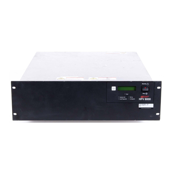
Page 97: Front Panel Drawing
HFV 8000 Generator Front Panel Drawing Figure 5-1. Front view 5705211-C Installation, Setup, and Operation... -
Page 98: Rear Panel Drawing
® Advanced Energy Rear Panel Drawing Rear access panel that houses the Host port connector and an 8-pin DIP switch Figure 5-2. Rear view (shown with optional water solenoid) Installation, Setup, and Operation 5705211-C... -
Page 99: Electromagnetic Field (Emf) Shielding Requirements
HFV 8000 Generator Electromagnetic Field (EMF) Shielding Requirements In order to meet current EMF compliance regulations, you must install the provided EMI suppression ferrite on the 15-pin, shielded Generator User port cable (see also “Generator User Port (15-Pin)” on page 4-1). -
Page 100: Connecting I/O And Auxiliary Connectors
® Advanced Energy To connect the cooling water, complete the following steps: 1. Connect the input and output water connections and tighten securely. 2. If you do not have an optional water solenoid, install the water shield. 3. Turn on the water and ensure that there are no leaks. -
Page 101: Connecting Output Power
HFV 8000 Generator Connecting Output Power Remove and lockout/tagout the input power before working on or around the output terminals. Failure to do so could result in death or bodily injury. Complete the following steps to connect the output power connector: 1. -
Page 102: First-Time Operation
® Advanced Energy This generator must be used in a pollution degree 2 or better environment. This device must be used in an overvoltage category II installation only. Make input power connections and wire terminations in accordance with local safety requirements. -
Page 103: Before Engaging The Rear Circuit Breaker
HFV 8000 Generator Before Engaging the Rear Circuit Breaker Become familiar with the Unpacking, Spacing Requirements, and Grounding sections in this chapter. Also, review the following sections: • Cooling water: “Connecting Cooling Water” on page 5-5. • Output power: “Connecting I/O and Auxiliary Connectors” on page 5-6. - Page 104 ® Advanced Energy 2. Turn the Standby/Stop switch on the front panel to the Standby (up) position. The generator should now be under control of the Generator User port or the DeviceNet interface. Note: If any problems arise during the preceding process, refer to the “Troubleshooting Guide”...
-
Page 105: Meeting Minimum Power Threshold
HFV 8000 Generator Meeting Minimum Power Threshold The output power set point minimum is a threshold that allows the generator to deliver power. The set point circuitry uses hysteresis so that the generator has two thresholds. If an RF On command is given, the power requested through the set point level must be above the minimum power On threshold for the HFV generator to deliver power. -
Page 106: Normal Operation
® Advanced Energy Top, Side, Full, or Custom [Bottom line] 2. If the bottom line of the display screen does not show the desired frequency band (that is, Top, Side, Full or Custom), then hold down the Display Mode button for approximately 5 seconds. -
Page 107: Automatic Tuning Mode
HFV 8000 Generator 1. Verify that the generator is set to the desired frequency band for your application (see “Setting the Frequency Band” on page 5-11). 2. Press the Display Mode button on the front panel repeatedly until the display reads: Top line—Press and Hold... -
Page 108: Adjusting Tuning Parameters
By characterizing a chamber, you can identify the scan threshold appropriate to a specific process and chamber. Advanced Energy offers HFV Virtual Front Panel (VFP) software that can help you characterize a chamber and identify appropriate tuning settings for it, then set those parameters (refer to the HFV VFP software manual for instructions). - Page 109 HFV 8000 Generator Frequency rate of change (ms) This value defines how quickly the generator moves through the steps during both the scanning and the tuning phases, in milliseconds. For example, if you set this value to 5, the generator will make tuning adjustments no more than every 5 ms. (See Table 4- 7, command 11, frequency rate of change.)
-
Page 110: Display Mode And The Lcd Display Indicator
® Advanced Energy Scan threshold The scan threshold sets a threshold below which the tuning phase begins. If the scan threshold is set too high, the generator will begin to tune too early and the tuning will not be optimal. If the scan threshold is set too low, the threshold may never be reached and automatic tuning will not take over. -
Page 111: Monitoring The Generator
HFV 8000 Generator • MODE 5 Top line—displays: Press and Hold Bottom line—displays: Mode for Diag MONITORING THE GENERATOR Table 5-2 describes the indicators on the HFV generator. Note: For information on DeviceNet indicators, see “DeviceNet™ Control Panel” on page 4-38. -
Page 112: Running Internal Diagnostics
® Advanced Energy Table 5-2. Indicators (Continued) Indicator Explanation At Set Point This green indicator illuminates whenever output power matches the requested power (within specified accuracy spec). If RF power is on, an unlit indicator indicates that an internal power limit has been reached. - Page 113 HFV 8000 Generator You can run the test only after configuring the generator in a special setup. Note: Regular generator control is disabled when diagnostics are in progress. An integrity report is visually indicated by the front panel LCD. To run the diagnostics: 1.
- Page 114 ® Advanced Energy 5-20 Installation, Setup, and Operation 5705211-C...
-
Page 115: Chapter 6. Troubleshooting And Global Customer Support
If yes, go to step 2. b. If no, see “Front Panel Display (LCD) Not Lit” on page 6-2. 2. Is “Advanced Energy Industries” displayed on the front panel LCD? a. If yes, see “Advanced Energy Displayed on LCD” on page 6-2. -
Page 116: Error Indications
2. Input line voltage is between 178 to 229 VAC between all three phases. Advanced Energy Displayed on LCD It is normal for ADVANCED ENERGY to display for a few seconds immediately after the rear circuit breaker has been enabled (this is not an internal fault mode indicator). -
Page 117: Fault Indicator On
HFV 8000 Generator Fault Indicator On This indicator latches on whenever the unit detects an overtemperature, RF On sequence error, or input line out of voltage range condition. If this fault occurs, the unit automatically shuts off the front panel LCD and displays the detected fault: Top line—*****FAULT*****... -
Page 118: Bad Cal Eeprom Fault
® Advanced Energy If these procedures do not help solve your problem, contact AE Global Customer Support (see “AE Global Customer Support” on page 6-10). BAD CAL EEPROM FAULT A fault of this type occurs when the calibration data stored on the measurement card’s EEPROM has been lost or corrupted. -
Page 119: Interlock Ok Indicator Off
HFV 8000 Generator 4 Cycle the power on the HFV generator. With the cable disconnected, the HFV generator will default to Generator User port control. Interlock OK Indicator Off The front panel Interlock OK indicator illuminates when the interlock is satisfied. If this indicator is not lit, the output will be disabled. -
Page 120: Rf On Indicator Off
® Advanced Energy Bottom line—Center/Auto Tune 2. Press and hold the Display Mode button for at least five seconds until the Load Regulation indicator flashes. To return to the automatic tuning mode: 1. Press the Display Mode button on the front panel repeatedly until the display reads: Top line—Press and Hold... -
Page 121: At Set Point Indicator Off
HFV 8000 Generator for the HFV generator to deliver power. The HFV generator will continue to deliver power until the set point level falls below the output off threshold, or until the RF on command is disabled (see command Table 4-7 on page 4-20). -
Page 122: No Output / No Plasma
® Advanced Energy For the output cable: a. Visually make sure there is a good connection between the output cable and end connectors on both sides of the output cable. b. Verify the continuity of the center conductor. c. Verify the continuity of the outer shield. -
Page 123: Ae World Wide Web Site
HFV 8000 Generator power). For more information, see the literature section on our web site at www.advanced-energy.com. Look for the document titled, “Forward and Reflected Powers. What do they really mean?” To verify that your reflected power is high, use the Display Mode button on the front panel to cycle through the display modes and monitor the reflected power reading. -
Page 124: Ae Global Customer Support
® Advanced Energy AE GLOBAL CUSTOMER SUPPORT Please contact one of the following offices if you have questions: Table 6-1. Global Customer Support locations Office Contact AE, World Headquarters Phone (24 hrs/day, 7 days/week): 800.446.9167 or 1625 Sharp Point Drive 970.221.0108... -
Page 125: Returning Units For Repair
Support and that unit is found to be functional, you will be charged a re-test and calibration fee plus shipping charges. ® To ensure years of dependable service, Advanced Energy products are thoroughly tested and designed to be among the most reliable and highest quality systems available worldwide. -
Page 126: Warranty
® Advanced Energy WARRANTY ® Advanced Energy (AE) products are warranted to be free from failures due to defects in material and workmanship for 12 months after they are shipped from the factory (please see warranty statement below, for details). -
Page 127: Warranty Statement
HFV 8000 Generator Warranty Statement The seller makes no express or implied warranty that the goods are merchantable or fit for any particular purpose except as specifically stated in printed AE specifications. The sole responsibility of the Seller shall be that it will manufacture the goods in accordance with its published specifications and that the goods will be free from defects in material and workmanship. - Page 128 ® Advanced Energy 6-14 Troubleshooting and Global Customer Support 5705211-C...
- Page 129 HFV 8000 Generator Glossary Automatic Tune mode This mode is the common mode of use that allows the operator to determine the output frequency range. See also “Automatic Tuning Mode” on page 5-13. To set the output frequency range using the Host port, see commands 3, 4, and 5 in...
- Page 130 ® Advanced Energy Frequency limits The frequency limits parameter sets the range of frequencies over which the HFV unit will operate. You can set a start frequency, an upper frequency limit, and a lower frequency limit. (See Table 4-7, commands 3, 4, and 5, minimum frequency, maximum frequency, and starting frequency.)
- Page 131 HFV 8000 Generator Tuning gain This parameter affects the size of the tuning steps; the larger the number, the greater the size of the tuning steps. (See Table 4-7, command 15, tuning gain.) Note: When setting the tuning gain, be aware that if the gain is set too low, the tuning function may react to noise in the signal and fail to correct the real direction of change.
- Page 132 ® Advanced Energy 5705211-C...
- Page 133 HFV 8000 Generator Index checksum 4-15 circuit breaker AC line sag response 3-7 rear 5-9 ACK, see acknowledgement circuitry 4-7 acknowledgement 4-16 see also illustrations addressing circuits DeviceNet 4-41 interlock 1-7 AE Bus 4-9 command 4-14 protocol 4-13 commands AE World Wide Web site 6-9...
- Page 134 HFV 8000 Generator 5705211-C...
- Page 135 ® Advanced Energy reset tuning parameters 4-21 DeviceNet 4-39 scan delta 4-22 controls scan threshold 4-22 front panel 5-4 set regulation mode 4-21 coolant starting frequency 4-21 connector/cable specifications 3-5 tuning delta limits 4-22 contaminates 3-9 tuning gain 4-22 flow rate 3-8...
- Page 136 EMC, see electromagnetic compatibility Host port environmental specifications 3-8 AE Bus protocol 4-13 error indications 6-2 baud rate 4-12 Advanced Energy displayed on LCD 6-2 commands 4-18 at set point indicator off 6-7 see also commands fault indicator on 6-3 communicating through 4-12...
- Page 137 ® Advanced Energy indicators selecting center frequency 5-12 at set point 5-18 mounting dimensions 3-4 error 6-2 see also error indications fault 5-18 NAK, see negative acknowledgement front panel 5-4 negative acknowledgement 4-16 interlock ok 5-17 normal operation 5-12 load regulation 5-17...
- Page 138 HFV 8000 Generator specification 3-6 see also pin descriptions regulation 3-6 4-21 analog 4-1 reporting, see commands digital 4-1 response time 3-6 User port pin descriptions 4-2 returning units for repair 6-11 size 3-4 RF on indicator 5-17 spacing requirements 5-1...
- Page 139 ® Advanced Energy scan delta frequency command 4-22 scan frequency delta 5-15 scan threshold 5-14 5-15 5-16 scan threshold command 4-22 starting frequency command 4-21 tuning delta limit command 4-22 tuning gain 5-15 tuning gain command 4-22 tuning goal 5-15...
- Page 140 HFV 8000 Generator 5705211-C viii...
- Page 141 ® Advanced Energy 5705211-C...
- Page 142 ® Advanced Energy Index-x 5705211-C...
Need help?
Do you have a question about the HFV 8000 and is the answer not in the manual?
Questions and answers