Advertisement
Quick Links
Advertisement

Related Manuals for Advanced Energy RFG 5500


Summary of Contents for Advanced Energy RFG 5500
- Page 1 THE ADVANCED ENERGY RFG 5500 GENERATOR WITH DISPLAY User Manual PN: 5706045-C December 2000...
- Page 2 ® ADVANCED ENERGY RFG 5500 GENERATOR WITH DISPLAY User Manual ADVANCED ENERGY INDUSTRIES, INC. 1625 Sharp Point Drive Fort Collins, Colorado 80525 (970) 221-4670 PN: 5706045-C December 2000...
- Page 3 Making copies of any part of this manual for any purpose without permission is a violation of U.S. copyright law. In the interest of providing even better equipment, Advanced Energy Industries, Inc., reserves the right to make product changes without notification or obligation.
- Page 4 EQUIPMENT ARE THE RESPONSIBILITY OF THE USER OF THIS SYSTEM. Advanced Energy Industries, Inc., provides information on its products and associated hazards, but it assumes no responsibility for the after-sale operation of the equipment or the safety practices of the owner or user.
- Page 6 RFG 5500 GENERATOR WITH DISPLAY Contents Introduction..........I-1 Read This Page .
- Page 7 ADVANCED ENERGY First-Time Operation........4-1 Troubleshooting ........5-1 Check First .
- Page 8 RFG 5500 GENERATOR WITH DISPLAY NTRODUCTION CONTENTS Read This Page ..........I-1 Overview of the Manual .
- Page 9 ADVANCED ENERGY Pin and signal names appear in capitalized italics (RF PWR ON CMD.D). Labels that are on the unit (switches, indicators, etc.) generally appear in boldface capital letters (MODIFY). Exceptions are port names, which simply begin with a capital letter (User port).
- Page 10 RFG 5500 GENERATOR WITH DISPLAY SAFETY Do not attempt to install or operate this equipment without having proper training first. Make sure this unit is properly grounded. (Protective ground is accomplished through the green/yellow ground wire in the ac power cord. RF (EMI) grounding is accomplished by using a copper strap between earth ground and the ground stud on the unit’s chassis...
- Page 11 ADVANCED ENERGY December 2000 P/N 5706045C...
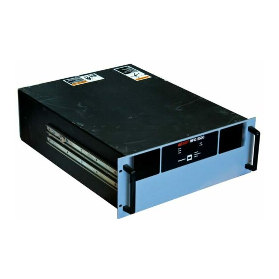
- Page 12 The RFG 5500 provides up to 5000 W into a 50 Ω, non-reactive load. The RFG 5500 includes a clamp circuit to guarantee that the RF output is less than 1 W if the requested setpoint is zero.
- Page 13 ADVANCED ENERGY PHYSICAL SPECIFICATIONS Size 17.8 cm (H) x 48.3 cm (W) x 58.4 cm (D) (7” (H) x 19” (W) x 23” (D)) Weight 52.2 Kg (115 pounds) maximum Mounting Rack mounting ears provided for standard 19” instrumentation rack. Side handles are provided to assist in lifting.
- Page 14 < 0.5% over time for same generator, ± 1% generator Command Power Repeatability to generator Demonstrated Open Loop Power 10 kW into a 50 Ω load Power Margin 100% RFG 5500 (5kW S caling) Power Derating 5000 Forward Power 4000 Reflected Power 3000...
- Page 15 100 psi (6.9 bars) maximum inlet pressure Contaminates The following specifications are recommended for the water used to cool the RFG 5500: • pH between 7 and 9 • total chlorine < 20 ppm • total nitrate < 10 ppm •...
- Page 16 RFG 5500 GENERATOR WITH DISPLAY ONNECTORS, CONTROLS, AND INDICATORS CONTENTS Interface Configurations......... . . 2-1 Operator Panel Functions .
- Page 17 Reserved Reserved for future use User Port Electrical Characteristics The User port on the RFG 5500 provides analog and digital signals for control and monitoring of the generator functions. Figure 2-2 shows the electrical diagrams for December 2000 P/N 5706045C...
- Page 18 RFG 5500 GENERATOR WITH DISPLAY the interface circuitry in the generator. The following are descriptions of the signal types used in the RFG 5500 . Analog Outputs The analog readback signals from the generator ) are driven by precision, low-offset pins 2 operational amplifiers (industry type OP200GP).
- Page 19 ADVANCED ENERGY FIGURE 2-2 User Port Electrical Diagrams December 2000 P/N 5706045C...
- Page 20 Watts This LED indicates that the value being displayed is in watts. For the RFG 5500, this indicator is always lit. X 1000 This LED indicates that the value being displayed has been scaled and must be multiplied by 1000. For the RFG 5500, this indicator is always lit.
- Page 21 ADVANCED ENERGY Front Panel FIGURE 2-3 Front panel December 2000 P/N 5706045C...
- Page 22 RFG 5500 GENERATOR WITH DISPLAY Rear Panel FIGURE 2-4 Rear panel P/N 5706045C December 2000...
- Page 23 ADVANCED ENERGY December 2000 P/N 5706045C...
-
Page 24: Table Of Contents
Grounding The RFG 5500 provides an RF (EMI) ground stud. It is recommended that a suitable ground connection be made to this stud to prevent or minimize radio frequency interference. NOTE: We recommend copper strap material 0.5”... - Page 25 ADVANCED ENERGY FIGURE 3-1 Mounting hole locations and dimensions December 2000 P/N 5706045C...
-
Page 26: Connecting Cooling Water
Make sure the mating connector is completely engaged and fully tightened before proceeding. Output Power Cable Recommendations The recommended RF cable for the RFG 5500 is type RG 393 because of its high insulative values, small size, and high reliability. P/N 5706045C... -
Page 27: Connecting User Port
To minimize interference from adjacent electrical equipment, the EMI shield in the cable must be terminated to the metal shells of the cable’s D connectors. Additionally, the chassis of the RFG 5500 must be tied to a local earth ground through an adequately sized copper grounding strap. - Page 28 • De-activate the generator’s interlock loop by leaving pin 11 unconnected. • Move the circuit breaker on the rear of the RFG 5500 to the on (“1”) position. The display on the front of the generator illuminates and the Setpoint, Watts, and X1000 indicators are lit.
- Page 29 ADVANCED ENERGY • Continue to increase the setpoint until the display indicates approximately 200 W of Note: power. The display is scaled by a factor of 1000, (200 W is displayed as “.20”). • Use the DISPLAY SELECT push button to display the setpoint value. The forward power and setpoint values should agree with each other within the allowable regula- tion tolerance of the generator (1%).
- Page 30 RFG 5500 GENERATOR WITH DISPLAY ROUBLESHOOTING CONTENTS Check First ..........5-1 Troubleshooting Flowchart .
- Page 31 ADVANCED ENERGY START Is the "AC ON" LED lit? Unit could have experienced an overtemperature condition Is the generator’s interlock loop due to high water temperature being satisfied? Confirm that pin or low flow while the system 11 on the unit’s interface is was sitting at idle.
- Page 32 RFG 5500 GENERATOR WITH DISPLAY Is the "RF ON" LED lit? When the AC circuit Once the problem breaker is cycled, is the has been identified Is the Alarm alarm LED lit? (The unit and corrected, you LED lit? may have been in a can resume your overtemp condition.)
- Page 33 ADVANCED ENERGY If a different problem Does the unit exists other than what meet calibration was covered, please specs at contact your nearest setpoint? AE customer service. Unit is "OK". Check Is there high system, coaxial cable, Place the circuit...
- Page 34 To ensure years of dependable service, Advanced Energy® products are thoroughly tested and designed to be among the most reliable and highest quality systems available worldwide. All parts and labor carry our standard 18-month warranty.
- Page 35 ADVANCED ENERGY Advanced Energy Industries, GmbH Phone: 49-711-77927-0 Raiffeisensstrasse 32 Fax: 49-711-7778700 70794 Filderstadt (Bonlanden) Germany Advanced Energy Industries, Japan KK Phone: 81-3-32351511 TOWA Edogawabashi Fax: 81-3-32353580 Building 347 Yamabuki-cho Shinjuku-ku, Tokyo, Japan Advanced Energy Industries, United Kingdom Phone: 44-1869-321622...
- Page 36 Warranty Claims Advanced Energy products are warranted to be free from failures due to defects in material and workmanship for 18 months after they are shipped from the factory (please see warranty statement, below, for details). In order to claim shipping or handling damage, you must inspect the delivered goods and report such damage to AE within 30 days of your receipt of the goods.
- Page 37 ndex AC Power Input 1-2 Mounting 1-2, 3-1 Ambient Temperature 1-4 Mounting hole locations and dimensions 3-2 Analog Input 2-3 Analog Outputs 2-3 Atmospheric Pressure 1-4 Operating 1-4 OPERATION 4-1 OPERATOR PANEL FUNCTIONS 2-5 Check First 5-1 OTHER TECHNICAL PROBLEMS 5-5 Circuit Breaker Lockout 1-2 Output Impedance 1-2 Clearance 1-2...
Need help?
Do you have a question about the RFG 5500 and is the answer not in the manual?
Questions and answers