WAGO I/O-SYSTEM 750 Manual
Ethercat fieldbus coupler, id switch 100 mbit/s; digital and analog signals
Hide thumbs
Also See for I/O-SYSTEM 750:
- User manual ,
- Manual (450 pages) ,
- User's installation and configuration (335 pages)

Related Manuals for WAGO I/O-SYSTEM 750


Summary of Contents for WAGO I/O-SYSTEM 750
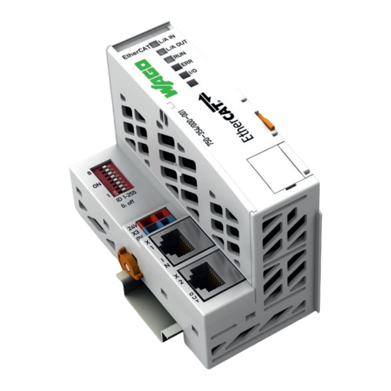
- Page 1 Manual WAGO-I/O-SYSTEM 750 750-354/000-001 ® EtherCAT Fieldbus Coupler, ID Switch 100 Mbit/s; digital and analog signals Version 1.2.1...
- Page 2 We wish to point out that the software and hardware terms as well as the trademarks of companies used and/or mentioned in the present manual are generally protected by trademark or patent. WAGO is a registered trademark of WAGO Verwaltungsgesellschaft mbH. Manual Version 1.2.1...
-
Page 3: Table Of Contents
Framework Assembly ..............37 3.6.1.2 Insulated Assembly ..............37 3.6.2 Grounding Function ................38 Shielding ....................39 3.7.1 General ..................... 39 3.7.2 Bus Cables ..................39 3.7.3 Shielded Signal Lines ................ 40 3.7.4 WAGO Shield Connecting System ............ 40 Manual Version 1.2.1... - Page 4 Overall Configuration ................54 Mounting onto Carrier Rail ..............56 5.3.1 Carrier Rail Properties ............... 56 5.3.2 WAGO DIN Rails ................57 Spacing ....................57 Mounting Sequence ................58 Inserting and Removing Devices ............59 5.6.1 Inserting the Fieldbus Coupler/Controller .......... 60 5.6.2...
-
Page 5: Table Of Contents
Connecting Client PC and Fieldbus Nodes .......... 118 Load XML-File in the Master ..............118 Testing the Function of the EtherCAT Fieldbus Node ......119 Testing I/O Modules using WAGO-I/O-CHECK ........120 Diagnostics ..................... 121 Fieldbus Coupler Diagnostics .............. 121 9.1.1 LED Signaling ................. 121 9.1.2... - Page 6 Table of Contents WAGO-I/O-SYSTEM 750 750-354/000-001 EtherCAT® Fieldbus Coupler, ID Switch 10.1.2.2 Network Topology ............... 141 10.1.2.3 Couplers ..................142 10.1.3 Network Communication ..............142 10.1.3.1 Communication Principle ............142 10.1.3.2 Addressing .................. 142 10.1.3.3 Configuration ................143 10.1.3.4 EtherCAT State Machine (ESM) ..........
-
Page 7: Table Of Contents
WAGO-I/O-SYSTEM 750 Table of Contents 750-354/000-001 EtherCAT® Fieldbus Coupler, ID Switch 11.2.5 Specialty Modules ................170 11.2.5.1 Counter Modules ................ 171 11.2.5.2 Pulse Width Modules ..............173 11.2.5.3 Serial Interface Modules with Alternative Data Format ....173 11.2.5.4 Serial Interface Modules with Standard Data Format ....174 11.2.5.5... -
Page 8: Notes About This Documentation
Consider power layout of the WAGO-I/O-SYSTEM 750! In addition to these operating instructions, you will also need the system description for the WAGO-I/O-SYSTEM 750, which can be downloaded at www.wago.com. There, you can obtain important information including information on electrical isolation, system power and supply specifications. -
Page 9: Symbols
WAGO-I/O-SYSTEM 750 Notes about this Documentation 750-354/000-001 EtherCAT® Fieldbus Coupler, ID Switch Symbols Personal Injury! Indicates a high-risk, imminently hazardous situation which, if not avoided, will result in death or serious injury. Personal Injury Caused by Electric Current! Indicates a high-risk, imminently hazardous situation which, if not avoided, will result in death or serious injury. - Page 10 Notes about this Documentation WAGO-I/O-SYSTEM 750 750-354/000-001 EtherCAT® Fieldbus Coupler, ID Switch Additional Information: Refers to additional information which is not an integral part of this documentation (e.g., the Internet). Manual Version 1.2.1...
-
Page 11: Number Notation
Font Conventions Table 2: Font Conventions Font Type Indicates italic Names of paths and data files are marked in italic-type. e.g.: C:\Program Files\WAGO Software Menu Menu items are marked in bold letters. e.g.: Save > A greater-than sign between two names means the selection of a menu item from a menu. -
Page 12: Important Notes
2.1.1 Subject to Changes WAGO Kontakttechnik GmbH & Co. KG reserves the right to provide for any alterations or modifications. WAGO Kontakttechnik GmbH & Co. KG owns all rights arising from the granting of patents or from the legal protection of utility patents. -
Page 13: Technical Condition Of Specified Devices
These modules contain no parts that can be serviced or repaired by the user. The following actions will result in the exclusion of liability on the part of WAGO Kontakttechnik GmbH & Co. KG: •... -
Page 14: 2.1.4.1.2 Packaging
Important Notes WAGO-I/O-SYSTEM 750 750-354/000-001 EtherCAT® Fieldbus Coupler, ID Switch Environmentally friendly disposal benefits health and protects the environment from harmful substances in electrical and electronic equipment. • Observe national and local regulations for the disposal of electrical and electronic equipment. -
Page 15: Safety Advice (Precautions)
Install the device only in appropriate housings, cabinets or in electrical operation rooms! The WAGO-I/O-SYSTEM 750 and its components are an open system. As such, install the system and its components exclusively in appropriate housings, cabinets or in electrical operation rooms. Allow access to such equipment and fixtures to authorized, qualified staff only by means of specific keys or tools. - Page 16 Important Notes WAGO-I/O-SYSTEM 750 750-354/000-001 EtherCAT® Fieldbus Coupler, ID Switch Clean only with permitted materials! Clean housing and soiled contacts with propanol. Do not use any contact spray! Do not use any contact spray. The spray may impair contact area functionality in connection with contamination.
-
Page 17: Special Use Conditions For Ethernet Devices
• Do not connect control components and control networks to an open network such as the Internet or an office network. WAGO recommends putting control components and control networks behind a firewall. • Limit physical and electronic access to all automation components to authorized personnel only. -
Page 18: System Description
The communication between the fieldbus coupler/controller and the I/O modules is carried out via a local bus. The components of the WAGO-I/O-SYSTEM 750 have clear termination points, light emitting diodes for status display, plug-in mini WSB tags and group marker cards for labeling. -
Page 19: Manufacturing Number
WAGO-I/O-SYSTEM 750 System Description 750-354/000-001 EtherCAT® Fieldbus Coupler, ID Switch Manufacturing Number The serial number indicates the delivery status directly after production. This number is part of the labeling on the side of each component. Figure 2: Marking Area for Serial Numbers There are two serial numbers in two rows in the side marking. -
Page 20: Update
System Description WAGO-I/O-SYSTEM 750 750-354/000-001 EtherCAT® Fieldbus Coupler, ID Switch Update For products that can be updated, the side inscription has a prepared matrix in which the current update data can be entered in columns. Up to 2015, the matrix has rows to enter the “NO” work order number (or “BA” to CW 13/2004), “DS”... -
Page 21: Storage, Assembly And Transport
WAGO-I/O-SYSTEM 750 System Description 750-354/000-001 EtherCAT® Fieldbus Coupler, ID Switch Storage, Assembly and Transport Whenever possible, the components are to be stored in their original packaging. Likewise, the original packaging provides optimal protection during transport. When assembling or repacking the components, the contacts must not be soiled or damaged. -
Page 22: Assembly Guidelines/Standards
System Description WAGO-I/O-SYSTEM 750 750-354/000-001 EtherCAT® Fieldbus Coupler, ID Switch Assembly Guidelines/Standards • DIN 60204 Electrical equipment of machines • DIN EN 50178 Electronic equipment for use in power installations (replacement for VDE 0160) • EN 60439 Low-voltage switchgear and controlgear assemblies Manual Version 1.2.1... -
Page 23: Power Supply
750-354/000-001 EtherCAT® Fieldbus Coupler, ID Switch Power Supply 3.5.1 Overcurrent Protection The system and field voltage of the WAGO-I/O-SYSTEMs 750 is supplied on the head stations and bus supply modules. For components that work with extra low voltage, only SELV/PELV voltage sources should be used. -
Page 24: System Supply
System Supply 3.5.3.1 Connection The WAGO-I/O-SYSTEM 750 requires a 24 V direct current system supply. The power supply is provided via the fieldbus coupler/controller and, if necessary, in addition via internal system supply modules 750-613. The power supply is reverse voltage protected. -
Page 25: Dimensioning
WAGO-I/O-SYSTEM 750 System Description 750-354/000-001 EtherCAT® Fieldbus Coupler, ID Switch System supply only with appropriate fuse protection! Without overcurrent protection, the electronics can be damaged. If you implement the overcurrent protection for the system supply with a fuse, a fuse, max. 2 A, slow-acting, should be used. -
Page 26: Table 5: Alignment
System Description WAGO-I/O-SYSTEM 750 750-354/000-001 EtherCAT® Fieldbus Coupler, ID Switch Table 5: Alignment Internal current consumption Current consumption via system voltage (5 V for electronics of I/O modules and fieldbus coupler/controller). Total current for I/O modules Available current for the I/O modules. - Page 27 Consequently, an internal system supply module (750-613), e. g. in the middle of the node, should be added. Recommendation ® Utilize the smartDESIGNER feature WAGO ProServe software to configure fieldbus node assembly. You can test the configuration via the integrated plausibility check.
-
Page 28: Field Supply
System Description WAGO-I/O-SYSTEM 750 750-354/000-001 EtherCAT® Fieldbus Coupler, ID Switch Fieldbus coupler or controller = Sum of all the internal current consumption of the (5 V) total connected I/O modules + internal current consumption of the fieldbus coupler/controller Internal system supply module... -
Page 29: Figure 8: Field Supply (Sensor/Actuator)
WAGO-I/O-SYSTEM 750 System Description 750-354/000-001 EtherCAT® Fieldbus Coupler, ID Switch Figure 8: Field Supply (Sensor/Actuator) Table 6: Legend for Figure “Field Supply (Sensor/Actuator) for ECO Fieldbus Coupler” Field supply 24 V (-15 % / +20 %) Optional ground potential (functional earth) -
Page 30: Fusing Via Power Supply Module
System Description WAGO-I/O-SYSTEM 750 750-354/000-001 EtherCAT® Fieldbus Coupler, ID Switch Re-establish the ground connection when the connection to the power jumper contacts is disrupted! Some I/O modules have no or very few power contacts (depending on the I/O function). Due to this, the passing through of the relevant potential is disrupted. If you require a field supply via power jumper contacts for subsequent I/O modules, then you have to use a power supply module. -
Page 31: Figure 9: Supply Module With Fuse Carrier (Example 750-610)
WAGO-I/O-SYSTEM 750 System Description 750-354/000-001 EtherCAT® Fieldbus Coupler, ID Switch Figure 9: Supply Module with Fuse Carrier (Example 750-610) Observe the maximum power dissipation and, if required, UL requirements! In the case of power supply modules with fuse holders, you must only use fuses with a maximum dissipation of 1.6 W (IEC 127). -
Page 32: Fusing External
If you alternatively implement the overcurrent protection for the field supply with an external fuse, an F 10 A fuse should be used. For the external fusing, the fuse modules of the WAGO series 282, 2006, 281 and 2002 are suitable for this purpose. -
Page 33: Figure 14: Fuse Modules For Automotive Fuses, Series 2006
WAGO-I/O-SYSTEM 750 System Description 750-354/000-001 EtherCAT® Fieldbus Coupler, ID Switch Figure 14: Fuse Modules for Automotive Fuses, Series 2006 Figure 15: Fuse Modules with Pivotable Fuse Carrier, Series 281 Figure 16: Fuse Modules with Pivotable Fuse Carrier, Series 2002 Manual... -
Page 34: Supply Example
System Description WAGO-I/O-SYSTEM 750 750-354/000-001 EtherCAT® Fieldbus Coupler, ID Switch 3.5.5 Supply Example SupplSggggggggggggggggg The system supply and the field supply shall be separated! You should separate the system supply and the field supply in order to ensure bus operation in the event of a short-circuit on the actuator side. -
Page 35: Table 8: Legend For Figure "Supply Example For Fieldbus Coupler/Controller
WAGO-I/O-SYSTEM 750 System Description 750-354/000-001 EtherCAT® Fieldbus Coupler, ID Switch Table 8: Legend for Figure “Supply Example for Fieldbus Coupler/Controller” Pos. Description Power Supply on fieldbus coupler/controller via external Supply Module Power Supply with optional ground Internal System Supply Module... -
Page 36: Power Supply Unit
750-354/000-001 EtherCAT® Fieldbus Coupler, ID Switch 3.5.6 Power Supply Unit The WAGO-I/O-SYSTEM 750 requires a 24 VDC voltage (system supply). Recommendation A stable power supply cannot always be assumed everywhere. Therefore, you should use regulated power supplies to ensure the quality of the supply voltage. -
Page 37: Grounding
The optimal setup is a metallic assembly plate with grounding connection which is electrically conductive linked to the carrier rail. The separate grounding of the carrier rail can be easily set up with the aid of the WAGO ground wire terminals. Table 9: WAGO Ground Wire Terminals Order No. Description 283-609 1-conductor ground (earth) terminal block make an automatic contact to the carrier rail;... -
Page 38: Grounding Function
System Description WAGO-I/O-SYSTEM 750 750-354/000-001 EtherCAT® Fieldbus Coupler, ID Switch 3.6.2 Grounding Function The grounding function increases the resistance against electro-magnetic interferences. Some components in the I/O system have a carrier rail contact that dissipates electro-magnetic interferences to the carrier rail. -
Page 39: Shielding
Higher shielding performance is achieved via low-impedance connection between shield and ground. For this purpose, connect the shield over a large surface area, e.g., WAGO shield connecting system. This is especially recommended for large-scale systems where equalizing current or high impulse- type currents caused by atmospheric discharge may occur. -
Page 40: Shielded Signal Lines
I/O module can be achieved even in the presence of interference acting on the signal cable. On some WAGO devices you can directly clamp the shield. For all other devices use the WAGO shield connecting system. -
Page 41: Device Description
WAGO-I/O-SYSTEM 750 Device Description 750-354/000-001 EtherCAT® Fieldbus Coupler, ID Switch Device Description The Fieldbus coupler 750-354/000-001 connects the WAGO-I/O-SYSTEM with the Fieldbus system EtherCAT This coupler can be used for applications in machine and plant construction as well as in the process industry and building technology. -
Page 42: View
Device Description WAGO-I/O-SYSTEM 750 750-354/000-001 EtherCAT® Fieldbus Coupler, ID Switch View The view below shows the different parts of the device: • The fieldbus connection (X1, X2) is within the lower range on the left side. • Over the fieldbus connection is a power supply unit (X3) for the system supply. -
Page 43: Table 10: Legend For Figure "View Ethercat Fieldbus Coupler
WAGO-I/O-SYSTEM 750 Device Description 750-354/000-001 EtherCAT® Fieldbus Coupler, ID Switch Table 10: Legend for Figure “View EtherCAT Fieldbus Coupler” Desig- Pos. Meaning Details see Section nation L/A IN, L/A OUT, „Device Description“ > Status LEDs Fieldbus RUN, „Display Elements“... -
Page 44: Connectors
Device Description WAGO-I/O-SYSTEM 750 750-354/000-001 EtherCAT® Fieldbus Coupler, ID Switch Connectors 4.2.1 Device Supply ® The device is powered via terminal blocks with CAGE CLAMP connections. The device supply generates the necessary voltage to power the electronics of the device and the internal electronics of the connected I/O modules. -
Page 45: Figure 24: Rj-45 Connector
WAGO-I/O-SYSTEM 750 Device Description 750-354/000-001 EtherCAT® Fieldbus Coupler, ID Switch Figure 24: RJ-45 Connector Table 11: RJ-45 Connector and RJ-45 Connector Configuration Contact Signal TD + Transmit + TD − Transmit − RD + Receive + free free RD −... -
Page 46: Display Elements
Device Description WAGO-I/O-SYSTEM 750 750-354/000-001 EtherCAT® Fieldbus Coupler, ID Switch Display Elements The operating condition of the fieldbus coupler or the node is displayed with the help of illuminated indicators in the form of light-emitting diodes (LEDs). The LED information is routed to the top of the case by light guides. In some cases, the LEDs are multi-colored (red, green or orange). -
Page 47: Operating Elements
The connection to the 4-pin header under the cover flap can be realized via the communication cables with the item numbers750-920 and 750-923 or via the WAGO radio adapter with the item number 750-921. Alternatively, the connection can be made using either a USB cable (WAGO USB ® Service Cable 750-923) or a Bluetooth dongle (WAGO Radio Adapter 750-921). -
Page 48: Id Selection Switch
The upper eight bits (bit 8 to bit 15) of the “Explicit Device ID” can be configured via the SDO object 0x2134 and then stored in the device. Together, the two ® values form the fixed “Explicit Device ID” value of the WAGO EtherCAT slave. Table 15: EDI Address Structure (“Explicit Device ID”) Bit 15 ...8... -
Page 49: Technical Data
WAGO-I/O-SYSTEM 750 Device Description 750-354/000-001 EtherCAT® Fieldbus Coupler, ID Switch Technical Data 4.5.1 Device Data Table 16: Technical Data – Device Data Width 50 mm Height 65 mm (from upper-edge of DIN 35 rail) Length 97 mm Weight 100 g Material Polycarbonate, Polyamide 6.6... -
Page 50: Communication
Device Description WAGO-I/O-SYSTEM 750 750-354/000-001 EtherCAT® Fieldbus Coupler, ID Switch 4.5.4 Communication Table 19: Technical Data – Communication Number of Fieldbus nodes per Master Limited by ETHERNET specification Transmission medium Shielded twisted pair S/FTP, F/FTP or SF/FTP; 100 Ω, Cat 6 Buscoupler connection 2 ×... -
Page 51: Climatic Environmental Conditions
WAGO-I/O-SYSTEM 750 Device Description 750-354/000-001 EtherCAT® Fieldbus Coupler, ID Switch 4.5.7 Climatic Environmental Conditions Table 24: Technical Data – Climatic Environmental Conditions Surrounding air temperature, operation 0 °C … 55 °C Surrounding air temperature, storage −25 °C … +85 °C... -
Page 52: Approvals
Approvals More information about approvals. Detailed references to the approvals are listed in the document “Overview Approvals WAGO-I/O-SYSTEM 750”, which you can find via the internet under: www.wago.com > SERVICES > DOWNLOADS > Additional documentation and information on automation products > WAGO-I/O-SYSTEM 750 > System Description. -
Page 53: Standards And Guidelines
WAGO-I/O-SYSTEM 750 Device Description 750-354/000-001 EtherCAT® Fieldbus Coupler, ID Switch Standards and Guidelines 750-354/000-001 meets the following requirements on emission and immunity of interference: EMC CE-Immunity to interference EN 61000-6-2 and to EN 61131-2 EMC CE-Emission of interference EN 61000-6-3... -
Page 54: Mounting
Use an end stop in the case of vertical mounting! In the case of vertical assembly, an end stop has to be mounted as an additional safeguard against slipping. WAGO order no. 249-116 End stop for DIN 35 rail, 6 mm wide WAGO order no. 249-117... - Page 55 WAGO-I/O-SYSTEM 750 Mounting 750-354/000-001 EtherCAT® Fieldbus Coupler, ID Switch Increase the total length using a coupler module for internal data bus extension! You can increase the total length of a fieldbus node by using a 750-628 I/O Module (coupler module for internal data bus extension). For such a configuration, attach a 750-627 I/O Module (end module for internal data bus extension) after the last I/O module of a module assembly.
-
Page 56: Mounting Onto Carrier Rail
WAGO Kontakttechnik GmbH & Co. KG supplies standardized carrier rails that are optimal for use with the I/O system. If other carrier rails are used, then a technical inspection and approval of the rail by WAGO Kontakttechnik GmbH & Co. KG should take place. -
Page 57: Wago Din Rails
WAGO-I/O-SYSTEM 750 Mounting 750-354/000-001 EtherCAT® Fieldbus Coupler, ID Switch 5.3.2 WAGO DIN Rails WAGO carrier rails meet the electrical and mechanical requirements shown in the table below. Table 26: WAGO DIN Rails Item No. Description 210-112 35 × 7.5; 1 mm; steel; bluish, tinned, chromed; slotted 210-113 35 ×... -
Page 58: Mounting Sequence
Don't forget the bus end module! Always plug a bus end module (750-600) onto the end of the fieldbus node! You must always use a bus end module at all fieldbus nodes with WAGO-I/O- SYSTEM 750 fieldbus couplers or controllers to guarantee proper data transfer. -
Page 59: Inserting And Removing Devices
WAGO-I/O-SYSTEM 750 Mounting 750-354/000-001 EtherCAT® Fieldbus Coupler, ID Switch Inserting and Removing Devices Do not work when devices are energized! High voltage can cause electric shock or burns. Switch off all power to the device prior to performing any installation, repair or maintenance work. -
Page 60: Inserting The Fieldbus Coupler/Controller
Mounting WAGO-I/O-SYSTEM 750 750-354/000-001 EtherCAT® Fieldbus Coupler, ID Switch 5.6.1 Inserting the Fieldbus Coupler/Controller When replacing the fieldbus coupler/controller for an already available fieldbus coupler/controller, position the new fieldbus coupler/controller so that the tongue and groove joints to the subsequent I/O module are engaged. -
Page 61: Inserting The I/O Module
WAGO-I/O-SYSTEM 750 Mounting 750-354/000-001 EtherCAT® Fieldbus Coupler, ID Switch 5.6.3 Inserting the I/O Module Position the I/O module so that the tongue and groove joints to the fieldbus coupler or controller or to the previous or possibly subsequent I/O module engaged. -
Page 62: Removing The I/O Module
Mounting WAGO-I/O-SYSTEM 750 750-354/000-001 EtherCAT® Fieldbus Coupler, ID Switch 5.6.4 Removing the I/O Module Remove the I/O module from the assembly by pulling the release tab. Figure 32: Removing the I/O Module (Example) Electrical connections for data or power jumper contacts are disconnected when removing the I/O module. -
Page 63: Connect Devices
WAGO-I/O-SYSTEM 750 Connect Devices 750-354/000-001 EtherCAT® Fieldbus Coupler, ID Switch Connect Devices Data Contacts/Local Bus Communication between the fieldbus coupler/controller and the I/O modules as well as the system supply of the I/O modules is carried out via the local bus. It is comprised of 6 data contacts, which are available as self-cleaning gold spring contacts. -
Page 64: Power Contacts/Field Supply
Figure 34: Example for the Arrangement of Power Contacts Field bus node configuration and test via smartDESIGNER ® With the WAGO ProServe Software smartDESIGNER, you can configure the structure of a fieldbus node. You can test the configuration via the integrated accuracy check. -
Page 65: Connecting A Conductor To The Cage Clamp
Only one conductor may be connected to each CAGE CLAMP Do not connect more than one conductor at one single connection! If more than one conductor must be routed to one connection, these must be connected in an up-circuit wiring assembly, for example using WAGO feed- through terminals. ®... -
Page 66: Function Description
Function Description WAGO-I/O-SYSTEM 750 750-354/000-001 EtherCAT® Fieldbus Coupler, ID Switch Function Description Starting Up the Fieldbus Coupler Once the master switch has been configured and the fieldbus coupler and the I/O modules have been electrically installed, the fieldbus node starts running. -
Page 67: Start Behavior
WAGO-I/O-SYSTEM 750 Function Description 750-354/000-001 EtherCAT® Fieldbus Coupler, ID Switch More information about the LED Signaling Read the detailed description for the evaluation of the displayed LED state in the section “Diagnostics” > … > “LED Signaling”. Start Behavior ®... -
Page 68: Process Data Architecture
Function Description WAGO-I/O-SYSTEM 750 750-354/000-001 EtherCAT® Fieldbus Coupler, ID Switch Figure 36: Start Behavior Process Data Architecture After switching on the supply voltage, the fieldbus coupler identifies all I/O modules connected with the node that send or receive data (data width/bit width >... -
Page 69: General Mechanisms For Ethercat To Map Process Data
For some I/O modules and their different versions, the structure of the process data depends on the fieldbus. Additional information about the fieldbus specific process image For the fieldbus-specific process image of any WAGO-I/O-Module, please refer to the section “Structure of the Process Data”. ... -
Page 70: Figure 37: Mapping The Process Data
Function Description WAGO-I/O-SYSTEM 750 750-354/000-001 EtherCAT® Fieldbus Coupler, ID Switch Figure 37: Mapping the Process Data The process data are saved in the slave RAM and are represented in the input area (0x6000..0x6FFF) and output area (0x7000..0x7FFF) in the Object Dictionary in the slave by corresponding objects. -
Page 71: Figure 38: Example Of The Principle Mapping Of Process Data Using
WAGO-I/O-SYSTEM 750 Function Description 750-354/000-001 EtherCAT® Fieldbus Coupler, ID Switch Figure 38: Example of the Principle Mapping of Process Data Using EtherCAT Mapping of the process data takes place using the fieldbus coupler according to the modular device profile. A special sub-profile of the modular device profile is not implemented. -
Page 72: Object 0X6000
Function Description WAGO-I/O-SYSTEM 750 750-354/000-001 EtherCAT® Fieldbus Coupler, ID Switch • the control data for the fieldbus coupler are in object 0xF200 Additional Information about the Data Structure The structure of the cyclically exchanged data is identical with the internal structure of the process image. -
Page 73: Object 0X7000
WAGO-I/O-SYSTEM 750 Function Description 750-354/000-001 EtherCAT® Fieldbus Coupler, ID Switch Examples Table 28: Example Structure for Object 0x6000 for 750-433 – 4 DI Sub-Index Data Type Number of bits Description UINT8 Number of Entries BOOLEAN Channel 1 Data BOOLEAN Channel 2 Data... -
Page 74: Table 30: Generic Structure Of Object 0X7000
Function Description WAGO-I/O-SYSTEM 750 750-354/000-001 EtherCAT® Fieldbus Coupler, ID Switch Table 30: Generic Structure of Object 0x7000 Sub-Index Data Type Number of bits Description UINT8 Number of Entries Depends on IOM: Depends on IOM: Depends on IOM: BOOLEAN Channel x Status... -
Page 75: Object 0Xf100
WAGO-I/O-SYSTEM 750 Function Description 750-354/000-001 EtherCAT® Fieldbus Coupler, ID Switch 7.3.1.3 Object 0xF100 Object 0xF100 contains the status data of the fieldbus coupler according to the modular device profile. In addition, it contains the diagnostic messages for the I/O modules. -
Page 76: Rxpdo And Txpdo Objects
Function Description WAGO-I/O-SYSTEM 750 750-354/000-001 EtherCAT® Fieldbus Coupler, ID Switch 7.3.1.5 RxPDO and TxPDO Objects Both an RxPDO and a TxPDO are reserved for each I/O module. The indices for the RxPDO's are assigned to the I/O modules by the modular... -
Page 77: Alternative Pdo Index Assignment
WAGO-I/O-SYSTEM 750 Function Description 750-354/000-001 EtherCAT® Fieldbus Coupler, ID Switch Sync Manager Assignment Lists The Sync Manager Assignment Lists 0x1C12 and 0x1C13 contain a list of all Rx and TxPDO's that are cyclically transmitted. The order of the indices determines the order in which the data referenced by the PDO's is transmitted. -
Page 78: Example According To The Modular Device Profile
Function Description WAGO-I/O-SYSTEM 750 750-354/000-001 EtherCAT® Fieldbus Coupler, ID Switch For XML files with fieldbus coupler and I/O module descriptions, indexing according to the modular device profile! When using the XML file that contains descriptions for fieldbus couplers and I/O modules for the configuration, always use indexing according to the module device profile (0x2100:02 = FALSE). -
Page 79: Table 37: Example Output Process Image
WAGO-I/O-SYSTEM 750 Function Description 750-354/000-001 EtherCAT® Fieldbus Coupler, ID Switch Process Images Using this exemplary fieldbus node structure results in the following output and input process image represented in the fieldbus coupler. Table 37: Example Output Process Image Word Offset... -
Page 80: Table 39: Object 0Xf100 (Fieldbus Coupler Status Information)
Function Description WAGO-I/O-SYSTEM 750 750-354/000-001 EtherCAT® Fieldbus Coupler, ID Switch Fieldbus Coupler Objects The objects specified in the following are applied for the fieldbus coupler. Table 39: Object 0xF100 (Fieldbus Coupler Status Information) Subindex Data Type Number of Bits Description... -
Page 81: Table 42: Object 0X1Aff (Fieldbus Coupler Status Pdo)
WAGO-I/O-SYSTEM 750 Function Description 750-354/000-001 EtherCAT® Fieldbus Coupler, ID Switch Table 42: Object 0x1AFF (Fieldbus Coupler Status PDO) Subindex Data Type Description Value UINT8 Number of Entries UINT32 Coupler Status, K-Bus Cycle Overrun 0xF100.01.01 Flag UINT32 Coupler Status, Input Process Data 0xF100.02.01... -
Page 82: Table 44: Object 0X7000 (Output Data 750-670)
Function Description WAGO-I/O-SYSTEM 750 750-354/000-001 EtherCAT® Fieldbus Coupler, ID Switch Table 44: Object 0x7000 (Output Data 750-670) Subindex Data Type Number of Bits Description UINT8 Number of Entries UINT8 Control UINT8 Byte 1 UINT8 Byte 2 UINT8 Byte 3 UINT8... -
Page 83: Table 46: Object 0X1A00 (Txpdo 750-670)
WAGO-I/O-SYSTEM 750 Function Description 750-354/000-001 EtherCAT® Fieldbus Coupler, ID Switch Table 46: Object 0x1A00 (TxPDO 750-670) Subindex Data Type Description Value UINT8 Number of Entries UINT32 Output Mapping Area 1 0x6000.01.08 UINT32 Output Mapping Area 2 0x0000.00.08 UINT32 Output Mapping Area 3 0x6000.02.08... -
Page 84: Table 47: Object 0X6010 (Input Data 750-433)
Function Description WAGO-I/O-SYSTEM 750 750-354/000-001 EtherCAT® Fieldbus Coupler, ID Switch I/O Module Objects 750-433 (4 DI) For the second I/O module (4 DI, 750-433) in the fieldbus node, the following objects are created. Table 47: Object 0x6010 (Input Data 750-433) -
Page 85: Table 51: Object 0X7030 (Output Data 750-550)
WAGO-I/O-SYSTEM 750 Function Description 750-354/000-001 EtherCAT® Fieldbus Coupler, ID Switch I/O Module Objects 750-550 (2 AO) For the fourth I/O module (2 AO, 750-550) in the fieldbus node, the following objects are created. Table 51: Object 0x7030 (Output Data 750-550) -
Page 86: Table 55: Object 0X1701 (Rxpdo Gap At The End Of The Output Process Image, Behind The Do´s)
Function Description WAGO-I/O-SYSTEM 750 750-354/000-001 EtherCAT® Fieldbus Coupler, ID Switch Empty Bits To fill in empty bits at the end of the input and output process image to achieve the word alignment, the PDO's specified in the following are applied. -
Page 87: Example According To Linear Pdo Indexing
WAGO-I/O-SYSTEM 750 Function Description 750-354/000-001 EtherCAT® Fieldbus Coupler, ID Switch 7.3.2.2 Example According to Linear PDO Indexing This example describes process data mapping if object 0x2100:02 has the value TRUE. If linear PDO indexing is selected (0x2100:02 = TRUE), then the indexes for the RxPDOs and TxPDOs are assigned such that they appear in ascending order in the sync manager assignment lists (0x1C12 and 0x1C13). -
Page 88: Table 59: Example Output Process Image
Function Description WAGO-I/O-SYSTEM 750 750-354/000-001 EtherCAT® Fieldbus Coupler, ID Switch Process Images Using this exemplary fieldbus node structure results in the following output and input process image represented in the fieldbus coupler. Table 59: Example Output Process Image Word Offset... -
Page 89: Table 61: Object 0Xf100 (Fieldbus Coupler Status Information)
WAGO-I/O-SYSTEM 750 Function Description 750-354/000-001 EtherCAT® Fieldbus Coupler, ID Switch Fieldbus Coupler Objects The objects specified in the following are applied for the fieldbus coupler. Table 61: Object 0xF100 (Fieldbus Coupler Status Information) Subindex Data Type Number of Bits Description... -
Page 90: Table 64: Object 0X1A00 (Fieldbus Coupler Status Pdo)
Function Description WAGO-I/O-SYSTEM 750 750-354/000-001 EtherCAT® Fieldbus Coupler, ID Switch Table 64: Object 0x1A00 (Fieldbus Coupler Status PDO) Subindex Data Type Description Value UINT8 Number of Entries UINT32 Coupler Status, K-Bus Cycle Overrun 0xF100.01.01 Flag UINT32 Coupler Status, Input Process Data 0xF100.02.01... -
Page 91: Table 66: Object 0X7000 (Output Data 750-670)
WAGO-I/O-SYSTEM 750 Function Description 750-354/000-001 EtherCAT® Fieldbus Coupler, ID Switch Table 66: Object 0x7000 (Output Data 750-670) Subindex Data Type Number of Bits Description UINT8 Number of Entries UINT8 Control UINT8 Byte 1 UINT8 Byte 2 UINT8 Byte 3 UINT8... -
Page 92: Table 68: Object 0X1A01 (Txpdo 750-670)
Function Description WAGO-I/O-SYSTEM 750 750-354/000-001 EtherCAT® Fieldbus Coupler, ID Switch Table 68: Object 0x1A01 (TxPDO 750-670) Subindex Data Type Description Value UINT8 Number of Entries UINT32 Output Mapping Area 1 0x6000.01.08 UINT32 Output Mapping Area 2 0x0000.00.08 UINT32 Output Mapping Area 3 0x6000.02.08... -
Page 93: Table 71: Object 0X7020 (Output Data 750-504)
WAGO-I/O-SYSTEM 750 Function Description 750-354/000-001 EtherCAT® Fieldbus Coupler, ID Switch I/O Module Objects 750-504 (4 DO) For the third I/O module (4 DO, 750-504) in the fieldbus node, the following objects are created. Table 71: Object 0x7020 (Output Data 750-504) -
Page 94: Table 75: Object 0X6040 (Input Data 750-467)
Function Description WAGO-I/O-SYSTEM 750 750-354/000-001 EtherCAT® Fieldbus Coupler, ID Switch I/O Module Objects 750-467 (2 AI) For the fifth I/O module (2 AI, 750-467) in the fieldbus node, the following objects are created. Table 75: Object 0x6040 (Input Data 750-467) -
Page 95: Table 58: Object 0X1C13 (Txpdo Assignment List For Sync Manager 3)
WAGO-I/O-SYSTEM 750 Function Description 750-354/000-001 EtherCAT® Fieldbus Coupler, ID Switch Table 80: Object 0x1C13 (TxPDO Assignment List for Sync Manager 3) Subindex Data Type Description Value UINT8 Number of Entries UINT16 Subindex 000 0x1A00 UINT16 Subindex 001 0x1A01 UINT16 Subindex 002... -
Page 96: Object Dictionary
Function Description WAGO-I/O-SYSTEM 750 750-354/000-001 EtherCAT® Fieldbus Coupler, ID Switch Object Dictionary The EtherCAT fieldbus coupler contains an Object Dictionary in which all available objects are entered. Additional Information about the Object Dictionary A listing of all objects and the meaning of the entries is described in the ... -
Page 97: Object 0X10F3 (Diagnostic History)
Module Ident = 0xaaaabbbb Code Explanation aaaa Second part of the WAGO item number, (example: 750-aaaa for 750-0559) and bit 14 for I/O modules with diagnostics embedded in the process image bbbb Combination of data type (internal system parameter), number of input and output bytes in the I/O module: bbbb = (data type ×... -
Page 98: Table 83: Structure Of A Diagnostic Entry In Object 0X10F3
Function Description WAGO-I/O-SYSTEM 750 750-354/000-001 EtherCAT® Fieldbus Coupler, ID Switch Table 83: Structure of a Diagnostic Entry in Object 0x10F3 (Diagnosis History) Byte Offset Data Type Name Description Diagnosis code used to identify the diagnosis message. uint32_t diagCode Here: 0xXXXXE800 with XXXX = field „error code“ of the corresponding EMCY. -
Page 99: Table 84: Structure Of The Diagnosis History Object 0X10F3
WAGO-I/O-SYSTEM 750 Function Description 750-354/000-001 EtherCAT® Fieldbus Coupler, ID Switch Table 84: Structure of the Diagnosis History Object 0x10F3. Subindex Data Type Description UNSIGNED8 Number of subindices (= 17) UNSIGNED8 Number of message slots in this object (= 12) Subindex of the newest logged diagnosis message UNSIGNED8 (SI must be in the range 6 ... -
Page 100: Figure 39: Number Of Free Slots
100 Function Description WAGO-I/O-SYSTEM 750 750-354/000-001 EtherCAT® Fieldbus Coupler, ID Switch Max. 11 unacknowledged messages are possible! Note that unacknowledged messages cannot be overwritten. If you have no unacknowledged messages, then after 11 entries having unacknowledged messages, all slots will be filled except for the last. In this case, an EMCY message, "History memory full", will be generated and sent... - Page 101 WAGO-I/O-SYSTEM 750 Function Description 101 750-354/000-001 EtherCAT® Fieldbus Coupler, ID Switch If, for example, SI3 points to the last acknowledged message in SI11, then the next unacknowledged diagnostic message, which is stored in SI12, is acknowledged by writing 12 in subindex 3.
-
Page 102: Objects 0X1C32 And 0X1C33
102 Function Description WAGO-I/O-SYSTEM 750 750-354/000-001 EtherCAT® Fieldbus Coupler, ID Switch 7.4.3 Objects 0x1C32 and 0x1C33 Objects 0x1C32 and 0x1C33, shown in the following table, control which synchronization process is used by the slave to read its inputs and outputs and to ... -
Page 103: Objects 0X2000
WAGO-I/O-SYSTEM 750 Function Description 103 750-354/000-001 EtherCAT® Fieldbus Coupler, ID Switch Table 85: Structure of Sync Manager 2 Synchronization Object 0x1C32 Subindex Data Type Description UINT8 Number of entries Synchronization procedure UINT16 0x0001: Synchronous -- synchronized with SM Event Supported synchronization procedure... -
Page 104: Table 87: Register List Objects 0X2000
104 Function Description WAGO-I/O-SYSTEM 750 750-354/000-001 EtherCAT® Fieldbus Coupler, ID Switch Table 87: Register List Objects 0x2000 … 0x2009 Index Name Description This command object is used to trigger a read sequence loading the registers of a specific Table fill command object terminal into the object 0x2002 …... -
Page 105: Objects 0X2010 And 0X2011
WAGO-I/O-SYSTEM 750 Function Description 105 750-354/000-001 EtherCAT® Fieldbus Coupler, ID Switch Table 87: Register List Objects 0x2000 … 0x2009 Index Name Description Terminal Channel 5 Channel 5 of the terminal Subindex Name Description Number of subindices = object length Number of entries... -
Page 106: Table 88: Single Register Access Objects 0X2010, 0X2011
106 Function Description WAGO-I/O-SYSTEM 750 750-354/000-001 EtherCAT® Fieldbus Coupler, ID Switch Table 88: Single Register Access Objects 0x2010, 0x2011 Index Name Description This object contains the data involved into Single Register Access Data a single register read/write access. Subindex Name... -
Page 107: Object 0X2100
WAGO-I/O-SYSTEM 750 Function Description 107 750-354/000-001 EtherCAT® Fieldbus Coupler, ID Switch 7.4.7 Object 0x2100 The alternative PDO index assignment can be switched on and off using object 0x2100. SI2 can be used to read whether the alternative PDO index assignment is currently active. -
Page 108: Objects 0X9000
108 Function Description WAGO-I/O-SYSTEM 750 750-354/000-001 EtherCAT® Fieldbus Coupler, ID Switch Table 90: Explicit Device ID (Upper 8 Bits) Object 0x2134 Sub-Index Data type Description UNSIGNED8 Bit 8 to Bit 15 for the “Explicit Device ID” 7.4.9 Objects 0x9000 ... 0x93F0 For every I/O module there is an object in the information area (0x9000 to 0x93F0) with the Module PDO Group (SI9) and the Module Ident (SI10). -
Page 109: Data Exchange
WAGO-I/O-SYSTEM 750 Function Description 109 750-354/000-001 EtherCAT® Fieldbus Coupler, ID Switch Data Exchange The cyclic exchange of process data takes place using the EtherCAT protocol. EtherCAT works according to the master/slave principle. The EtherCAT master controller can be a PC or a PLC. -
Page 110: Arrangement Of The Process Data In The Paa/Pae
110 Function Description WAGO-I/O-SYSTEM 750 750-354/000-001 EtherCAT® Fieldbus Coupler, ID Switch The fieldbus coupler writes the input process data received from the I/O modules into the PAE. The input process data are sent in the next fieldbus cycle from the ... -
Page 111: Determining The Process Data Arrangement Using The
WAGO-I/O-SYSTEM 750 Function Description 111 750-354/000-001 EtherCAT® Fieldbus Coupler, ID Switch Table 91: Process Data Architecture -- Example Word Output Process Image Input Process Image Offset Fieldbus coupler control Fieldbus coupler status word word Diagnostic control word Diagnostic status word... -
Page 112: Table 92: Process Data Objects
112 Function Description WAGO-I/O-SYSTEM 750 750-354/000-001 EtherCAT® Fieldbus Coupler, ID Switch Table 92: Process Data Objects Object to be read Description 0x1C12 Assignment between the output process data (RxPDO Assignment) and the I/O modules 0x1C13 Assignment between the input process data... -
Page 113: Controlling The Process Images
WAGO-I/O-SYSTEM 750 Function Description 113 750-354/000-001 EtherCAT® Fieldbus Coupler, ID Switch 7.5.3 Controlling the Process Images Using the fieldbus coupler control word, the EtherCAT master can influence the content of the output process data exported to the I/O modules and also the input process data received from the I/O modules. -
Page 114: Fieldbus Coupler Status Word
114 Function Description WAGO-I/O-SYSTEM 750 750-354/000-001 EtherCAT® Fieldbus Coupler, ID Switch 7.5.3.2 Fieldbus Coupler Status Word Table 94: Fieldbus Coupler Status Word Fieldbus Coupler Status Word Reset Value: 0x0000 High-byte Low-byte D15 D14 D13 D12 D11 D10 Function DIAG_PRESENT This bit indicates the occurrence of a diagnostic event in object 0x10F3. - Page 115 For some I/O modules and their different versions, the structure of the process data depends on the fieldbus. Additional information about the fieldbus specific process image For the fieldbus-specific process image of any WAGO-I/O-Module, please refer to the section “Structure of the Process Data”. Manual...
-
Page 116: Hot Connect
® Which method the respective EtherCAT slave supports is defined in the ESI file. WAGO slaves support the “Requesting ID” method recommended by ETG. What the method is actually called in the respective master is specified in the Manual Version 1.2.1... - Page 117 Make sure that the right method is selected for your master. How to select the right method is described in the manual for the respective master. The “Explicit Device ID” value is determined at the WAGO slave using the ID selector switch and object 0x2134. How to set the right value is described in Section “Device Description”...
-
Page 118: Commissioning
WAGO-I/O-SYSTEM 750 750-354/000-001 EtherCAT® Fieldbus Coupler, ID Switch Commissioning This section shows a step-by-step procedure for starting up exemplarily a WAGO fieldbus node. Exemplary Example! This description is exemplary and is limited here to the execution of a local start- up of one individual fieldbus node with a non-interlaced computer running Windows. -
Page 119: Testing The Function Of The Ethercat Fieldbus Node
Additional information about the EtherCAT XML file. The Device Description File "ESI-Dateien für EtherCAT Koppler / Serie 750, 753” is available for download from the WAGO homepage www.wago.com by Search Term: “ESI” Then load the XML file into your master. -
Page 120: Testing I/O Modules Using Wago-I/O-Check
I/O modules. For WAGO-I/O-CHECK, the maximum process image size of the total node is 512 bytes. At that size, the process image is displayed correctly in WAGO-I/O- CHECK and the process data of the I/O modules can be read and written. -
Page 121: Diagnostics
WAGO-I/O-SYSTEM 750 Diagnostics 121 750-354/000-001 EtherCAT® Fieldbus Coupler, ID Switch Diagnostics The fieldbus coupler supplies diagnostic information about: • The communication between the fieldbus coupler and the EtherCAT master • The communication between the fieldbus coupler and the I/O modules •... -
Page 122: Table 96: Led L/A In, L/A Out
122 Diagnostics WAGO-I/O-SYSTEM 750 750-354/000-001 EtherCAT® Fieldbus Coupler, ID Switch Table 96: LED L/A IN, L/A OUT LED Status Meaning No connection for the respective interface There is a connection for the respective interface. No data is being exchanged via this interface. -
Page 123: Evaluating Node Status - I/O Led (Blink Code Table)
WAGO-I/O-SYSTEM 750 Diagnostics 123 750-354/000-001 EtherCAT® Fieldbus Coupler, ID Switch 9.1.3 Evaluating Node Status – I/O LED (Blink Code Table) The communication status between fieldbus coupler/controller and the I/O modules is indicated by the I/O LED. Table 99: Node Status Diagnostics – Solution in Event of Error... -
Page 124: Figure 44: Node Status - I/O Led Signaling
124 Diagnostics WAGO-I/O-SYSTEM 750 750-354/000-001 EtherCAT® Fieldbus Coupler, ID Switch Figure 44: Node Status – I/O LED Signaling Figure 45: Error Message Coding Manual Version 1.2.1... - Page 125 WAGO-I/O-SYSTEM 750 Diagnostics 125 750-354/000-001 EtherCAT® Fieldbus Coupler, ID Switch Example of a module error: • The I/O LED starts the error display with the first flashing sequence (approx. 10 Hz). • After the first break, the second flashing sequence starts (approx. 1 Hz): The I/O LED blinks four times.
-
Page 126: Table 100: Blink Code Table For The I/O Led Signaling, Error Code 1
126 Diagnostics WAGO-I/O-SYSTEM 750 750-354/000-001 EtherCAT® Fieldbus Coupler, ID Switch Table 100: Blink Code Table for the I/O LED Signaling, Error Code 1 Error code 1: "Hardware and configuration error" Error Error description Solution argument Overflow of the Turn off the power for the node. -
Page 127: Table 101: Blink Code Table For The I/O Led Signaling, Error Code 2
WAGO-I/O-SYSTEM 750 Diagnostics 127 750-354/000-001 EtherCAT® Fieldbus Coupler, ID Switch Table 101: Blink Code Table for the I/O LED Signaling, Error Code 2 Error code 2: -not used- Error Error description Solution argument not used Table 102: Blink Code Table for the I/O LED Signaling, Error Code 3 Error code 3: "... -
Page 128: Table 103: Blink Code Table For The I/O Led Signaling, Error Code 4
128 Diagnostics WAGO-I/O-SYSTEM 750 750-354/000-001 EtherCAT® Fieldbus Coupler, ID Switch Table 103: Blink Code Table for the I/O LED Signaling, Error Code 4 Error code 4: "Physical error, local bus" Error Error description Solution argument Turn off the power supply to the node. -
Page 129: Table 104: Blink Code Table For The I/O Led Signaling, Error Code 5
WAGO-I/O-SYSTEM 750 Diagnostics 129 750-354/000-001 EtherCAT® Fieldbus Coupler, ID Switch Table 104: Blink Code Table for the I/O LED Signaling, Error Code 5 Error code 5: "Initialization error, internal bus" Error Error description Solution argument Error in register Turn off the power supply to the node. -
Page 130: I/O Module Diagnostics
130 Diagnostics WAGO-I/O-SYSTEM 750 750-354/000-001 EtherCAT® Fieldbus Coupler, ID Switch I/O Module Diagnostics The fieldbus coupler provides the EtherCAT master with information about the diagnostic status of the I/O modules. The information is transmitted to the EtherCAT master by means of a 16 bit word (diagnostic status word) in the input ... -
Page 131: Diagnostic Status Word
WAGO-I/O-SYSTEM 750 Diagnostics 131 750-354/000-001 EtherCAT® Fieldbus Coupler, ID Switch Table 106: Diagnostic Control Word Diagnostic Control Word Reset value:0x0000 High-byte Low-byte D15 D14 D13 D12 D11 D10 D9 Function SBZ. This bit field must be set by the EtherCAT master to "0". -
Page 132: Table 107: Diagnostic Status Word
132 Diagnostics WAGO-I/O-SYSTEM 750 750-354/000-001 EtherCAT® Fieldbus Coupler, ID Switch Table 107: Diagnostic Status Word Diagnostic Status Word Reset value:0x0000 High byte Low byte D15 D14 D13 D12 D11 D10 D9 Function TRMNLNUM This bit field contains the position of the I/O module that reported the diagnostic event. -
Page 133: Behavior Of The Fieldbus Coupler During Interruption Of Operations
WAGO-I/O-SYSTEM 750 Diagnostics 133 750-354/000-001 EtherCAT® Fieldbus Coupler, ID Switch Behavior of the Fieldbus Coupler during Interruption of Operations An interruption of operation occurs when the fieldbus coupler can no longer exchange process data with the master and/or the I/O modules. -
Page 134: Figure 46: Behavior During A Local Bus Error
134 Diagnostics WAGO-I/O-SYSTEM 750 750-354/000-001 EtherCAT® Fieldbus Coupler, ID Switch The fieldbus coupler reports local bus errors to the EtherCAT master when the status of the EtherCAT communication has at least reached PREOP status. The fieldbus coupler reports local bus errors to the EtherCAT master by means of EMCY messages. -
Page 135: Behavior During Other Operating Errors
WAGO-I/O-SYSTEM 750 Diagnostics 135 750-354/000-001 EtherCAT® Fieldbus Coupler, ID Switch If the local bus is not running, a status change from PREOP to SAFEOP is not possible. If the fieldbus coupler is in PREOP, SAFEOP, or OP states, an EMCY message is sent using the LED blink code assigned to local bus error. -
Page 136: Table 108: Settings For The Sync Managers Sm0 And Sm1
136 Diagnostics WAGO-I/O-SYSTEM 750 750-354/000-001 EtherCAT® Fieldbus Coupler, ID Switch ® coupler. The EtherCAT fieldbus coupler requests the settings specified in the following lists for the Mailbox Sync Managers 0 and 1. Table 108: Settings for the Sync Managers SM0 and SM1... -
Page 137: Table 109: Settings For The Sync Managers Sm2 And Sm3
WAGO-I/O-SYSTEM 750 Diagnostics 137 750-354/000-001 EtherCAT® Fieldbus Coupler, ID Switch The master extracts the usual parameters either from the SII (slave's EEPROM) ® or from the optional XML file with the device description of the EtherCAT ® fieldbus coupler. The EtherCAT fieldbus coupler requests the settings specified in the following list for the Mailbox Sync Managers 2 and 3. -
Page 138: Interruption Of The Cyclical Process Data Exchange
138 Diagnostics WAGO-I/O-SYSTEM 750 750-354/000-001 EtherCAT® Fieldbus Coupler, ID Switch 9.4.2 Interruption of the Cyclical Process Data Exchange Interruptions in the cyclical process data exchange occur as a result of a severed or disrupted network connection. These interruptions are recognized by the slave with the assistance of the process data watchdog. -
Page 139: Errors During Coe Accesses
WAGO-I/O-SYSTEM 750 Diagnostics 139 750-354/000-001 EtherCAT® Fieldbus Coupler, ID Switch 9.4.3 Errors During CoE Accesses If an error occurs during an SDO access of the Object Dictionary, then the access is denied with an SDO Abort Request and an SDO Abort Code. -
Page 140: Fieldbus Communication
140 Fieldbus Communication WAGO-I/O-SYSTEM 750 750-354/000-001 EtherCAT® Fieldbus Coupler, ID Switch Fieldbus Communication 10.1 EtherCAT 10.1.1 General The real time, Ethernet solution, EtherCAT (Ethernet for Control Automation Technology), is a 2005 IEC standardized, open protocol, which distinguishes itself through extremely short cycle times ≤ 100 µs and achieves an exact synchronization using distributed clocks and a jitter of ≤... -
Page 141: Network Structure
WAGO-I/O-SYSTEM 750 Fieldbus Communication 141 750-354/000-001 EtherCAT® Fieldbus Coupler, ID Switch 10.1.2 Network Structure 10.1.2.1 Transmission Medium EtherCAT relies on standard Ethernet hardware according to IEC 8802-3. Standard Ethernet cables (twisted pair cables), as well as transmission media such as fiber optics and copper wire using switches or media converters, are used. -
Page 142: Couplers
142 Fieldbus Communication WAGO-I/O-SYSTEM 750 750-354/000-001 EtherCAT® Fieldbus Coupler, ID Switch 10.1.2.3 Couplers For the star topology, the classic Ethernet structure, switches can be optionally used as couplers. The use of routers enables communication with an additional sub-network. 10.1.3 Network Communication 10.1.3.1... -
Page 143: Configuration
Additional information about the EtherCAT XML file. The Device Description File "ESI-Dateien für EtherCAT Koppler / Serie 750, 753” is available for download from the WAGO homepage www.wago.com by Search Term: “ESI” Manual Version 1.2.1... -
Page 144: Ethercat State Machine (Esm)
144 Fieldbus Communication WAGO-I/O-SYSTEM 750 750-354/000-001 EtherCAT® Fieldbus Coupler, ID Switch 10.1.3.4 EtherCAT State Machine (ESM) Each slave contains a so-called EtherCAT State Machine (ESM) that controls the interplay between maser and slave during start-up and during operation. - Page 145 WAGO-I/O-SYSTEM 750 Fieldbus Communication 145 750-354/000-001 EtherCAT® Fieldbus Coupler, ID Switch The error bit in the AL status can be set in INIT, PREOP, and SAFEOP states. This is shown in an appended +ERR in the name of the status: INIT+ERR, PREOP+ERR, SAFEOP+ERR.
-
Page 146: Table 113: Ethercat State Machine (Esm)
146 Fieldbus Communication WAGO-I/O-SYSTEM 750 750-354/000-001 EtherCAT® Fieldbus Coupler, ID Switch Table 113: EtherCAT State Machine (ESM) Status Transition Communication Procedure Init As soon as the Neither mailbox The EtherCAT master reads the nor process data EtherCAT slave is ... -
Page 147: Synchronization Using Distributed Clocks
WAGO-I/O-SYSTEM 750 Fieldbus Communication 147 750-354/000-001 EtherCAT® Fieldbus Coupler, ID Switch 10.1.3.5 Synchronization Using Distributed Clocks For spatially distributed processes, in which actions are temporally calibrated with each other or have to be simultaneously executed, such as for the coordinated movements of servo axles, it is extremely important that the synchronization works. -
Page 148: Performance
148 Fieldbus Communication WAGO-I/O-SYSTEM 750 750-354/000-001 EtherCAT® Fieldbus Coupler, ID Switch 10.1.3.6 Performance EtherCAT network performance is enormous and enables control and regulation concepts that could not be realized using classical fieldbus systems. The high performance of EtherCAT... -
Page 149: Ethercat Interfaces
PROFIBUS can also be integrated into an EtherCAT network via gateways. All of this causes only minimal network impact. The interfaces and the integration of the WAGO EtherCAT fieldbus coupler into other fieldbus systems will be explained in more detail in the following chapters. 10.1.4.1 Slave Information Interface (SII) ... -
Page 150: Table 114: Coe Components
150 Fieldbus Communication WAGO-I/O-SYSTEM 750 750-354/000-001 EtherCAT® Fieldbus Coupler, ID Switch By using a mailbox with the assistance of CANopen , known SDOs can be accessed from the entries in the Object Dictionary. Likewise, EtherCAT can be implemented on CANopen devices with very little effort. - Page 151 WAGO-I/O-SYSTEM 750 Fieldbus Communication 151 750-354/000-001 EtherCAT® Fieldbus Coupler, ID Switch PDO (Process Data Objects) Process Data Objects (PDO) are used to quickly and efficiently exchange real- time data, such as input and output data, set and actual values. ...
-
Page 152: Table 115: Command Object Structure
152 Fieldbus Communication WAGO-I/O-SYSTEM 750 750-354/000-001 EtherCAT® Fieldbus Coupler, ID Switch Table 115: Command Object Structure Sub- Description Data Type Value Index Command OCTET_STRING Byte 0-n: Service Request Data The command is implemented by a write access to the command data. -
Page 153: O Modules
WAGO-I/O-SYSTEM 750 I/O Modules 153 750-354/000-001 EtherCAT® Fieldbus Coupler, ID Switch I/O Modules 11.1 Overview For modular applications with the WAGO-I/O-SYSTEM 750, different types of I/O modules are available • Digital Input Modules • Digital Output Modules • Analog Input Modules •... -
Page 154: Process Data Architecture For Ethercat
(with word alignment). The internal mapping method for data greater than one byte conforms to the Intel format. The following section describes the process image for various WAGO-I/O- SYSTEM 750 and 753 I/O modules when using an EtherCAT fieldbus coupler. -
Page 155: Digital Input Modules
WAGO-I/O-SYSTEM 750 I/O Modules 155 750-354/000-001 EtherCAT® Fieldbus Coupler, ID Switch 11.2.1 Digital Input Modules Digital input modules supply one bit of data per channel to specify the signal state for the corresponding channel. These bits are mapped into the Input Process Image. -
Page 156: Channel Digital Input Module With Diagnostics And Output Process Data
156 I/O Modules WAGO-I/O-SYSTEM 750 750-354/000-001 EtherCAT® Fieldbus Coupler, ID Switch Table 119: Diagnostic data of 2 Channel Digital Input Module with Diagnostics in the Diagnostic Status Word Diagnostic Status Word (Extract) EVTCODE 2 EVTCODE 1 EVTCODE 0 CHNUM 2... -
Page 157: Channel Digital Input Modules
WAGO-I/O-SYSTEM 750 I/O Modules 157 750-354/000-001 EtherCAT® Fieldbus Coupler, ID Switch 11.2.1.5 4 Channel Digital Input Modules 750-402, -403, -408, -409, -414, -415, -422, -423, -428, -432, -433, -1420, -1421, -1422 753-402, -403, -408, -409, -415, -422, -423, -428, -432, -433, -440... -
Page 158: Digital Output Modules
158 I/O Modules WAGO-I/O-SYSTEM 750 750-354/000-001 EtherCAT® Fieldbus Coupler, ID Switch 11.2.2 Digital Output Modules Digital output modules use one bit of data per channel to control the output of the corresponding channel. These bits are mapped into the Output Process Image. -
Page 159: Channel Digital Input Modules With Diagnostics And Input Process Data
WAGO-I/O-SYSTEM 750 I/O Modules 159 750-354/000-001 EtherCAT® Fieldbus Coupler, ID Switch 11.2.2.3 2 Channel Digital Input Modules with Diagnostics and Input Process Data 750-507 (-508), -522, 753-507 Table 127: 2 Channel Digital Input Modules with Diagnostics and Input Process Data... -
Page 160: Channel Digital Output Modules
160 I/O Modules WAGO-I/O-SYSTEM 750 750-354/000-001 EtherCAT® Fieldbus Coupler, ID Switch 11.2.2.4 4 Channel Digital Output Modules 750-504, -516, -519, -531, 753-504, -516, -531, -540 Table 131: 4 Channel Digital Output Modules Output Process Image Bit 7 Bit 6 Bit 5... -
Page 161: Channel Digital Output Module
WAGO-I/O-SYSTEM 750 I/O Modules 161 750-354/000-001 EtherCAT® Fieldbus Coupler, ID Switch 11.2.2.6 8 Channel Digital Output Module 750-530, -536, -1515, -1516 753-530, -534 Table 134: 8 Channel Digital Output Module Output Process Image Bit 7 Bit 6 Bit 5 Bit 4... -
Page 162: 16 Channel Digital Output Modules
162 I/O Modules WAGO-I/O-SYSTEM 750 750-354/000-001 EtherCAT® Fieldbus Coupler, ID Switch Table 135: 8 Channel Digital Output Modules with Diagnostics and Input Process Data Output Process Image Bit 7 Bit 6 Bit 5 Bit 4 Bit 3 Bit 2 Bit 1... -
Page 163: Channel Digital Input/Output Modules
Information on the structure of control and status bytes For detailed information on the structure of a particular I/O module’s control/status bytes, please refer to that module’s manual. Manuals for each module can be found on the Internet at www.wago.com. 11.2.3.1 1 Channel Analog Input Modules... -
Page 164: Channel Analog Input Modules
"WagoLibHart_0x.lib" library. The data is tunneled to the application via the mailbox and decoded by means of the library, so that the evaluation and processing takes place directly at the application level. The operating mode is set using the WAGO-I / O-CHECK commissioning tool. Manual Version 1.2.1... -
Page 165: Channel Analog Input Modules
WAGO-I/O-SYSTEM 750 I/O Modules 165 750-354/000-001 EtherCAT® Fieldbus Coupler, ID Switch Table 141: 2-Channel Analog Input Modules HART Input Process Image Byte Destination Offset Description High Byte Low Byte Measured Value Channel 1 Measured Value Channel 2 Table 142:: 2 Channel Analog Input Modules HART + 6 bytes Mailbox... -
Page 166: Channel Analog Input Modules
166 I/O Modules WAGO-I/O-SYSTEM 750 750-354/000-001 EtherCAT® Fieldbus Coupler, ID Switch 11.2.3.5 8 Channel Analog Input Modules 750-451, 750-458, 750-496, 750-497 Table 144: 8 Channel Analog Input Modules Input Process Image Byte Destination Offset Description High Byte Low Byte Measured Value Channel 1... -
Page 167: 3-Phase Power Measurement Module
WAGO-I/O-SYSTEM 750 I/O Modules 167 750-354/000-001 EtherCAT® Fieldbus Coupler, ID Switch 11.2.3.6 3-Phase Power Measurement Module 750-493 The above Analog Input Modules have a total of 9 bytes of user data in both the Input and Output Process Image (6 bytes of data and 3 bytes of control/status). -
Page 168: Table 146: 3-Phase Power Measurement Modules 750-494, -495
168 I/O Modules WAGO-I/O-SYSTEM 750 750-354/000-001 EtherCAT® Fieldbus Coupler, ID Switch 750-494, -495, (and all variations) The 3-Phase Power Measurement Modules 750-494, -495, (and all variations) have a total of 24 bytes of user data in both the Input and Output Process Image (16 bytes of data and 8 bytes of control/status). -
Page 169: Analog Output Modules
Information on the structure of control and status bytes For detailed information on the structure of a particular I/O module’s control/status bytes, please refer to that module’s manual. Manuals for each module can be found on the Internet at www.wago.com. 11.2.4.1 2 Channel Analog Output Modules... -
Page 170: Channel Analog Output Modules
Output Value Channel 8 11.2.5 Specialty Modules WAGO has a host of Specialty I/O modules that perform various functions. With individual modules beside the data bytes also the control/status byte is mapped in the process image. The control/status byte is required for the bidirectional data exchange of the module with the higher-ranking control system. -
Page 171: Counter Modules
WAGO-I/O-SYSTEM 750 I/O Modules 171 750-354/000-001 EtherCAT® Fieldbus Coupler, ID Switch 11.2.5.1 Counter Modules 750-404, (and all variations except of /000-005), 753-404, -404/000-003 The above Counter Modules have a total of 5 bytes of user data in both the Input and Output Process Image (4 bytes of counter data and 1 byte of control/status). -
Page 172: Table 152: Counter Modules 750-633
172 I/O Modules WAGO-I/O-SYSTEM 750 750-354/000-001 EtherCAT® Fieldbus Coupler, ID Switch 750-633 The above Counter Module has a total of 5 bytes of user data in both the Input and Output Process Image (4 bytes of counter data and 1 byte of control/ status). -
Page 173: Pulse Width Modules
WAGO-I/O-SYSTEM 750 I/O Modules 173 750-354/000-001 EtherCAT® Fieldbus Coupler, ID Switch Output Process Image Byte Designation Offset Description High Byte Low Byte Control byte of Counter 1 Counter Setting Value of Counter 1 Control byte of Counter 2 Counter Setting Value of Counter 2 11.2.5.2... -
Page 174: Serial Interface Modules With Standard Data Format
Thus, each Serial Interface Module uses between 8 and 48 bytes in the process image. The sizes of the input and output process images are always the same. The process image sizes are set with the startup tool WAGO-I/O-CHECK. Manual... -
Page 175: Data Exchange Module
WAGO-I/O-SYSTEM 750 I/O Modules 175 750-354/000-001 EtherCAT® Fieldbus Coupler, ID Switch Table 157: Serial Interface Modules 750-652, 753-652 Input and Output Process Image Process Byte Designation image Offset Description High Byte Low Byte size Control/Status byte Control/Status byte C1/S1 C0/S0... -
Page 176: Incremental Encoder Interface Modules
176 I/O Modules WAGO-I/O-SYSTEM 750 750-354/000-001 EtherCAT® Fieldbus Coupler, ID Switch Table 159: SSI Transmitter Interface Modules Input Process Image Byte Designation Offset Description High Byte Low Byte Data bytes 11.2.5.8 Incremental Encoder Interface Modules 750-631/000-004, -010, -011 The above Incremental Encoder Interface modules have 5 bytes of input data and 3 bytes of output data. -
Page 177: Table 160: Incremental Encoder Interface Modules
WAGO-I/O-SYSTEM 750 I/O Modules 177 750-354/000-001 EtherCAT® Fieldbus Coupler, ID Switch Table 161: Incremental Encoder Interface Modules 750-634 Input Process Image Byte Designation Offset Description High Byte Low Byte not used Status byte Counter word (D2) *) not used (Periodic time) -
Page 178: Dc-Drive Controller
178 I/O Modules WAGO-I/O-SYSTEM 750 750-354/000-001 EtherCAT® Fieldbus Coupler, ID Switch Digital Pulse Interface module 750-635, 753-635 The above Digital Pulse Interface module has a total of 4 bytes of user data in both the Input and Output Process Image (3 bytes of module data and 1 byte of control/status). -
Page 179: 11.2.5.10 Stepper Controller
WAGO-I/O-SYSTEM 750 I/O Modules 179 750-354/000-001 EtherCAT® Fieldbus Coupler, ID Switch Output Process Image Byte Designation Offset Description High Byte Low Byte Control byte C1 Control byte C0 Setpoint position Setpoint position (LSB) Setpoint position Setpoint position (MSB) 11.2.5.10 Stepper Controller... -
Page 180: 11.2.5.11 Rtc Module
180 I/O Modules WAGO-I/O-SYSTEM 750 750-354/000-001 EtherCAT® Fieldbus Coupler, ID Switch 11.2.5.11 RTC Module 750-640 The RTC Module has a total of 6 bytes of user data in both the Input and Output Process Image (4 bytes of module data and 1 byte of control/status and 1 byte ID for command). -
Page 181: Table 168: Dali Multi-Master Module 753-647 In The "Easy" Mode
WAGO-I/O-SYSTEM 750 I/O Modules 181 750-354/000-001 EtherCAT® Fieldbus Coupler, ID Switch The DALI Multi-Master module can be operated in “Easy” mode (default) and “Full” mode. “Easy” mode is used to transmit simply binary signals for lighting control. Configuration or programming via DALI master module is unnecessary in "Easy"... -
Page 182: Table 169: Dali Multi-Master Module 753-647 In The "Full" Mode
182 I/O Modules WAGO-I/O-SYSTEM 750 750-354/000-001 EtherCAT® Fieldbus Coupler, ID Switch Output Process Image Byte Designation Offset Note High Byte Low Byte res. Broadcast ON/OFF and activate: Bit 0: Broadcast ON Bit 1: Broadcast OFF Bit 2: Broadcast ON/OFF/dimming Bit 3: Broadcast short ON/OFF Bits 4 …... -
Page 183: 11.2.5.14 Enocean Radio Receiver
WAGO-I/O-SYSTEM 750 I/O Modules 183 750-354/000-001 EtherCAT® Fieldbus Coupler, ID Switch 11.2.5.14 EnOcean Radio Receiver 750-642 The EnOcean radio receiver has a total of 4 bytes of user data in both the Input and Output Process Image (3 bytes of module data and 1 byte of control/status). -
Page 184: Bluetooth ® Rf-Transceiver
® ® Bluetooth process data can be found in the documentation for the Bluetooth 750-644 RF Transceiver. The mailbox and the process image sizes are set with the startup tool WAGO- I/O-CHECK. ® Table 172: Bluetooth RF-Transceiver 750-644 Input and Output Process Image... -
Page 185: 11.2.5.17 Vibration Velocity/Bearing Condition Monitoring Vib I/O
WAGO-I/O-SYSTEM 750 I/O Modules 185 750-354/000-001 EtherCAT® Fieldbus Coupler, ID Switch 11.2.5.17 Vibration Velocity/Bearing Condition Monitoring VIB I/O 750-645 The Vibration Velocity/Bearing Condition Monitoring VIB I/O has a total of 12 bytes of user data in both the Input and Output Process Image (8 bytes of module data and 4 bytes of control/status). -
Page 186: Table 174: As-Interface Master Module 750-655, 753-655
186 I/O Modules WAGO-I/O-SYSTEM 750 750-354/000-001 EtherCAT® Fieldbus Coupler, ID Switch In the operating mode with suppressible mailbox (Mode 2), the mailbox and the cyclical process data are mapped next. The following words contain the remaining process dat. The mailbox and the process image sizes are set with the startup tool WAGO-I/O-CHECK. -
Page 187: System Modules
WAGO-I/O-SYSTEM 750 I/O Modules 187 750-354/000-001 EtherCAT® Fieldbus Coupler, ID Switch 11.2.6 System Modules 11.2.6.1 System Modules with Diagnostics 750-606 The modules provide 2 bits of diagnostics in the Input Process Image for monitoring of the internal power supply. Table 175: System Modules with Diagnostics 750-606... -
Page 188: Binary Space Module
188 I/O Modules WAGO-I/O-SYSTEM 750 750-354/000-001 EtherCAT® Fieldbus Coupler, ID Switch Diagnostic information is not in the diagnostic status word! Note that the diagnostic information about this I/O module is not entered in the diagnostic status word. 11.2.6.3 Binary Space Module... -
Page 189: Use In Hazardous Environments
Use in Hazardous Environments 189 750-354/000-001 EtherCAT® Fieldbus Coupler, ID Switch Use in Hazardous Environments The WAGO-I/O-SYSTEM 750 (electrical equipment) is designed for use in Zone 2 hazardous areas and shall be used in accordance with the marking and installation regulations. -
Page 190: Marking Configuration Examples
190 Use in Hazardous Environments WAGO-I/O-SYSTEM 750 750-354/000-001 EtherCAT® Fieldbus Coupler, ID Switch 12.1 Marking Configuration Examples 12.1.1 Marking for Europe According to ATEX and IECEx Figure 49: Marking Example According to ATEX and IECEx Figure 50: Text Detail – Marking Example According to ATEX and IECEx Manual Version 1.2.1... -
Page 191: Table 179: Description Of Marking Example According To Atex And Iecex
WAGO-I/O-SYSTEM 750 Use in Hazardous Environments 191 750-354/000-001 EtherCAT® Fieldbus Coupler, ID Switch Table 179: Description of Marking Example According to ATEX and IECEx Marking Description TUEV 07 ATEX 554086 X Approving authority resp. certificate numbers IECEx TUN 09.0001 X... -
Page 192: Figure 51: Marking Example For Approved Ex I I/O Module According To
192 Use in Hazardous Environments WAGO-I/O-SYSTEM 750 750-354/000-001 EtherCAT® Fieldbus Coupler, ID Switch Figure 51: Marking Example for Approved Ex i I/O Module According to ATEX and IECEx Figure 52: Text Detail – Marking Example for Approved Ex i I/O Module According to ATEX and... -
Page 193: Table 180: Description Of Marking Example For Approved Ex I I/O Module According To Atex And Iecex
WAGO-I/O-SYSTEM 750 Use in Hazardous Environments 193 750-354/000-001 EtherCAT® Fieldbus Coupler, ID Switch Table 180: Description of Marking Example for Approved Ex i I/O Module According to ATEX and IECEx Marking Description TUEV 12 ATEX 106032 X Approving authority resp. certificate numbers... -
Page 194: Marking For The United States Of America (Nec) And Canada (Cec)
194 Use in Hazardous Environments WAGO-I/O-SYSTEM 750 750-354/000-001 EtherCAT® Fieldbus Coupler, ID Switch 12.1.2 Marking for the United States of America (NEC) and Canada (CEC) Figure 53: Marking Example According to NEC Figure 54: Text Detail – Marking Example According to NEC 500... -
Page 195: Figure 55: Text Detail - Marking Example For Approved Ex I I/O Module
WAGO-I/O-SYSTEM 750 Use in Hazardous Environments 195 750-354/000-001 EtherCAT® Fieldbus Coupler, ID Switch Figure 55: Text Detail – Marking Example for Approved Ex i I/O Module According to NEC 505 Table 182: Description of Marking Example for Approved Ex i I/O Module According to NEC 505... -
Page 196: Figure 57: Text Detail - Marking Example For Approved Ex I I/O Modules
196 Use in Hazardous Environments WAGO-I/O-SYSTEM 750 750-354/000-001 EtherCAT® Fieldbus Coupler, ID Switch Figure 57: Text Detail – Marking Example for Approved Ex i I/O Modules According to CEC 18 attachment J Table 184: Description of Marking Example for Approved Ex i I/O Modules According to CEC 18... -
Page 197: Installation Regulations
Special Notes Regarding Explosion Protection The following warning notices are to be posted in the immediately proximity of the WAGO-I/O-SYSTEM 750 (hereinafter “product”): WARNING – DO NOT REMOVE OR REPLACE FUSED WHILE ENERGIZED! WARNING – DO NOT DISCONNECT WHILE ENERGIZED! WARNING –... - Page 198 198 Use in Hazardous Environments WAGO-I/O-SYSTEM 750 750-354/000-001 EtherCAT® Fieldbus Coupler, ID Switch Explosive atmosphere occurring simultaneously with assembly, installation or repair work must be ruled out. Among other things, these include the following activities • Insertion and removal of components •...
-
Page 199: Special Notes Regarding Ansi/Isa Ex
WAGO-I/O-SYSTEM 750 Use in Hazardous Environments 199 750-354/000-001 EtherCAT® Fieldbus Coupler, ID Switch 12.2.2 Special Notes Regarding ANSI/ISA Ex For ANSI/ISA Ex acc. to UL File E198726, the following additional requirements apply: • Use in Class I, Division 2, Group A, B, C, D or non-hazardous areas only •... -
Page 200: Appendix
200 Appendix WAGO-I/O-SYSTEM 750 750-354/000-001 EtherCAT® Fieldbus Coupler, ID Switch Appendix ® 13.1 EtherCAT Object Dictionary ® Table 185: EtherCAT Object Dictionary 0x1000 VARIABLE Device Type UNSIGNED32 0x00001389 Device Type 0x1001 VARIABLE Error Register UNSIGNED8 Error Register 0x1008 VARIABLE Manufacturer... - Page 201 WAGO-I/O-SYSTEM 750 Appendix 201 750-354/000-001 EtherCAT® Fieldbus Coupler, ID Switch ® Table 185: EtherCAT Object Dictionary 0x1600.. RECORD UNSIGNED8 RxPDO Mapping Number of Entries 0x163F Terminal x 1..X-1 UNSIGNED32 Mapping 0xAAAABBCC A: Index B: Sub-index C: Length in Bit Output Mapping Area x...
- Page 202 202 Appendix WAGO-I/O-SYSTEM 750 750-354/000-001 EtherCAT® Fieldbus Coupler, ID Switch ® Table 185: EtherCAT Object Dictionary 0x1A00 RECORD UNSIGNED8 TxPDO Mapping Number of Entries Terminal x 1..X-1 UNSIGNED32 Mapping 0x1A3F 0xAAAABBCC A: Index B: Sub-index C: Length in Bit Input Mapping Area x...
- Page 203 WAGO-I/O-SYSTEM 750 Appendix 203 750-354/000-001 EtherCAT® Fieldbus Coupler, ID Switch ® Table 185: EtherCAT Object Dictionary 0x1C00 ARRAY UNSIGNED8 Sync Manager Communication Number of Entries Type UNSIGNED8 Mbx Receive UNSIGNED8 Mbx Send UNSIGNED8 Process Data Output UNSIGNED8 Process Data Input...
- Page 204 204 Appendix WAGO-I/O-SYSTEM 750 750-354/000-001 EtherCAT® Fieldbus Coupler, ID Switch ® Table 185: EtherCAT Object Dictionary 0x2000 ARRAY UNSIGNED8 Register Table Fill Command Number of Entries Object OCTECT- Write Terminal Number into STRING This to Fill the Table UNSIGNED8 Status...
- Page 205 WAGO-I/O-SYSTEM 750 Appendix 205 750-354/000-001 EtherCAT® Fieldbus Coupler, ID Switch ® Table 186: EtherCAT Object Dictionary 0x6000.. RECORD Input Data UNSIGNED8 no Number of Entries 0x63F0 (Examples for 1..X-1 depends on IOM TX Examples of Entry Names: (Steps of object name:...
-
Page 206: Table 186: Ethercat ® Object Dictionary
206 Appendix WAGO-I/O-SYSTEM 750 750-354/000-001 EtherCAT® Fieldbus Coupler, ID Switch ® Table 186: EtherCAT Object Dictionary 0xF000 RECORD UNSIGNED8 Modular Device Profile Number of Entries UNSIGNED16 0x0010 Index Distance UNSIGNED16 Maximum Number of Modules UNSIGNED32 0x00000000 Standard Entries in Object... - Page 207 WAGO-I/O-SYSTEM 750 Appendix 207 750-354/000-001 EtherCAT® Fieldbus Coupler, ID Switch ® Table 186: EtherCAT Object Dictionary 0xF200 RECORD UNSIGNED8 no Number of Entries Device Control BOOLEAN RX K-Bus Cycle Overrun Flag Disable BOOLEAN RX Input Process Data Hold Request BOOLEAN...
-
Page 208: Al Status Codes
208 Appendix WAGO-I/O-SYSTEM 750 750-354/000-001 EtherCAT® Fieldbus Coupler, ID Switch 13.2 AL Status Codes Table 187: AL Status Codes AL Status Code Meaning 0x0000 No error 0x0001 General error 0x0011 Invalid status requested (e.g. OP while slave is in PREOP) -
Page 209: Sdo Abort Codes
WAGO-I/O-SYSTEM 750 Appendix 209 750-354/000-001 EtherCAT® Fieldbus Coupler, ID Switch Table 187: AL Status Codes AL Status Code Meaning 0x9004 Internal error. Contact technical support so that a firmware update can be implemented. 13.3 SDO Abort Codes Table 188: SDO Abort Codes... -
Page 210: Emcy Codes
210 Appendix WAGO-I/O-SYSTEM 750 750-354/000-001 EtherCAT® Fieldbus Coupler, ID Switch 13.4 EMCY Codes Table 189: EMCY Codes error error data[0] data[1] data[2] data[3] data[4] error description Code Reg. 0xFF00 0x81 0x01 An error condition has been (device error error detected by the application... -
Page 211: List Of Figures
Figure 18: Carrier Rail Contact (Example) ............38 Figure 19: Cable Shield at Ground Potential ............39 Figure 20: Examples of the WAGO Shield Connecting System ......40 Figure 21: Application of the WAGO Shield Connecting System ......40 ... - Page 212 212 List of Figures WAGO-I/O-SYSTEM 750 750-354/000-001 EtherCAT® Fieldbus Coupler, ID Switch Figure 47: Error Behavior of the Process Data Watchdog ......... 138 Figure 48: Status Diagram of an EtherCAT Slave ........... 144 Figure 49: Marking Example According to ATEX and IECEx ......190 Figure 50: Text Detail –...
-
Page 213: List Of Tables
Coupler” ...................... 29 Table 7: Power Supply Modules ................30 Table 8: Legend for Figure “Supply Example for Fieldbus Coupler/Controller” ... 35 Table 9: WAGO Ground Wire Terminals ............. 37 Table 10: Legend for Figure “View EtherCAT Fieldbus Coupler” ....... 43 Table 11: RJ-45 Connector and RJ-45 Connector Configuration ...... - Page 214 214 List of Tables WAGO-I/O-SYSTEM 750 750-354/000-001 EtherCAT® Fieldbus Coupler, ID Switch Table 47: Object 0x6010 (Input Data 750-433) ........... 84 Table 48: Object 0x1A01 (TxPDO 750-433) ............84 Table 49: Object 0x7020 (Output Data 750-504) ..........84 Table 50: Object 0x1602 (RxPDO 750-504) ............84 Table 51: Object 0x7030 (Output Data 750-550) ..........
- Page 215 WAGO-I/O-SYSTEM 750 List of Tables 215 750-354/000-001 EtherCAT® Fieldbus Coupler, ID Switch Table 92: Process Data Objects ................ 112 Table 93: Fieldbus Coupler Control Word ............113 Table 94: Fieldbus Coupler Status Word ............114 Table 95: LED Assignment for Diagnostics ............121 Table 96: LED L/A IN, L/A OUT .................
- Page 216 216 List of Tables WAGO-I/O-SYSTEM 750 750-354/000-001 EtherCAT® Fieldbus Coupler, ID Switch Table 133: 4 Channel Digital Output Modules with Diagnostics in the Diagnostic Status Word ................160 Table 134: 8 Channel Digital Output Module ............. 161 Table 135: 8 Channel Digital Output Modules with Diagnostics and Input Process Data ....................
- Page 217 WAGO-I/O-SYSTEM 750 List of Tables 217 750-354/000-001 EtherCAT® Fieldbus Coupler, ID Switch Table 176: System Modules with Diagnostics 750-610, -611 ......187 Table 177: Filter Modules 750-624/020-002, 750-626/020-002 ......187 Table 178: Binary Space Module 750-622 (with Behavior like 2 Channel Digital Input) .....................
- Page 218 WAGO Kontakttechnik GmbH & Co. KG Postfach 2880 • D - 32385 Minden Hansastraße 27 • D - 32423 Minden Phone: +49 571 887 – 0 Fax: +49 571 887 – 844169 E-Mail: info@wago.com Internet: www.wago.com...
Need help?
Do you have a question about the I/O-SYSTEM 750 and is the answer not in the manual?
Questions and answers