Sign In
Upload
Manuals
Brands
WAGO Manuals
I/O Systems
750-354/000-001
WAGO 750-354/000-001 Manuals
Manuals and User Guides for WAGO 750-354/000-001. We have
1
WAGO 750-354/000-001 manual available for free PDF download: Manual
WAGO 750-354/000-001 Manual (218 pages)
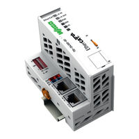
EtherCAT Fieldbus Coupler, ID Switch 100 Mbit/s; digital and analog signals
Brand:
WAGO
| Category:
I/O Systems
| Size: 8.31 MB
Table of Contents
Table of Contents
5
Table of Contents
3
Table of Contents
7
Notes about this Documentation
8
Validity of this Documentation
8
Copyright
8
Symbols
9
Number Notation
11
Font Conventions
11
Table 1: Number Notation
11
Table 2: Font Conventions
11
Important Notes
12
Legal Bases
12
Subject to Changes
12
Personnel Qualifications
12
Use of the 750 Series in Compliance with Underlying Provisions
12
Technical Condition of Specified Devices
13
Disposal
13
2.1.4.1.1 Electrical and Electronic Equipment
13
2.1.4.1.2 Packaging
14
Safety Advice (Precautions)
15
Special Use Conditions for ETHERNET Devices
17
System Description
18
Figure 1: Fieldbus Node (Example)
18
Manufacturing Number
19
Figure 2: Marking Area for Serial Numbers
19
Update
20
Figure 3: Update Matrix up to 2015
20
Figure 4: Update Matrix from 2016
20
Table 3: Legend for Figure "Update Matrix from 2016
20
Storage, Assembly and Transport
21
Assembly Guidelines/Standards
22
Power Supply
23
Overcurrent Protection
23
Isolation
23
Figure 5: Isolation (Example)
23
System Supply
24
Connection
24
Figure 6: System Supply
24
Table 4: Legend for Figure "System Supply
24
Dimensioning
25
Figure 7: System Voltage (Example)
25
Table 5: Alignment
26
Field Supply
28
Connection
28
Figure 8: Field Supply (Sensor/Actuator)
29
Table 6: Legend for Figure "Field Supply (Sensor/Actuator) for ECO Fieldbus
29
Fusing Via Power Supply Module
30
Table 7: Power Supply Modules
30
Figure 9: Supply Module with Fuse Carrier (Example 750-610)
31
Figure 10: Removing the Fuse Carrier
31
Fusing External
32
Figure 11: Opening the Fuse Carrier
32
Figure 12: Changing the Fuse
32
Figure 13: Fuse Modules for Automotive Fuses, Series 282
32
Figure 14: Fuse Modules for Automotive Fuses, Series 2006
33
Figure 15: Fuse Modules with Pivotable Fuse Carrier, Series 281
33
Figure 16: Fuse Modules with Pivotable Fuse Carrier, Series 2002
33
Supply Example
34
Figure 17: Supply Example
34
Table 8: Legend for Figure "Supply Example for Fieldbus Coupler/Controller
35
Power Supply Unit
36
Grounding
37
Grounding the DIN Rail
37
Framework Assembly
37
Insulated Assembly
37
Table 9: WAGO Ground Wire Terminals
37
Grounding Function
38
Figure 18: Carrier Rail Contact (Example)
38
Shielding
39
General
39
Bus Cables
39
Figure 19: Cable Shield at Ground Potential
39
Shielded Signal Lines
40
WAGO Shield Connecting System
40
Figure 20: Examples of the WAGO Shield Connecting System
40
Figure 21: Application of the WAGO Shield Connecting System
40
Device Description
41
View
42
Figure 22: View Ethercat Fieldbus Coupler
42
Table 10: Legend for Figure "View Ethercat Fieldbus Coupler
43
Connectors
44
Device Supply
44
Fieldbus Connection
44
Figure 23: Device Supply
44
Figure 24: RJ-45 Connector
45
Table 11: RJ-45 Connector and RJ-45 Connector Configuration
45
Display Elements
46
Figure 25: Display Elements
46
Table 12: Display Elements Fieldbus Status
46
Table 13: Display Elements Node Status
46
Operating Elements
47
Service Interface
47
Figure 26: Service Interface (Closed and Opened Flap)
47
Table 14: Legend for Figure "Service Interface (Closed and Opened Flap)
47
ID Selection Switch
48
Figure 27: ID Selection Switch (for Example Setting "7")
48
Table 15: EDI Address Structure ("Explicit Device ID")
48
Technical Data
49
Device Data
49
Safe Electrical Isolation
49
Supply
49
Table 16: Technical Data - Device Data
49
Table 17: Technical Data - Safe Electrical Isolation
49
Table 18: Technical Data - Supply
49
Communication
50
Accessories
50
Connection Type
50
Table 19: Technical Data - Communication
50
Table 20: Technical Data - Accessories
50
Table 21: Technical Data - Field Wiring
50
Table 22: Technical Data - Power Jumper Contacts
50
Table 23: Technical Data - Data Contacts
50
Climatic Environmental Conditions
51
Mechanical Strength
51
Table 24: Technical Data - Climatic Environmental Conditions
51
Table 25: Technical Data - Mechanical Strength
51
Approvals
52
Standards and Guidelines
53
Mounting
54
Installation Position
54
Overall Configuration
54
Mounting Onto Carrier Rail
56
Carrier Rail Properties
56
WAGO DIN Rails
57
Spacing
57
Figure 28: Spacing
57
Table 26: WAGO DIN Rails
57
Mounting Sequence
58
Inserting and Removing Devices
59
Inserting the Fieldbus Coupler/Controller
60
Removing the Fieldbus Coupler/Controller
60
Figure 29: Release Tab
60
Inserting the I/O Module
61
Figure 30: Insert I/O Module (Example)
61
Figure 31: Snap the I/O Module into Place (Example)
61
Removing the I/O Module
62
Figure 32: Removing the I/O Module (Example)
62
Connect Devices
63
Data Contacts/Local Bus
63
Figure 33: Data Contacts
63
Power Contacts/Field Supply
64
Figure 34: Example for the Arrangement of Power Contacts
64
Connecting a Conductor to the CAGE CLAMP
65
Figure 35: Connecting a Conductor to a CAGE CLAMP
65
Function Description
66
Starting up the Fieldbus Coupler
66
Start Behavior
67
Process Data Architecture
68
Figure 36: Start Behavior
68
General Mechanisms for Ethercat to Map Process Data
69
Figure 37: Mapping the Process Data
70
Figure 38: Example of the Principle Mapping of Process Data Using
71
Object 0X6000
72
Table 27: Generic Structure of Object 0X6000
72
Object 0X7000
73
Table 28: Example Structure for Object 0X6000 for 750-433 - 4 DI
73
Table 29: Example Structure for Object 0X6000 for 750-467 - 2 AI
73
Table 30: Generic Structure of Object 0X7000
74
Table 31: Example Structure for Object 0X7000 for 750-504 - 4 DO
74
Table 32: Example Structure for Object 0X7000 for 750-550 - 2 AO
74
Object 0Xf100
75
Object 0Xf200
75
Table 33: Structure for Object 0Xf100
75
Table 34: Structure of Object 0Xf200
75
Rxpdo and Txpdo Objects
76
Table 35: Generic Structure of Rx/Txpdo (0X16Xx/0X1Axx)
76
Alternative PDO Index Assignment
77
Table 36: Recommendations for Setting the 0X2100:01
77
Example According to the Modular Device Profile
78
Table 37: Example Output Process Image
79
Table 38: Example Input Process Image
79
Table 39: Object 0Xf100 (Fieldbus Coupler Status Information)
80
Table 40:Object 0Xf200 (Fieldbus Coupler Control Information)
80
Table 41: Object 0X16Ff (Fieldbus Coupler Control PDO)
80
Table 42: Object 0X1Aff (Fieldbus Coupler Status PDO)
81
Table 43: Object 0X6000 (Input Data 750-670)
81
Table 44: Object 0X7000 (Output Data 750-670)
82
Table 45: Object 0X1600 (Rxpdo 750-670)
82
Table 46: Object 0X1A00 (Txpdo 750-670)
83
Table 47: Object 0X6010 (Input Data 750-433)
84
Table 48: Object 0X1A01 (Txpdo 750-433)
84
Table 49: Object 0X7020 (Output Data 750-504)
84
Table 50: Object 0X1602 (Rxpdo 750-504)
84
Table 51: Object 0X7030 (Output Data 750-550)
85
Table 52: Object 0X1603 (Rxpdo 750-550)
85
Table 53: Object 0X6040 (Input Data 750-467)
85
Table 54: Object 0X1A04 (Txpdo 750-467)
85
Table 55: Object 0X1701 (Rxpdo Gap at the End of the Output Process Image, Behind the Do´s)
86
Table 56: Object 0X1B01 ((Txpdo Gap at the End of the Input Process Image, Behind the DI´s)
86
Table 57: Object 0X1C12 (Rxpdo Assignment List for Sync Manager 2)
86
Example According to Linear PDO Indexing
87
Table 59: Example Output Process Image
88
Table 60: Example Input Process Image
88
Table 61: Object 0Xf100 (Fieldbus Coupler Status Information)
89
Table 62:Object 0Xf200 (Fieldbus Coupler Control Information)
89
Table 63: Object 0X1600 (Fieldbus Coupler Control PDO)
89
Table 64: Object 0X1A00 (Fieldbus Coupler Status PDO)
90
Table 65: Object 0X6000 (Input Data 750-670)
90
Table 66: Object 0X7000 (Output Data 750-670)
91
Table 67: Object 0X1601 (Rxpdo 750-670)
91
Table 68: Object 0X1A01 (Txpdo 750-670)
92
Table 69: Object 0X6010 (Input Data 750-433)
92
Table 70: Object 0X1A03 (Txpdo 750-433)
92
Table 71: Object 0X7020 (Output Data 750-504)
93
Table 72: Object 0X1603 (Rxpdo 750-504)
93
Table 73: Object 0X7030 (Output Data 750-550)
93
Table 74: Object 0X1602 (Rxpdo 750-550)
93
Table 75: Object 0X6040 (Input Data 750-467)
94
Table 76: Object 0X1A04 (Txpdo 750-467)
94
Table 77: Object 0X1701
94
Table 78: Object 0X1B01
94
Table 79: Object 0X1C12 (Rxpdo Assignment List for Sync Manager 2)
94
Table 58: Object 0X1C13 (Txpdo Assignment List for Sync Manager 3)
95
Table 80: Object 0X1C13 (Txpdo Assignment List for Sync Manager 3)
95
Object Dictionary
96
Structure "Module Ident
96
Table 81: Structure of "Module Ident" for Digital I/O Modules
96
Object 0X10F3 (Diagnostic History)
97
Table 82: Structure of "Module Ident" for Complex I/O Modules
97
Table 83: Structure of a Diagnostic Entry in Object 0X10F3
98
Table 84: Structure of the Diagnosis History Object 0X10F3
99
Figure 39: Number of Free Slots
100
Figure 40: Acknowledgement of a Diagnostic Message
100
Objects 0X1C32 and 0X1C33
102
Figure 41: Overrun Counter in Subindex 11
102
Objects 0X2000
103
Table 85: Structure of Sync Manager 2 Synchronization Object 0X1C32
103
Table 86: Structure of the Sync Manager 3 Synchronization Object 0X1C33
103
Table 87: Register List Objects 0X2000
104
Objects 0X2010 and 0X2011
105
Table 88: Single Register Access Objects 0X2010, 0X2011
106
Object 0X2100
107
Object 0X2134
107
Table 89: PDO Index Assignment Object 0X2100
107
Objects 0X9000
108
Objects 0Xf030 and 0Xf050
108
Table 90: Explicit Device ID (Upper 8 Bits) Object 0X2134
108
Data Exchange
109
Figure 42: Memory Areas and Data Exchange of the Fieldbus Coupler
109
Arrangement of the Process Data in the PAA/PAE
110
Determining the Process Data Arrangement Using the
111
Ethercat Master
111
Table 91: Process Data Architecture -- Example
111
Table 92: Process Data Objects
112
Controlling the Process Images
113
Fieldbus Coupler Control Word
113
Table 93: Fieldbus Coupler Control Word
113
Fieldbus Coupler Status Word
114
Behaviour of the Fieldbus Coupler During a Cycle Time Overrun
114
Table 94: Fieldbus Coupler Status Word
114
Hot Connect
116
Commissioning
118
Connecting Client PC and Fieldbus Nodes
118
Load XML-File in the Master
118
Testing the Function of the Ethercat Fieldbus Node
119
Testing I/O Modules Using WAGO-I/O-CHECK
120
Diagnostics
121
Fieldbus Coupler Diagnostics
121
LED Signaling
121
Evaluating Fieldbus Status
121
Figure 43: Display Elements
121
Table 95: LED Assignment for Diagnostics
121
Table 96: LED L/A IN, L/A out
122
Table 97: LED RUN
122
Table 98: LED ERR
122
Evaluating Node Status - I/O LED (Blink Code Table)
123
Table 99: Node Status Diagnostics - Solution in Event of Error
123
Figure 44: Node Status - I/O LED Signaling
124
Figure 45: Error Message Coding
124
Table 100: Blink Code Table for the I/O LED Signaling, Error Code 1
126
Table 101: Blink Code Table for the I/O LED Signaling, Error Code 2
127
Table 102: Blink Code Table for the I/O LED Signaling, Error Code 3
127
Table 103: Blink Code Table for the I/O LED Signaling, Error Code 4
128
Table 104: Blink Code Table for the I/O LED Signaling, Error Code 5
129
Table 105: Blink Code Table for the I/O LED Signaling, Error Code 6
129
I/O Module Diagnostics
130
Diagnostic Control Word
130
Diagnostic Status Word
131
Table 106: Diagnostic Control Word
131
Table 107: Diagnostic Status Word
132
Behavior of the Fieldbus Coupler During Interruption of Operations
133
Loss of Power
133
Loss of Fieldbus
133
Local Bus Error
133
Figure 46: Behavior During a Local Bus Error
134
Behavior During Other Operating Errors
135
Configuration Error in a Sync Manager
135
Table 108: Settings for the Sync Managers SM0 and SM1
136
Table 109: Settings for the Sync Managers SM2 and SM3
137
Table 110: Sync Manager Length Error EMCY Data
137
Table 111: Sync Manager Address Error EMCY Data
137
Table 112: Sync Manager Settings Error EMCY Data
137
Interruption of the Cyclical Process Data Exchange
138
Figure 47: Error Behavior of the Process Data Watchdog
138
Errors During Coe Accesses
139
Fieldbus Communication
140
Ethercat
140
General
140
Network Structure
141
Transmission Medium
141
Network Topology
141
Couplers
142
Network Communication
142
Communication Principle
142
Addressing
142
Configuration
143
Ethercat State Machine (ESM)
144
Figure 48: Status Diagram of an Ethercat Slave
144
Table 113: Ethercat State Machine (ESM)
146
Synchronization Using Distributed Clocks
147
Performance
148
Diagnostics
148
Ethercat Interfaces
149
Slave Information Interface (SII)
149
Coe Interface (CAN Application Layer over Ethercat )
149
Table 114: Coe Components
150
Table 115: Command Object Structure
152
O Modules
153
Overview
153
Process Data Architecture for Ethercat
154
Digital Input Modules
155
Channel Digital Input Module with Diagnostics
155
Channel Digital Input Modules
155
Table 116: 1 Channel Digital Input Module with Diagnostics
155
Table 117: 2 Channel Digital Input Modules
155
Table 118: 2 Channel Digital Input Module with Diagnostics
155
Channel Digital Input Module with Diagnostics and Output Process Data
156
Table 119: Diagnostic Data of 2 Channel Digital Input Module with Diagnostics in the Diagnostic Status Word
156
Table 120: 2 Channel Digital Input Module with Diagnostics and Output Process Data
156
Table 121: Diagnostic Data 2 Channel Digital Input Module with Diagnostics in the Diagnostic Status Word and Output Process Data
156
Channel Digital Input Modules
157
Table 122: 4 Channel Digital Input Modules
157
Table 123: 8 Channel Digital Input Modules
157
Table 124: 16 Channel Digital Input Modules
157
Digital Output Modules
158
Channel Digital Output Module with Input Process Data
158
Channel Digital Output Modules
158
Table 125: 1 Channel Digital Output Module with Input Process Data
158
Table 126: 2 Channel Digital Output Modules
158
Channel Digital Input Modules with Diagnostics and Input Process Data
159
Table 127: 2 Channel Digital Input Modules with Diagnostics and Input Process Data
159
Table 128: Diagnostic Data 2 Channel Digital Input Modules with Diagnostics in the Diagnostic Status Word
159
Table 129: 2 Channel Digital Input Modules with Diagnostics and Input Process Data 75X-506
159
Table 130: Diagnostic Data 2 Channel Digital Input Modules with Diagnostics in the Diagnostic Status Word
159
Channel Digital Output Modules
160
Channel Digital Output Modules with Diagnostics and Input Process Data
160
Table 131: 4 Channel Digital Output Modules
160
Table 132: 4 Channel Digital Output Modules with Diagnostics and Input Process Data
160
Table 133: 4 Channel Digital Output Modules with Diagnostics in the Diagnostic Status Word
160
Table 135: 8 Channel Digital Output Modules with Diagnostics and Input Process Data
160
Channel Digital Output Module
161
Channel Digital Output Modules with Diagnostics and Input Process Data
161
Table 134: 8 Channel Digital Output Module
161
16 Channel Digital Output Modules
162
Table 136: 8 Channel Digital Output Modules with Diagnostics in the Diagnostic Status Word
162
Table 137: 16 Channel Digital Output Modules
162
Channel Digital Input/Output Modules
163
Analog Input Modules
163
Channel Analog Input Modules
163
Table 138: 8 Channel Digital Input/Output Modules
163
Table 139: 1 Channel Analog Input Modules
163
Channel Analog Input Modules
164
Channel Analog Input Modules HART
164
Table 140: 2 Channel Analog Input Modules
164
Channel Analog Input Modules
165
Table 141: 2-Channel Analog Input Modules HART
165
Table 142:: 2 Channel Analog Input Modules HART + 6 Bytes Mailbox
165
Table 143: 4 Channel Analog Input Modules
165
Channel Analog Input Modules
166
Table 144: 8 Channel Analog Input Modules
166
3-Phase Power Measurement Module
167
Table 145: 3-Phase Power Measurement Module
167
Table 146: 3-Phase Power Measurement Modules 750-494, -495
168
Analog Output Modules
169
Channel Analog Output Modules
169
Table 147: 2 Channel Analog Output Modules
169
Table 148: 4 Channel Analog Output Modules
169
Channel Analog Output Modules
170
Specialty Modules
170
Table 149: 8 Channel Analog Output Modules
170
Counter Modules
171
Table 150: Counter Modules 750-404, (and All Variations Except of /000-005)
171
Table 151: Counter Modules 750-404/000-005, 753-404/000-005
171
Table 152: Counter Modules 750-633
172
Table 153: Counter Modules 750-638, 753-638
172
Pulse Width Modules
173
Serial Interface Modules with Alternative Data Format
173
Table 154: Pulse Width Modules 750-511, (and All Variations), 753-511
173
Serial Interface Modules with Standard Data Format
174
Serial Interface Modules
174
Table 155: Serial Interface Modules with Alternative Data Format
174
Table 156: Serial Interface Modules with Standard Data Format
174
Data Exchange Module
175
SSI Transmitter Interface Modules
175
Table 157: Serial Interface Modules 750-652, 753-652
175
Table 158: Data Exchange Module 750-654, -654/000-001
175
Table 159: SSI Transmitter Interface Modules
175
Incremental Encoder Interface Modules
176
Table 160: Incremental Encoder Interface Modules
177
Table 161: Incremental Encoder Interface Modules 750-634
177
Table 162: Incremental Encoder Interface Modules
177
DC-Drive Controller
178
Table 163: Digital Pulse Interface Modules 750-635, 753-635
178
Table 164: DC-Drive Controller 750-636, -636/000-700, -636/000-800
178
11.2.5.10 Stepper Controller
179
Table 165: Stepper Controller 750-670, -671, -672
179
11.2.5.11 RTC Module
180
11.2.5.12 DALI/DSI Master Module
180
11.2.5.13 DALI Multi-Master Module
180
Table 166: RTC Module 750-640
180
Table 167: DALI/DSI Master Module 750-641
180
Table 168: DALI Multi-Master Module 753-647 in the "Easy" Mode
181
Table 169: DALI Multi-Master Module 753-647 in the "Full" Mode
182
11.2.5.14 Enocean Radio Receiver
183
11.2.5.15 MP Bus Master Module
183
Table 170: Enocean Radio Receiver 750-642
183
Table 171: MP Bus Master Module 750-643
183
Bluetooth ® RF-Transceiver
184
Table 172: Bluetooth ® RF-Transceiver 750-644
184
11.2.5.17 Vibration Velocity/Bearing Condition Monitoring VIB I/O
185
11.2.5.18 AS-Interface Master Module
185
Table 173: Vibration Velocity/Bearing Condition Monitoring VIB I/O 750-645
185
Table 174: AS-Interface Master Module 750-655, 753-655
186
System Modules
187
System Modules with Diagnostics
187
Filter Module
187
Table 175: System Modules with Diagnostics 750-606
187
Table 176: System Modules with Diagnostics 750-610, -611
187
Table 177: Filter Modules 750-624/020-002, 750-626/020-002
187
Binary Space Module
188
Table 178: Binary Space Module
188
Use in Hazardous Environments
189
Marking Configuration Examples
190
Marking for Europe According to ATEX and Iecex
190
Figure 49: Marking Example According to ATEX and Iecex
190
Figure 50: Text Detail - Marking Example According to ATEX and Iecex
190
Table 179: Description of Marking Example According to ATEX and Iecex
191
Figure 51: Marking Example for Approved Ex I I/O Module According to
192
Figure 52: Text Detail - Marking Example for Approved Ex I I/O Module According to ATEX and Iecex
192
Table 180: Description of Marking Example for Approved Ex I I/O Module According to ATEX and Iecex
193
Marking for the United States of America (NEC) and Canada (CEC)
194
Figure 53: Marking Example According to NEC
194
Figure 54: Text Detail - Marking Example According to NEC 500
194
Table 181: Description of Marking Example According to NEC 500
194
Figure 55: Text Detail - Marking Example for Approved Ex I I/O Module
195
Figure 56: Text Detail - Marking Example for Approved Ex I I/O Module
195
Table 182: Description of Marking Example for Approved Ex I I/O Module
195
Table 183: Description of Marking Example for Approved Ex I I/O Modules
195
Figure 57: Text Detail - Marking Example for Approved Ex I I/O Modules
196
Table 184: Description of Marking Example for Approved Ex I I/O Modules
196
Installation Regulations
197
Special Notes Regarding Explosion Protection
197
Special Notes Regarding ANSI/ISA Ex
199
Appendix
200
Ethercat ® Object Dictionary
200
Table 185: Ethercat ® Object Dictionary
200
Table 186: Ethercat ® Object Dictionary
206
AL Status Codes
208
Table 187: al Status Codes
208
SDO Abort Codes
209
Table 188: SDO Abort Codes
209
EMCY Codes
210
Table 189: EMCY Codes
210
List of Figures
211
List of Tables
213
Advertisement
Advertisement
Related Products
WAGO 750-352/040-000
WAGO 750-370
WAGO 750-342
WAGO 750-344
WAGO 750-345
WAGO 750-346
WAGO 750-341
WAGO 750-337
WAGO 750-338
WAGO 750-312
WAGO Categories
I/O Systems
Control Unit
Power Supply
Switch
Controller
More WAGO Manuals
Login
Sign In
OR
Sign in with Facebook
Sign in with Google
Upload manual
Upload from disk
Upload from URL