Lightware MMX4x2-HDMI User Manual
Standalone multimedia matrix switcher
Hide thumbs
Also See for MMX4x2-HDMI:
- User manual (98 pages) ,
- Quick start manual (2 pages) ,
- User manual (172 pages)

Subscribe to Our Youtube Channel
Related Manuals for Lightware MMX4x2-HDMI


Summary of Contents for Lightware MMX4x2-HDMI
- Page 1 User’s Manual MMX4x2-HDMI MMX4x2-HT200 MMX4x2-HDMI-USB20-L Standalone Multimedia Matrix Switcher v3.0 16-07-2020 ...
- Page 2 MMX4x2 series – User's Manual Important Safety Instructions Waste Electrical & Electronic Equipment Common Safety Symbols WEEE Class II apparatus construction. Symbol Description This marking shown on the product or its literature, The equipment should be operated only from the power source indicates that it should not be disposed with other indicated on the product.
- Page 3 The following symbols and markings are used in the document: All presented functions refer to the indicated products. The descriptions Lightware Visual Engineering supports green technologies and have been made during testing these functions in accordance with the Eco-friend mentality. Thus, this document is made for digital usage...
-
Page 4: Table Of Contents
2.6.3. Enable DHCP (Static) IP Address ........... 17 5.12.1. Opening the Miniweb ..............56 2.6.4. Reset to Factory Default Settings ........... 17 5. SOFTWARE CONTROL - LIGHTWARE DEVICE CONTROLLER ..33 5.12.2. The Default Status Page ............... 57 2.6.5. Reseting the Device ................. 17 5.1. Install and Upgrade ..............33 5.12.3. Miniweb Customization .............. - Page 5 MMX4x2 series – User's Manual 6.4. A/V Port Settings ...............63 7.5.3. Querying the Video Crosspoint Setting .......... 75 7.7.5. Mute/Unmute Analog Audio Output ..........86 6.4.1. Switch an Input to the Outputs ............63 7.5.4. Switching Video Input ..............75 7.7.6. Analog Audio Input Level Settings by Exact Values ...... 87 6.4.2. Mute Output ..................
- Page 6 7.16.4. Setting the Output Level of a GPIO Pin ........101 11.3. Input/Output Port Numbering ..........126 7.16.5. Toggling the Level of a GPIO Pin ..........101 7.17. USB 2.0 Switch Configuration ..........102 11.3.1. MMX4x2-HDMI and MMX4x2-HDMI-USB20-L......126 7.17.1. Setting the Active USB Host ............102 11.3.2. MMX4x2-HT200 ................127 7.17.2. Power Switch Delay ..............102 11.4. Content of Backup File ............127...
-
Page 7: Introduction
1. Introduction MMX4x2 series – User's Manual I ntroduction Thank you for choosing Lightware’s MMX4x2 series device. In the first chapter we would like to introduce the device highlighting the most important features in the coming sections. ç Description ç Compatible Devices ç... -
Page 8: Description
Multimedia matrix HDMI: model with HDMI-type I/O ports HT200: model with one TPS input About the Serial Number Lightware devices contain a label indicating the unique serial number of the product. The structure is the following: Phoenix Combicon Rack ears (2x) with ®... -
Page 9: Optional Accessories
TBP6 Button Panel Rack shelf Under Desk-kit double Automation Panel PSU2x rack-mountable Power Supply Unit Recommended for MMX4x2-HDMI and MMX4x2-HT200 models only. The assembling of certain accessories can be found in the Mounting Options section. Standalone Application - MMX4x2-HDMI-USB20-L #new 1.5. Typical Applications... -
Page 10: Features
Priority number can be set for each input port and the feature allows 1.6.1. MMX4x2-HDMI-USB20-L Features to set various modes for the automatic input selection (First detect, Last detect, Priority mode). DIFFERENCE: The following features refer to the MMX4x2-HDMI-USB20-L model only. #new Audio Embedder and De-embedder Function 4x1 USB 2.0 Switch The analog audio can be embedded to HDMI outputs and embedded audio can be routed to the The USB 2.0 layer provides the switching of four external USB peripherals (e.g. -
Page 11: Product Overview
P roduct Overview The following sections are about the physical structure of the device, input/output ports and connectors, buttons and status LEDs. ç MMX4x2-HT200 ç MMX4x2-HDMI ç MMX4x2-HDMI-USB20-L ç Front Panel LEDs ç Rear Panel LEDs ç Front Panel Buttons... -
Page 12: Mmx4X2-Ht200
2. Product Overview MMX4x2 series – User's Manual 2.1. MMX4x2-HT200 Rear View Front View 5 6 7 8 9 12V DC 1A input port Local power in; connect the output of the supplied 12V DC power Audio input port 5-pole Phoenix connector for balanced analog audio. -
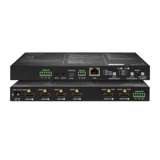
Page 13: Mmx4X2-Hdmi
2. Product Overview MMX4x2 series – User's Manual 2.2. MMX4x2-HDMI Rear View Front ViewI 5 6 7 8 9 12V DC 1A input port Local power in; connect the output of the supplied 12V DC power Audio input port 5-pole Phoenix connector for balanced analog audio. -
Page 14: Mmx4X2-Hdmi-Usb20-L
2. Product Overview MMX4x2 series – User's Manual 2.3. MMX4x2-HDMI-USB20-L Rear View Front View #new RS-232 (#2) 3-pole Phoenix connector for controlling the device with LDC, third- party control systems, or third-party device control. Pin assignment can be found in the RS-232 Connector section. -
Page 15: Front Panel Leds
2. Product Overview MMX4x2 series – User's Manual 2.4. Front Panel LEDs 2.5. Rear Panel LEDs Status LEDs HDMI input LEDs LIVE LED Signal is not present on input. The device is not powered. Signal is present on input. green blinking slow Device is powered and operational. -
Page 16: Front Panel Buttons
The sequence is the following for each device. RESET LIVE IN 1 AUDIO OUT IN 2 OUT 1 AUTO IN 3 MMX4x2-HDMI: #autoselect OUT 2 AUTO IN 4 OUT1 OUT2 SET AUDIO O1 (HDMI OUT 1) VIDEO SELECT... -
Page 17: Enable Dhcp (Static) Ip Address
The device has a static IP address as a factory default setting. If this setting does not fit Lightware Device Updater (LDU) software. Do not use this option with LDU2 software. to the circumstances during install or usage, DHCP can be enabled from the front panel: RESET Step 1. -
Page 18: Installation
3. Installation MMX4x2 series – User's Manual Installation The chapter is about the installation of the device and connecting to other appliances, presenting also the mounting options and further assembly steps. ç Mounting Options ç Electrical Connections ç... -
Page 19: Mounting Options
UD-kit is the same as for UD-kit double. To mount the matrix Lightware supplies optional accessories for different usage. There are two kinds of mounting kits with similar fixing method. The receiver has two mounting holes with inner thread on the bottom side;... -
Page 20: Electrical Connections
Always use the supplied 12V power adaptor. Warranty void if damage occurs due to use of a Lightware recommends the termination of LAN cables on the basis of TIA/EIA T 568 A or TIA/EIA T 568 B different power source. -
Page 21: Ir Connector
IR detector and IR emitter can be connected to the matrix with TRS (Tip, Ring, and Sleeve) DIFFERENCE: This section refers to MMX4x2-HDMI-USB20-L model only. #new connectors. They are also known as (3,5 mm or approx. 1/8”) audio jack, phone jack, phone plug, The matrix switcher contains a 8-pole Phoenix connector with six GPIO pins, which operates at TTL digital and mini-jack plug. -
Page 22: Connecting Steps
Connect the IR detector to the IR IN port of the matrix. Connect the power adaptor to the DC input on the matrix first, then to the AC power socket. Optionally connect a device to the GPIO port (e.g. Lightware’s TBP6-EU-K button panel for room Power GPIO control options). -
Page 23: Device Concept
4. Device Concept MMX4x2 series – User's Manual Device Concept The following chapter describes the features of the device with a few real-life examples. ç Compact Size Matrix Concept ç Video Interface ç Consuming Electronics Control (CEC) Interface ç... -
Page 24: Compact Size Matrix Concept
Summary of the interfaces - MMX4x2-HT200 INFO: Only MMX4x2-HT200 model has TPS input. MMX4x2-HDMI model has HDMI+analog audio inputs Port diagram of MMX4x2-HT200 matrix switcher and HDMI+analog audio outputs. The device has four video input ports (one TPS, three HDMI) and the 4x2 HDMI crosspoint routes the video signal further to the two video output ports (HDMI). -
Page 25: Consuming Electronics Control (Cec) Interface
4. Device Concept MMX4x2 series – User's Manual 4.3. Consuming Electronics Control (CEC) Interface Audio De-embedding The matrix has a built-in audio de-embedder which means the device is able to de-embed audio from its Consumer Electronics Control (CEC) is a bi-directional communication, defined in the HDMI standard. This HDMI outputs to its analog audio output port. -
Page 26: The Autoselect Feature
I1 (TPS IN 1) Port with Port with priority priority 1 has a 1 is selected Priorities can be set in Lightware Device Controller software, see related settings in the HDMI Video Output valid signal? section. Port with Port with priority... -
Page 27: Usb Interface
The device can be controlled over front panel USB port (mini B-type connector). This interface supports only connected to the USB A-type ports. The user can select to switch the USB peripherals to the PC or to the LW3 protocol. The interface can be used to establish a connection to Lightware Device Controller software. laptop. -
Page 28: Tps Interface
4. Device Concept MMX4x2 series – User's Manual 4.8. TPS Interface 4.9. RS-232 Serial Interface DIFFERENCE: This section refers to the MMX4x2-HT200 model only. 4.9.1. Technical Background The MMX4x2-HT200 model is built with TPS (Twisted Pair Single) interface which are using HDBaseT ATTENTION! Only MMX4x2-HT200 model has TPS serial link port. -
Page 29: Recognizer
4. Device Concept MMX4x2 series – User's Manual 4.9.2. RS-232 Recognizer Command Injection Mode In this mode, the matrix works as a TCP/IP <-> RS-232 bidirectional converter. The TCP/IP data signal is This tool is able to recognize and store the incoming RS-232 message until the previously defined string converted to RS-232 data and vice versa. -
Page 30: Ir Interface
4. Device Concept MMX4x2 series – User's Manual 4.10. IR Interface The Concept An IR detector is attached to the Infrared input port of the Matrix and IR signals are sent by the Remote ATTENTION! The device has no built-in Infrared receiver and transmitter. For the complete usage attach controller. -
Page 31: Gpio Interface
You can establish the connection between the is able to react according to the pre-defined settings. Lightware Device Controller controller/controllable device and the matrix switcher by the 8-pole Phoenix connector. The direction of the contains a user-friendly software tool and allows to create Events by defining a six pin is configurable independently from each other. - Page 32 4. Device Concept MMX4x2 series – User's Manual Sources and Destinations The EDID memory consists of four parts: ▪ Factory EDID list shows the pre-programmed EDIDs (F1-F120). ▪ Dynamic EDID list shows the display device connected to the device's outputs. The unit stores the last display devices’...
-
Page 33: Software Control - Lightware Device Controller
Available for Windows and macOS Available for Windows The device can be controlled by a computer through Ethernet and RS-232 interfaces by the Lightware Device Controller (LDC). The software can be installed on a Windows PC or macOS. The application and the User’s Manual... -
Page 34: Running The Ldc
5. Software Control - Lightware Device Controller MMX4x2 series – User's Manual 5.3. Establishing the Connection Step 2. Set the desired update setting in the Options section. ▪ If you do not want to check for the updates Step 1. - Page 35 5. Software Control - Lightware Device Controller MMX4x2 series – User's Manual Step 3. Select the unit from the discovered Ethernet devices or under Serial devices; when the device is connected through RS-232 click on the Query button next to the desired serial port to display the device’s name and serial number.
-
Page 36: Crosspoint Menu
5. Software Control - Lightware Device Controller MMX4x2 series – User's Manual 5.4. Crosspoint Menu Audio input ports Each tile represents an audio input port. The A1 and A2 are logical audio ports, they mean the audio channel of the selected TPS/HDMI inputs. The... -
Page 37: Presets Tab
5. Software Control - Lightware Device Controller MMX4x2 series – User's Manual 5.4.2. Presets Tab 5.4.3. Port Tiles The colors of the port tiles and the displayed icons represent different states and information: Port name Port icon HDMI OUT1... -
Page 38: Port Properties Windows
5. Software Control - Lightware Device Controller MMX4x2 series – User's Manual 5.5. Port Properties Windows 5.5.2. HDMI Video Input Clicking on the HDMI video input port icon results opening the Port properties window. The most important Clicking on the port tile opens the Port properties window. This section shows the available settings and information and settings are available from the panel. -
Page 39: Hdmi Video Output
5. Software Control - Lightware Device Controller MMX4x2 series – User's Manual 5.5.3. HDMI Video Output ▪ Signal type: Auto / DVI / HDMI - The outgoing signal format can be selected by a drop-down menu; HDCP mode: Auto / Always - The transmitter forces the source sent the signal without encryption if the ▪... -
Page 40: Digital Audio Input
5. Software Control - Lightware Device Controller MMX4x2 series – User's Manual 5.5.4. Digital Audio Input 5.5.5. Analog Audio Input A1 and A2 inputs are logical audio ports which are the audio channels of the selected HDMI input ports. -
Page 41: Digital Audio Output
5. Software Control - Lightware Device Controller MMX4x2 series – User's Manual 5.5.6. Digital Audio Output The port properties windows of the video and audio outputs are mirrored. For example the same window will be opened when you select the HDMI OUT1 on the Video or the Audio sections. The available settings can... -
Page 42: Cec Tool
5. Software Control - Lightware Device Controller MMX4x2 series – User's Manual 5.6. CEC Tool Drop-down Containing the basic CEC commands, most of them are displayed on the command list graphical interface, too (on the left side). Click on the Send button to execute The device is able to send and receive Consumer Electronic Control (CEC) commands. -
Page 43: Diagnostic Tools
Frame detector window selected input port. Lightware’s Frame Detector function works like a signal analyzer and makes possible to determine the exact Clock Source video format that is present on the port, thus helps to identify many problems. E.g. actual timing parameters may differ from the expected and this may cause some displays to drop the picture. -
Page 44: Cablediagnostics
5. Software Control - Lightware Device Controller MMX4x2 series – User's Manual 5.7.3. Cable Diagnostics Table and Chart Views Cable diagnostics can be displayed in advanced modes as well. Two ways are available: table view and chart DIFFERENCE: This tool is available for MMX4x2-HT200 model only. -
Page 45: Edid Menu
5. Software Control - Lightware Device Controller MMX4x2 series – User's Manual 5.8. EDID Menu 5.8.1. EDID Operations Advanced EDID Management can be accessed by selecting the EDID menu. There are two panels: left one Changing Emulated EDID contains Source EDIDs, right one contains Destination places where the EDIDs can be emulated or copied. -
Page 46: Edid Summary Window
The software resolves the raw EDID and displays it as readable information to the user. All descriptors can be edited, and saved in an EDID file, or uploaded to the User memory. For more details about EDID Editor please visit our website (www.lightware.com) and download the EDID Editor Application note. -
Page 47: Creating An Edid - Easy Edid Creator
Since above mentioned Advanced EDID Editor needs more complex knowledge about EDID, 5.9.1. RS-232 Create Lightware introduced a wizard-like interface for fast and easy EDID creation. With Easy EDID DIFFERENCE: MMX4x2-HDMI-USB20-L model is assembled with two local RS-232 ports. TPS port can be Creator it is possible to create custom EDIDs in four simple steps. -
Page 48: Ethernet
MMX4x2 series – User's Manual 5.9.2. Ethernet 5.9.3. GPIO DIFFERENCE: MMX4x2-HDMI-USB20-L model has three RJ-45 connectors for Ethernet. TPS port can be DIFFERENCE: This section refers to the MMX4x2-HDMI-USB20-L model only. found on MMX4x2-HT200 model only. The GPIO port has 6 pins, which operate at TTL digital signal levels and can be controlled by LDC or protocol commands. -
Page 49: Infra
5. Software Control - Lightware Device Controller MMX4x2 series – User's Manual 5.9.4. Infra Description Function ATTENTION! The device has no built-in Infrared receiver and transmitter. For the complete usage attach Code number. an IR emitter unit to the IR OUT and an IR detector unit to the IR IN connectors. -
Page 50: Usbswitch
MMX4x2 series – User's Manual 5.9.5. USBSwitch Ports User can set the name and command injection port to each sources and destinations. For more details DIFFERENCE: This section refers to the MMX4x2-HDMI-USB20-L model only. #new about IR interface see the IR Interface section. -
Page 51: Event Manager
(e.g. built under the desk). For more details and examples about Event Manager please visit our website (www.lightware.com) and download Event Manager user's guide in the Downloads section. The Event manager can be configured to perform an action if a condition has been detected. E.g. the desired setup is that after a certain type of signal has been detected on I1 port, the port has to be switched to O1. -
Page 52: Create Or Modify An Event
5. Software Control - Lightware Device Controller MMX4x2 series – User's Manual 5.10.2. Create or Modify an Event 5.10.3. Special Tools and Accessories Wizard Mode The Name of the Event The wizard mode lists the most common conditions and actions, so the The name of a port can be changed by typing the new name and clicking the Set button. -
Page 53: Clear One Or More Event(S)
...<command ><\x0d\x0a> The MMX4x2-HDMI matrix is connected to a projector by the HDMI out 1 port. The matrix is also connected In the current case the command is: PWR0\x0d\x0a to the projector by the RS-232 port and can send commands via the serial line. The task is to turn on the projector when signal is detected on the HDMI out 1 port. -
Page 54: Settings Menu
5. Software Control - Lightware Device Controller MMX4x2 series – User's Manual 5.11. Settings Menu 5.11.2. Network 5.11.1. Status Network tab in Settings menu Status tab in Settings menu IP address and DHCP settings can be set on this tab. Always press the Apply settings button to save changes. -
Page 55: System
5. Software Control - Lightware Device Controller MMX4x2 series – User's Manual 5.11.4. System System tab in Settings menu Three functions are available under System tab: ▪ Download system log - saving the file of the device. -
Page 56: The Built-In Miniweb
5. Software Control - Lightware Device Controller MMX4x2 series – User's Manual 5.12. The Built-in Miniweb 5.12.1. Opening the Miniweb The Miniweb is available by: DEFINITION: The miniweb is a dedicated location in the memory where an HTML file can be uploaded to. -
Page 57: The Default Status Page
5. Software Control - Lightware Device Controller MMX4x2 series – User's Manual 5.12.2. The Default Status Page Customized HTML The default control page can be replaced in the LDC; navigate to the Settings/Status page. Custom HTML file If there is no control page uploaded, the default status page will be displayed (which is also available by can be uploaded by pressing the Choose file button. -
Page 58: Configuration Cloning (Backup Tab)
Step 3. The file is checked and the result will be displayed in the textbox below. If the file is correct, the The configuration cloning of Lightware LW3 devices is a simple method that eliminates the need to repeatedly settings can be restored. -
Page 59: Create And Restore Backups From The Device Memory
5. Software Control - Lightware Device Controller MMX4x2 series – User's Manual 5.13.4. Create and Restore Backups from the Device Memory 5.14. Advanced View Window MMX4x2 series matrix is able to store backups in its own memory and can be recalled from there so user does not need to save backup files to the local computer. -
Page 60: Lw2 Programmers' Reference
MMX4x2 series – User's Manual 6.1. Protocol Description The protocol description hereinafter stands for Lightware protocol. The commands can be sent to the device in RAW format via the TCP/IP port no. 10001. The receiver accepts commands surrounded by curly brackets - { } - and responds data surrounded by round brackets - ( ) - only if a command was successfully executed. -
Page 61: Instructions For The Terminal Application Usage
6. LW2 Programmers' Reference MMX4x2 series – User's Manual 6.2. Instructions for the Terminal Application Usage 6.3. General LW2 Commands 6.3.1. View Product Type Terminal Application The device responds its name. The LW2 protocol commands can be applied to the receiver using a terminal application. -
Page 62: Connection Test
6. LW2 Programmers' Reference MMX4x2 series – User's Manual 6.3.4. Connection Test 6.3.7. View Installed Board Simple test to see if the connection is established successfully. Shows the hardware name and revision of the installed cards. Command and Response Command and Response ... -
Page 63: Query Health Status
6. LW2 Programmers' Reference MMX4x2 series – User's Manual 6.3.10. Query Health Status 6.4. A/V Port Settings Internal voltages and measured temperature values are shown. 6.4.1. Switch an Input to the Outputs Command and Response #status Switching an input <in>... -
Page 64: Mute Output
6. LW2 Programmers' Reference MMX4x2 series – User's Manual 6.4.2. Mute Output 6.4.5. Unlock Output Mute the <out> output. The output signal is turned off. Unlocking an output port. The connection on output can be changed. Command and Response #mute #lock #unmute #unlock... -
Page 65: View Crosspoint Size
6. LW2 Programmers' Reference MMX4x2 series – User's Manual 6.4.7. View Crosspoint Size 6.4.9. Change the Audio Autoselect Mode Shows the physical crosspoint size. The autoselect mode of the audio outputs can be changed. Command and Response Command and Response ... -
Page 66: Change The Audio Input Priorities
6. LW2 Programmers' Reference MMX4x2 series – User's Manual 6.4.11. Change the Audio Input Priorities 6.5. Network Configuration The settings of audio input priority can be changed as follows. 6.5.1. Query the Current IP Status Command and Response The IP address settings can be queried as follows. #dhcp #ipaddress #network ... -
Page 67: Set The Subnet Mask
MMX4x2 series – User's Manual 6.5.3. Set the Subnet Mask 6.6. GPIO Port Configuration Subnet mask can be set as follows. DIFFERENCE: This section refers to the MMX4x2-HDMI-USB20-L model only. #new Command and Response 6.6.1. Setting the Level and Direction for Each Pins {IP_NETMASK=<subnet_mask>} GPIO pins can be configured as follows. -
Page 68: Lw2 Commands - Quick Summary
6. LW2 Programmers' Reference MMX4x2 series – User's Manual 6.7. LW2 Commands – Quick Summary General LW2 Commands View Product Type Unlock Output {i} {+<<out>•<layer>} Query Control Protocol View Connection State on the Output {P_?} ... -
Page 69: Lw3 Programmers' Reference
7. LW3 Programmers’ Reference MMX4x2 series – User's Manual L W3 Programmers’ Reference The device can be controlled through Lightware 3 (LW3) protocol commands to ensure the compatibility with other Lightware products. The supported LW3 commands are described in this chapter. ç Overview ç... -
Page 70: Overview
‘nodes’, ‘properties’ and ‘methods’. The VIDEO Advanced View of the Lightware Device Controller software is the perfect tool for browsing and learning how XP the LW3 protocol can be used in practice. -
Page 71: Legend For The Control Commands
7. LW3 Programmers’ Reference MMX4x2 series – User's Manual 7.3.3. Legend for the Control Commands SET command The SET command can be used to modify the value of a property. Use the dot character (.) when addressing Command and Response –... -
Page 72: Escaping
7. LW3 Programmers’ Reference MMX4x2 series – User's Manual 7.3.7. Escaping Subscribe to a Node Unsubscribe from a Node ç OPEN /MEDIA/VIDEO ç CLOSE /MEDIA/VIDEO DEFINITION: An escape sequence is a sequence of characters that does not represent itself when used inside a character or string literal, but is translated into another character or a sequence of characters. -
Page 73: System Commands
7. LW3 Programmers’ Reference MMX4x2 series – User's Manual 7.4. System Commands 7.4.4. Querying the Firmware Version Command and Response #firmwareversion 7.4.1. Setting the Device Label ç GET·/SYS/MB.FirmwareVersion INFO: The device label can be changed to a custom text in the Status tab of the LDC software. -
Page 74: Video Port Settings
7. LW3 Programmers’ Reference MMX4x2 series – User's Manual 7.5. Video Port Settings The Most Common Received Port Status Responses INFO: Video port numbering can be found in the Input/Output Port Numbering section. 7.5.1. Querying the Status of the Input Ports Unlocked, T00AA No emb. -
Page 75: Querying The Status Of The Output Ports
7. LW3 Programmers’ Reference MMX4x2 series – User's Manual 7.5.2. Querying the Status of the Output Ports 7.5.5. Querying the Video Autoselect Settings Command and Response #portstatus Command and Response #autoselect ç GET·/MEDIA/VIDEO/XP.DestinationPortStatus ç GET·/MEDIA/VIDEO/XP.DestinationPortAutoselect pr·/MEDIA/VIDEO/XP.DestinationPortStatus=<out1_state>;<out2_state> pr·/MEDIA/VIDEO/XP.DestinationPortAutoselect=<out1_set>;<out2_set>;<out3_set> æ æ... -
Page 76: Querying The Input Port Priority
7. LW3 Programmers’ Reference MMX4x2 series – User's Manual 7.5.7. Querying the Input Port Priority 7.5.8. Changing the Input Port Priority Command and Response Command and Response ç GET·/MEDIA/VIDEO/XP.PortPriorityList ç CALL·/MEDIA/VIDEO/XP:setAutoselectionPriority (<in>(<out>):<prio>) æ pr·/MEDIA/VIDEO/XP.PortPrioirtyList= æ mO·/MEDIA/VIDEO/XP:setAutoselectionPrioirty <out1_list>;<out2_list> The response shows the priority of each output one after another. The priority number can be from 0 to 3; 0 Parameters is the highest- and 3 is the lowest priority. -
Page 77: Lock An Input Port
7. LW3 Programmers’ Reference MMX4x2 series – User's Manual 7.5.11. Lock an Input Port 7.5.15. Lock an Output Port Command and Response #lock #unlock #mute #unmute Command and Response ç CALL·/MEDIA/VIDEO/XP:lockSource( <in> ç CALL·/MEDIA/VIDEO/XP:lockDestination( <out> æ mO·/MEDIA/VIDEO/XP:lockSource æ mO·/MEDIA/VIDEO/XP:lockDestination Example Example ç... -
Page 78: Hdcp Setting (Output Port)
7. LW3 Programmers’ Reference MMX4x2 series – User's Manual 7.5.18. HDCP Setting (Output Port) 7.5.19.2. The Clock Frequency of the Test Pattern Command and Response HDCP capability can be set to Auto/Always on the output ports, thus, non-encrypted content can be transmitted to a non-HDCP compliant display. -
Page 79: Hdmi Mode Settings (Output Port)
7. LW3 Programmers’ Reference MMX4x2 series – User's Manual 7.5.20. HDMI Mode Settings (Output Port) 7.5.22. TPS Mode Settings Command and Response #signaltype DIFFERENCE: The command is valid for MMX4x2-HT200 model only. SET·/MEDIA/VIDEO/<out>.HdmiModeSetting=<hdmi_mode> The TPS working mode between the transmitter and the receiver is determined by the mode set in them. ç... -
Page 80: Audio Port Settings Frm Firmware V1.2.0
7. LW3 Programmers’ Reference MMX4x2 series – User's Manual 7.6. Audio Port Settings frm Firmware v1.2.0 Example and Explanation (for input 3, M000F): ATTENTION! The audio port setting commands depend on the installed firmware version of the device. If your device is installed with firmware v1.1.0, see the Audio Port Settings for Firmware v1.1.0 section. -
Page 81: Querying The Status Of Destination Port
7. LW3 Programmers’ Reference MMX4x2 series – User's Manual 7.6.2. Querying the Status of Destination Port 7.6.4. Switching Audio Input Command and Response #portstatus Command and Response ç GET·/MEDIA/AUDIO/XP.DestinationPortStatus ç CALL·/MEDIA/AUDIO/XP:switch(<audio_in>:<audio_out>) pr·/MEDIA/AUDIO/XP.DestinationPortStatus=<a_out1_state>;<a_out2_state>;<a_out3_state> æ mO·/MEDIA/AUDIO/XP:switch æ The response contains 5 ASCII characters for each port. The first character indicates the mute/lock state, Parameters the next 2-byte long HEX code showing the current state of the output port. -
Page 82: Changing The Autoselect Mode
7. LW3 Programmers’ Reference MMX4x2 series – User's Manual 7.6.6. Changing the Autoselect Mode Output 1 Output 2 Output 3 Command and Response <in1_prio> <in2_prio> <in3_prio> <in1_prio> <in2_prio> <in3_prio> <in1_prio> <in2_prio> <in3_prio> ç CALL·/MEDIA/AUDIO/XP:setDestinationPortAutoselect(<out>:<state><mode>) æ mO·/MEDIA/AUDIO/XP.setDestinationPortAutoselect In the above example, the default setting can be seen at output 1 and output 2: input 1 has the highest priority. -
Page 83: Unmute An Audio Input
7. LW3 Programmers’ Reference MMX4x2 series – User's Manual 7.6.10. Unmute an Audio Input 7.6.13. Mute an Audio Output Port Command and Response Command and Response ç CALL·/MEDIA/AUDIO/XP:unmuteSource(<audio_in>) ç CALL·/MEDIA/AUDIO/XP:muteDestination(<audio_out>) æ mO·/MEDIA/AUDIO/XP:unmuteSource æ mO·/MEDIA/AUDIO/XP:muteDestination Parameters Parameters <audio_in> parameter is the Audio input port number and can be A1, A2 or A3. <audio_out>... -
Page 84: Lock An Audio Output Port
7. LW3 Programmers’ Reference MMX4x2 series – User's Manual 7.6.15. Lock an Audio Output Port 7.6.18. Analog Audio Output Level Settings by Exact Values Command and Response 7.6.18.1. Setting the Volume (dB) ç CALL·/MEDIA/AUDIO/XP:lockDestination(<audio_out>) Command and Response #analogaudio #volume æ... -
Page 85: Analog Audio Output Level Settings By Steps
7. LW3 Programmers’ Reference MMX4x2 series – User's Manual 7.6.19. Analog Audio Output Level Settings by Steps 7.7. Audio Port Settings for Firmware v1.1.0 7.6.19.1. Volume Setting (dB) ATTENTION! The audio port setting commands depend on the installed firmware version of the device. If your device is installed with firmware v1.2.0, see the Audio Port Settings frm Firmware v1.2.0 section. -
Page 86: Set Audio Source Of Hdmi Output 2
7. LW3 Programmers’ Reference MMX4x2 series – User's Manual 7.7.2. Set Audio Source of HDMI Output 2 7.7.4. Mute/Unmute Analog Audio Input The HDMI out 2 port can transmit the original embedded audio line or the analog audio from the analog Command and Response audio input line. -
Page 87: Analog Audio Input Level Settings By Exact Values
7. LW3 Programmers’ Reference MMX4x2 series – User's Manual 7.7.6. Analog Audio Input Level Settings by Exact Values 7.7.6.3. Setting the Balance Command and Response #balance 7.7.6.1. Setting the Volume (dB) SET·/MEDIA/AUDIO/<audio_in>.Balance=<level> Command and Response #analogaudio #volume ç pw·/MEDIA/AUDIO/<audio_in>.Balance=<level> æ... -
Page 88: Analog Audio Input Level Settings By Steps
7. LW3 Programmers’ Reference MMX4x2 series – User's Manual 7.7.7. Analog Audio Input Level Settings by Steps 7.7.7.3. Setting the Balance Command and Response #balance 7.7.7.1. Setting the Volume (dB) ç CALL·/MEDIA/AUDIO/<audio_in>:stepBalance(<step>) Command and Response #analogaudio #volume æ m0·/MEDIA/AUDIO/<audio_in>:stepBalance ç... -
Page 89: Analog Audio Output Level Settings By Steps
7. LW3 Programmers’ Reference MMX4x2 series – User's Manual 7.7.9. Analog Audio Output Level Settings by Steps 7.7.8.2. Setting the Volume (Percent) Command and Response #volume 7.7.9.1. Setting the Volume (dB) SET·/MEDIA/AUDIO/<audio_out>.VolumePercent=<percent> Command and Response #analogaudio #volume ç pw·/MEDIA/AUDIO/<audio_out>.VolumePercent=<percent> æ... -
Page 90: Ethernet Port Configuration
7. LW3 Programmers’ Reference MMX4x2 series – User's Manual 7.8. Ethernet Port Configuration 7.8.3. Change the Subnet Mask (Static) Command and Response #ipaddress 7.8.1. Set the DHCP State SET·/MANAGEMENT/NETWORK.StaticNetworkMask=<netmask> ç ATTENTION! When you change a network property the new value is stored but the applySettings method pw·/MANAGEMENT/NETWORK.StaticNetworkMask=<netmask>... -
Page 91: Ethernet Message Sending
7. LW3 Programmers’ Reference MMX4x2 series – User's Manual 7.9. Ethernet Message Sending 7.9.3. Sending a TCP Binary Message (HEX-format) The command is for sending a binary message in Hexadecimal format. This method does not allow escaping The device can be used for sending a message to a certain IP:port address. The three different commands or inserting control characters. -
Page 92: Sending A Udp Text (Ascii-Format)
7. LW3 Programmers’ Reference MMX4x2 series – User's Manual 7.9.5. Sending a UDP Text (ASCII-format) The command is for sending a text message in ASCII-format via UDP-protocol. This method does not allow escaping or inserting control characters. Command and Response ç... -
Page 93: Port Configuration
7. LW3 Programmers’ Reference MMX4x2 series – User's Manual 7.10. RS-232 Port Configuration æ pw /MEDIA/UART/P1.Baudrate=2 7.10.3. Databit Setting INFO: Serial (local and link) port numbering can be found in the Input/Output Port Numbering section. Command and Response INFO: Only MMX4x2-HT200 model has TPS serial link. -
Page 94: Parity Setting
7. LW3 Programmers’ Reference MMX4x2 series – User's Manual 7.10.5. Parity Setting 7.10.7. Enable Command Injection Command and Response Command and Response SET·/MEDIA/UART/<serial_port>.Parity=<parity> SET·/MEDIA/UART/<serial_port>.CommandInjectionEnable=<ci_enable> ç ç pw·/MEDIA/UART/<serial_port>.Parity=<parity> pw·/MEDIA/UART/<serial_port>.CommandInjectionEnable=<ci_enable> æ æ Parameters Parameters Parameter Parameter description Values Value description Parameter Parameter description Values... -
Page 95: Message Sending
7. LW3 Programmers’ Reference MMX4x2 series – User's Manual 7.11. RS-232 Message Sending 7.11.4. Using Hexadecimal Codes Hexadecimal codes can be inserted in the ASCII message when using: 7.11.1. Sending a Message (ASCII-format) via RS-232 sendMessage command: CALL /MEDIA/UART/P1:sendMessage(C00\x0D) The command is for sending a command message in ASCII-format. -
Page 96: Message Recognizer
7. LW3 Programmers’ Reference MMX4x2 series – User's Manual 7.12. RS-232 Message Recognizer 7.12.3. Set the Timeout When the set time is elapsed after the last received message, the device saves the data. It can be applied, This tool is able to recognize the incoming RS-232 message. It stores the incoming serial data from the first when there is no special or easily defined delimiter string in the incoming serial data, but there is a time gap bit, until the previously defined string (delimiter) or the elapsing timeout after the last bit. -
Page 97: Clear The Stored Last Recognized Serial Message
7. LW3 Programmers’ Reference MMX4x2 series – User's Manual 7.12.4.3. Recognized Data Hash 7.12.6.2. Recognized Data in Hex Format ç GET·/MEDIA/UART/RECOGNIZER.Hash ç GET·/MEDIA/UART/RECOGNIZER.ActiveRxHex æ pr·/MEDIA/UART/RECOGNIZER.Hash= <recognized_hash> æ pr·/MEDIA/UART/RECOGNIZER.ActiveRxHex= <recognized_hex> Parameters Parameters <recognized_hash> parameter is the fingerprint code, max. 32 bit-long recognized data hash. <recognized_hex>... -
Page 98: Cec Command Sending
Letters (A-Z) and (a-z), hyphen (-), underscore (_), numbers (0-9), and dot (.). Max length: 14 characters. Example Example ç CALL /MEDIA/CEC/I2:send(power_on) ç SET /MEDIA/CEC/I2.OsdString=Lightware æ mO /MEDIA/CEC/I2:send æ pw /MEDIA/CEC/I2.OsdString=Lightware 7.13.3. Send CEC Command in Hexadecimal Format Step 2 – Call the CEC.send(set_osd) method ç... -
Page 99: Querying The Last Received Cec Message
7. LW3 Programmers’ Reference MMX4x2 series – User's Manual 7.13.4. Querying the Last Received CEC Message 7.14.2. Change Command Injection Port Number ç GET /MEDIA/CEC/<port>.LastReceivedMessage Command and Response æ pr /MEDIA/CEC/<port>.LastReceivedMessage=<CEC_message> SET·/MEDIA/IR/<ir_port>.CommandInjectionPort=<port_no> ç Parameters pw·/MEDIA/IR/<ir_port>.CommandInjectionPort=<port_no> æ Parameter Parameter description Values Value description Parameters... -
Page 100: Infrared Message Sending
This command can send exactly one pronto hex message. The header of the IR code contains the The pronto hex code learned by the Lightware device is in big-endian format. length of the whole code in hexa format. If the code is deficient or duplicated, it causes syntax error. -
Page 101: Gpio Port Configuration
7. LW3 Programmers’ Reference MMX4x2 series – User's Manual 7.16. GPIO Port Configuration 7.16.3. Querying the Output Level of a GPIO Pin Command and Response DIFFERENCE: This section refers to the MMX4x2-HDMI20-USB-L model only. #new ç GET·/MEDIA/GPIO/<port>.Output 7.16.1. Querying the Direction of a GPIO Pin æ... -
Page 102: Usb 2.0 Switch Configuration
7. LW3 Programmers’ Reference MMX4x2 series – User's Manual 7.17. USB 2.0 Switch Configuration 7.17.3. Querying the Host Presence The USB B-type ports can be queried to check if there is a connected USB host device to a port. The 5V signal 7.17.1. Setting the Active USB Host presence of a connected USB host device can be queried as follows: Below command is for selecting a USB B-type port (host computer) that will be connected to the USB... -
Page 103: Querying The 5V Overcurrent State Of A Usb Peripheral
7. LW3 Programmers’ Reference MMX4x2 series – User's Manual 7.17.5. Querying the 5V Overcurrent State of a USB Peripheral When a connected USB peripheral needs more current via the USB A-type port than allowed (e.g. because of a malfunction or a hardware-error), certain integrated circuits may got damaged. At this time, a special property is changed in the LW3 tree to avoid such situations: INFO: The limit of the overcurrent is 1A. -
Page 104: Edid Management
7. LW3 Programmers’ Reference MMX4x2 series – User's Manual 7.18. EDID Management 7.18.4. Emulating an EDID to an Input Port Command and Response 7.18.1. Query the Emulated EDIDs ç CALL·/EDID:switch(<source>:<destination>) Command and Response #edid æ mO·/EDID:switch ç GET·/EDID.EdidStatus Parameters æ... -
Page 105: Copy An Edid To User Memory
7. LW3 Programmers’ Reference MMX4x2 series – User's Manual 7.18.6. Copy an EDID to User Memory 7.18.8. Resetting the Emulated EDIDs Command and Response Command and Response ç CALL·/EDID:copy(<source>:<destination>) ç CALL·/EDID:reset() æ mO·/EDID:copy æ mO·/EDID:reset Parameters Parameters Parameter Parameter description Values Value description... -
Page 106: Lw3 Commands - Quick Summary
7. LW3 Programmers’ Reference MMX4x2 series – User's Manual 7.19. LW3 Commands - Quick Summary System Commands Unmute an Input Port ç CALL·/MEDIA/VIDEO/XP:unmuteSource( <in> Setting the Device Label Lock an Input Port SET·/MANAGEMENT/UID/DeviceLabel=<custom_name> ç ç CALL·/MEDIA/VIDEO/XP:lockSource( <in> Resetting the Device Unlock an Input Port ç... - Page 107 7. LW3 Programmers’ Reference MMX4x2 series – User's Manual Audio Port Settings for Firmware v1.2.0 Analog Audio Input Gain Setting SET·/MEDIA/AUDIO/A3.Gain=<level> Querying the Status of Source Port ç Analog Audio Output Level Settings by Exact Values ç...
- Page 108 7. LW3 Programmers’ Reference MMX4x2 series – User's Manual Setting the Gain Ethernet Message Sending SET·/MEDIA/AUDIO/<audio_in>.Gain=<level> ç Sending a TCP Message (ASCII-format) Analog Audio Input Level Settings by Steps ç CALL·/MEDIA/ETHERNET:tcpMessage(<IP_address>:<port_no>=<message>) Sending a TCP Text (ASCII-format) Setting the Volume (dB) ç...
- Page 109 7. LW3 Programmers’ Reference MMX4x2 series – User's Manual Sending a Binary Message (HEX-format) via RS-232 Sending a CEC Command in Text Format ç CALL·/MEDIA/UART/P1:sendBinaryMessage(<message>) ç CALL·/MEDIA/CEC/<port>:send(<command>) Using Hexadecimal Codes Send CEC Command in Hexadecimal Format ç...
- Page 110 7. LW3 Programmers’ Reference MMX4x2 series – User's Manual Power Switch Delay SET·/MEDIA/USB/USBSWITCH.DelayedSwitch=<delay_state> ç Querying the Host Presence GET·/MEDIA/USB/USBSWITCH.<host_pc> ç Setting the 5V Sending to the USB Peripherals SET·/MEDIA/USB/USBSWITCH.<device_pwr> ç Querying the 5V Overcurrent State of a USB Peripheral GET·/MEDIA/USB/USBSWITCH.<device_cur>...
-
Page 111: Firmware Upgrade
Most Lightware devices can be controlled over more interfaces (e.g. Ethernet, USB, RS-232). But the firmware start and by explaining the features of the Lightware Device Updater v2 (LDU2) software. To get the latest software can be upgraded usually over one dedicated interface, which is the Ethernet in most cases. -
Page 112: Running The Software
8. Firmware Upgrade MMX4x2 series – User's Manual 8.3. Running the Software Installation in case of Windows OS Run the installer. If the User Account Control displays a pop-up message click Yes. You have two options: ▪ Starting the LDU2 by double-clicking on the shortcut/program file, or Installation Modes ▪... - Page 113 When the software is started by the shortcut, the device discovery screen When the discovery has completed, the devices available on the network are listed in the application. SEARCH FOR DEVICES appears. Press the Search for devices button to start finding the Lightware devices: Legend of the Icons IP address editor The IP address of the device can be changed in the pop-up window.
-
Page 114: The Upgrading Steps
In the case of factory reset, you can save the settings of the device in the Lightware Device Controller software and restore it later. The following flow chart demonstrates how this function works in the background. - Page 115 8. Firmware Upgrade MMX4x2 series – User's Manual The Meaning of the Symbols Step 4. Start the update and wait until it is finished. Click on the Start Update button to start the procedure. The status is shown in Show The log about the upgrading process of the device START UPDATE...
-
Page 116: If The Upgrade Is Not Succesful
If an upgrade is not succesful, the Export log button becomes red. If you press the button, you can download the log file as a ZIP package which can be sent to Lightware Support if needed. The log files contain useful information about the circumstances to find the root cause. -
Page 117: Troubleshooting
9. Troubleshooting MMX4x2 series – User's Manual 9.1. Use Case Studies At first, check front panel LEDs and take the necessary steps according to their states. For more information about status LEDs refer to the Front Panel LEDs Rear Panel LEDs sections. - Page 118 9. Troubleshooting MMX4x2 series – User's Manual Symptom Root cause Action Symptom Root cause Action Refer to Refer to HDCP is disabled Enable HDCP on the input and output port. RS-232 signal Connected serial Cable connection problem Check the connectors to fit well; check 7.5.17 device does not the wiring of the plugs.
-
Page 119: How To Speed Up The Troubleshooting Process
In the case of Event Manager issue the event file and/or backup file from the Device Controller ▪ software. The more of the above information you can give us the better. Please send these information to the Lightware Support Team (support@lightware.com) to speed up the troubleshooting process. Applied firmware package: v1.5.0b8 | LDC software: v2.3.0b1... -
Page 120: Technologies
10. Technologies MMX4x2 series – User's Manual Technologies The following sections contain descriptions and useful technical information how the devices work in the background. The content is based on experiences and cases we met in the practice. These sections help to understand features and technical standards. -
Page 121: Edid Management
(static EDID emulation), or from the last attached monitor’s memory (dynamic EDID emulation). For example, the Lightware device can be set up to emulate a sink device, which is connected to one of the outputs. In this case, the EDID automatically changes, if the monitor is replaced with another display device (as long as it has a valid EDID). -
Page 122: Hdcp Management
To avoid unnecessary HDCP encryption, Lightware introduced the HDCP enabling/disabling function: the Not HDCP-compliant Sink 2. HDCP capability can be disabled in the Lightware device. If HDCP is disabled, the connected source will The layout is the same as in the previous case: non-HDCP compliant display device is connected to the detect that the sink is not HDCP capable, and turn off authentication. -
Page 123: Pixel Accurate Reclocking
Without reclocking, sparkles, noise, and jaggies appear on the image. Lightware’s sophisticated Pixel Accurate Reclocking technology fixes more problems than general TMDS reclocking. It removes not only intra-pair skew but inter-pair skew as well. The Pixel Accurate Reclocking... -
Page 124: Appendix
11. Appendix MMX4x2 series – User's Manual Appendix Tables, drawings, guides, and technical details as follows: ç Specifications ç Maximum Extension Distances ç Factory Default Settings ç Content of Backup File ç Input/Output Port Numbering ç Mechanical Drawings ç... -
Page 125: Specifications
MMX4x2 series – User's Manual 11.1. Specifications Dimensions in inch ........... 8.7 W x 3.95 D x 1.02 H ..... up to 4096x2048@30Hz (4:4:4) or 4096x2048@60Hz (4:2:0) Weight (MMX4x2-HDMI and HT200) ..........625 g ..... up to 3840x2160@30Hz (4:4:4) or 3840x2160@60Hz (4:2:0) General MMX4x2-HDMI-USB20-L ........ -
Page 126: Maximum Extension Distances
73.8 MHz 100 m / 130 m* 90 m / 120 m* 120 m / 170 m* MMX4x2-HDMI-USB20-L model is assembled with two RS-232 ports. 1920x1080p@60Hz / 24bpp 148.5 MHz 100 m / 130 m* 90 m / 120 m*... -
Page 127: Mmx4X2-Ht200
Local IR output Local serial port #2 * Audio / Video crosspoint settings Mute status, Lock status, Switch state * Only in case of MMX4x2-HDMI-USB20-L model. Autoselect mode, Port priority 11.3.2. MMX4x2-HT200 TPS / HDMI input ports Audio/Video Ports Video port name, Audio port name, HDCP setting HDMI output ports Video port nr. -
Page 128: Factory Default Settings
10001 Parameter Setting/Value LW3 port number 6107 Video crosspoint settings HTTP port number O1 (HDMI out 1) - MMX4x2-HDMI I1 (HDMI in 1) TPS Ethernet status Enabled O1 (HDMI out 1) - MMX4x2-HT200 I1 (TPS in 1) RS-232 settings O2 (HDMI out 2) - for both models... -
Page 129: Mechanical Drawings
11. Appendix MMX4x2 series – User's Manual 11.7. Mechanical Drawings 11.7.2. MMX4x2-HDMI-USB20-L Front View 11.7.1. 1/2 U High Devices DIFFERENCE: The dimensions refer to the MMX4x2-HT200 and MMX4x2-HDMI models. RS-232 RS-232 AUDIO IN CONTROL RESET LIVE IN 1 AUDIO OUT... -
Page 130: Cable Wiring Guide
The device is built with 3-pole Phoenix connector. See the below examples of connecting to a DCE (Data Circuit-terminating Equipment) or a DTE (Data Terminal Equipment) type device: Lightware device and a DCE Lightware device and a DTE D-SUB 9 and Phoenix... -
Page 131: Factory Edid List
11. Appendix MMX4x2 series – User's Manual 11.9. Factory EDID List Mem. Resolution Scan type EDID type Mem. Resolution Scan type EDID type 1280 x 720 @ 50.00 F109 3840 x 2400 @ 24.00 Mem. Resolution Scan type EDID type 1280 x 720 @ 60.00... -
Page 132: Firmware Release Notes
Release date: 2020-07-09 Release date: 2019-01-29 New feature: Bugfix: ▪ Support new products: MMX4x2-HDMI-USB20-L, MMX4x2- ▪ Fixed a bug that caused the RS232 ports didn't accept "00" as HDMI-USB20-Slim parameter of sendBinaryMessage Bugfix: ▪ Fixed issue with tick counter when the device is continuously operating for a very long time. -
Page 133: Lw3 Command Changes In Firmware V1.2.0
11. Appendix MMX4x2 series – User's Manual 11.11. LW3 Command Changes in Firmware v1.2.0 If your MMX4x2 series matrix is built in to an A/V system and controlled by a system controller over LW3 commands, please note that the audio LW3 paths and nodes are changed in the firmware v1.2.0. The following tables summarizes the more important changes by categories. -
Page 134: Hashtag Keyword List
Device label This keyword is placed at the DHCP (dynamic IP address) setting in #lock Port lock setting the front panel operation, the Lightware Device Controller (LDC) and #lockbutton Front panel button lock setting the LW3 programmer's reference section. #log... -
Page 135: Further Information
1.4. Product failures from six (6) months to the end of the warranty period will either be repaired or replaced at the discretion of Lightware. If Lightware chooses to replace the product then the replacement will be warranted for the remainder of the original unit’s warranty period.
Need help?
Do you have a question about the MMX4x2-HDMI and is the answer not in the manual?
Questions and answers