
Subscribe to Our Youtube Channel
Related Manuals for Lightware MMX8x4-HT Series


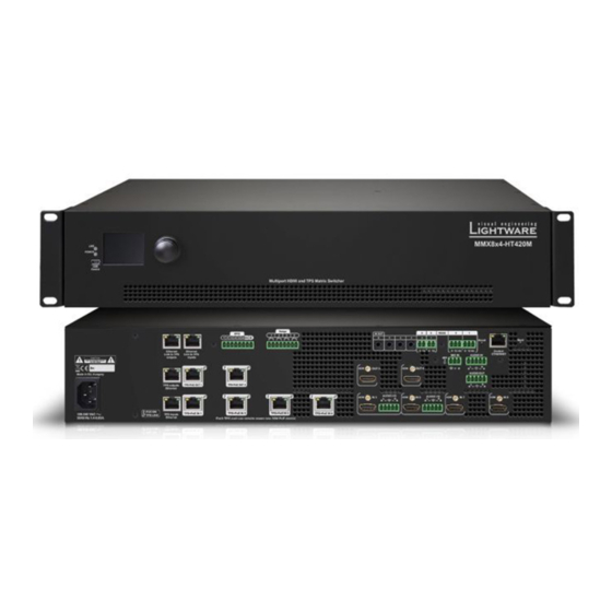
Summary of Contents for Lightware MMX8x4-HT Series
- Page 1 User’s Manual MMX8x4-HT420M MMX8x4-HT400MC MMX8x8-HDMI-4K-A Multiport Matrix Switcher...
- Page 2 MMX8x4-HT series – User's Manual Important Safety Instructions Waste Electrical & Electronic Equipment Common Safety Symbols WEEE Class I apparatus construction. Symbol Description This marking shown on the product or its literature, This equipment must be used with a mains power system with a indicates that it should not be disposed with other protective earth connection.
- Page 3 The following symbols and markings are used in the document: All presented functions refer to the indicated products. The descriptions Lightware Visual Engineering supports green technologies and have been made during testing these functions in accordance with the eco-friend mentality. Thus, this document is made for digital usage...
-
Page 4: Table Of Contents
4.5.2. Autotake Mode ................36 3.3.11. USB Connector ................17 5.11. Event Manager .................58 3.3.12. Relay Connector ................17 5. SOFTWARE CONTROL – LIGHTWARE DEVICE CONTROLLER ...37 5.11.1. The Event Editor................58 3.4. HDMI and TPS Matrix Concept ..........18 5.11.2. Create or Modify an Event............59 5.1. Install and Upgrade ..............37 3.5. TPS Interface ................18... - Page 5 MMX8x4-HT series – User's Manual 5.13. Configuration Cloning (Backup Tab) ........61 6.5. GPIO Settings ................68 7.5.6. Unlock an Input Port ............... 75 5.13.1. Cloning Steps in a Nutshell ............61 6.5.1. Query GPIO State ................68 7.5.7. Lock an Output Port ............... 75 5.13.2. Save the Settings of the Device (Backup) ........
- Page 6 MMX8x4-HT series – User's Manual 7.11. Relay Port Settings ..............92 9. TROUBLESHOOTING ..............108 7.11.1. Set Relay Connection Status ............92 9.1. Use Case Studies ..............108 7.12. GPIO Port Settings ..............92 9.2. How to Speed Up the Troubleshooting Process? ....110 7.12.1. Set the Direction of a GPIO Pin ............ 92 10.
-
Page 7: Introduction
HDMI and TPS (HDBaseT ) interfaces Voice Activated Presenter Focus allows the volume of the voice of Thank you for choosing Lightware’s MMX8x4-HT series device. In the first the speaker to become automatically focused, and the volume of 8 inputs... -
Page 8: Box Contents
1. Introduction MMX8x4-HT series – User's Manual 1.3. Box Contents 1.4. Model Comparison Features and Services MMX8x4-HT400MC MMX8x4-HT420M MMX8x8-HDMI-4K-A 4K / UHD (30Hz RGB 4:4:4 60Hz YCbCr 4:2:0) and 3D capabilities Infrared emitter unit Safety & Warranty Info,... -
Page 9: Features Of The Device
1.5. Features of the Device Remote Power 4K Video The MMX8x4-HT420M matrix is PoE-compatible. The built-in DSP in select Lightware products provides Power over Ethernet or PoE describes a standardized audio mixer services including fader, ducking, equalizer, Supporting uncompressed 4K UHD resolution at 30Hz system which pass electric power along with data on mute, balance and gain. -
Page 10: Typical Application
1. Introduction MMX8x4-HT series – User's Manual 1.6. Typical Application MMX8x4-HT400MC MMX8x8-HDMI-4K-A Reset RS232 AUDIO Reset RS232 AUDIO HDMI HDMI AUDIO HDMI HDMI HDMI HDMI AUDIO AUDIO HDMI HDMI AUDIO HDMI HDMI OUT2 TPS+P AUDIO HDMI HDMI... -
Page 11: Installation
2. Installation MMX8x4-HT series – User's Manual 2.1. Mounting Options -Standard Rack Installation ATTENTION! Always use all the four screws for fixing the rack shelf ears to the rack rail. Choose properly sized screws for mounting. The matrix can be mounted in several ways by the supplied two rack Keep minimum two threads left after the nut screw. -
Page 12: Connecting Steps
Power Infra emitter outlet Button panel Optionally connect the USB cable in order to control the matrix switcher via Lightware Device Laptop Controller software. Projection screen *Only in MMX8x4-HT420M model. Optionally connect the UTP cable (straight or cross, both are supported) in order to control the MMX8x8-HDMI-4K-A model matrix switcher via the Lightware Device Controller software. -
Page 13: Installation Guide For Connecting A Microphone
2 seconds to activate phantom power. These settings can be done from a computer using the Software Control – Lightware Device Lightware Device Controller (LDC) software. The application is available at www.lightware.com, install it on a Port Property Value LW3 command Controller Windows PC or a macOS and connect to the device via LAN, USB, RS-232. -
Page 14: Product Overview
Ý Control Features Ý USB Port USB connector for local control functions (e.g. Lightware Device Controller software). POWER LED indicates that the unit is powered on. POWER LED The unit is powered off or internal voltage problem. blinking slow The unit is on and operates properly. -
Page 15: Rear View
OUT 1 HDMI OUT 2 HDMI OUT 3 HDMI OUT 4 control functions (e.g. Lightware Device Controller software) and message sending Made in EU, Hungary AUDIO OUT are also possible via RS-232 port. See more details in RS-232 Connector section. HDMI... -
Page 16: Electrical Connections
3. Product Overview MMX8x4-HT series – User's Manual 3.3. Electrical Connections You can find more information about the wiring in the Compatible Plug Type Audio Cable Wiring Guide section and about the connection in Phoenix Combicon series (3.5mm pitch, 2-pole), type: MC 1.5/2-ST-3.5. -
Page 17: Control Ethernet Port
Wiring of LAN Cables This variant provides four standard RJ45 connectors for TPS input The MMX8x4-HT420M model contains a 8-pole Lightware recommends the termination of LAN cables on the basis of ports. Not PoE-compatible. Phoenix connector which is used for relay TIA/EIA T 568 A or TIA/EIA T 568 B standards. -
Page 18: Hdmi And Tps Matrix Concept
3. Product Overview MMX8x4-HT series – User's Manual 3.4. HDMI and TPS Matrix Concept 3.5. TPS Interface MMX8x4 series devices are multifunctional audio/video matrix switchers with eight inputs and four outputs. The matrix gives the possibility to route many kinds of signal formats including TPS and other available The matrix gives the possibility to route many kinds of signal formats including TPS and other available interfaces. -
Page 19: Power Over Ethernet (Poe)
3. Product Overview MMX8x4-HT series – User's Manual 3.5.2. Power over Ethernet (PoE) Above settings refer to the matrix. The table below details the system's state with regard to mode selection behavior for all possible combinations for both ends of the link: WARNING! The remote power feature of TPS 95 series extenders is not PoE-compatible. -
Page 20: Video Interface
A/D converter MMX8x8-HDMI-4K-A HDMI HDMI HDMI in The video crosspoint settings can be controlled by any of the following ways: ▪ Using Lightware Device Controller (for more information, see Crosspoint Menu section), Audio AUX analog AUX analog Mixer audio out ▪... -
Page 21: The Autoselect Feature
The table below shows the number of the audio signals and connector dedicated Special Audio Input block with input ports for microphone Lightware Device (LDC) Controller software (see more info about it in types by model. HDMI and TPS Output Port Properties section) or with the LW3 protocol and advanced analog line-in. -
Page 22: Mmx8X4-Ht420M
These properties de- embedder embedder To transmit the audio signal set the appropriate video input and output can be set in Lightware Device Controller (LDC) software or with LW3 in the video crosspoint. For more details, see Crosspoint Operations protocol commands. - Page 23 3. Product Overview MMX8x4-HT series – User's Manual 3.7.4.4. AUX Analog Audio I/O AUX Analog Audio I/O 3.7.4.5. AUX Analog Audio I/O Advanced Analog Audio OUT 3.7.4.6. MIC IN Advanced Analog Audio OUT In MMX8x8-HDMI-4K-A model...
-
Page 24: Control Features
This interface supports any third-party system controller with LW2/ Audio LW3 command protocol. The interface can be used to configure the de-embedder device with Lightware Device Controller and establish the connection to Lightware Device Updater software and perform firmware upgrade. Audio MMX8x4-HT420M... - Page 25 3. Product Overview MMX8x4-HT series – User's Manual Ethernet Interface - Example The concept ROOM 2 ROOM 3 In the room 1. the Matrix reaches the LAN by connecting the Control Ethernet port to the Ethernet switch.
-
Page 26: Infra Interface
Infra Tab section. Step 1. Connect a Lightware device which has IR detector unit (e.g. UMX-TPS-140) with a terminal program. Step 2. Push the proper button of the remote control to scan the IR codes in hex format. Step 3. Remove all the non-hexadecimal characters (e.g. spaces, h characters etc.) from the code. -
Page 27: Serial Interface
3. Product Overview MMX8x4-HT series – User's Manual IR Interface - Example Summary of Serial Ports Local Remote RS-232 TTL serial Control Ethernet IR OUT MAIN MENU > System Settings MMX8x4-HT400MC LIVE Input Ports POWER Output Ports... -
Page 28: Gpio Interface
3. Product Overview MMX8x4-HT series – User's Manual Disconnect Command injection mode TTL Serial This mode is for control the third-party device from the Matrix. In this In this mode, the matrix works as an RS-232–Ethernet bidirectional The 2-pole Phoenix connector can be both infra or serial output. -
Page 29: Relay Interface
Event Manager settings in the Event Manager The matrix contains four relay modules which can be accessed by an section. 8-pole Phoenix connector. The relays can be controlled by Lightware Settings 3.8.6. USB Control Interface protocol commands (LW3) and Event manager actions can be Step 1. -
Page 30: Operation
4. Operation MMX8x4-HT series – User's Manual 4.1. Powering On 4.3. Front Panel LCD Menu Operations Connect the power cord to the AC input connector; the matrix is The front panel has a color LCD that shows the most important immediately powered on. -
Page 31: System Settings Menu
4. Operation MMX8x4-HT series – User's Manual 4.3.1. System Settings Menu 4.3.2. Ports Menu Device Info Submenu PORTS In this submenu you can check basic When entering the menu the available video Network Submenu > I1 DEVICE INFO information about the transmitter unit: input and output ports are listed. -
Page 32: Edid Menu
4. Operation MMX8x4-HT series – User's Manual Video Settings Submenu for Input Ports Volume settings are available in this submenu: Save Submenu HDCP ENABLE SAVE ▪ HDCP Enable (Disabled / Enabled) ▪ MIC INPUT Volume (from -80 to 10) The EDID of a connected sink can be saved to >... -
Page 33: Crosspoint Menu
4. Operation MMX8x4-HT series – User's Manual 4.3.5. Crosspoint Menu 4.4. Front Panel Button Operations 4.4.3. View Crosspoint State Crosspoint settings can be viewed and switched in the front panel The current switching status can be checked on the front panel by... -
Page 34: Switching Operations
In Autotake mode only states of destinations can be viewed. ATTENTION! However, the front panel buttons allow to lock only the output ports, the input ports can also be locked by using Lightware Press and release the required destination button. Now the source... -
Page 35: Control Lock
4. Operation MMX8x4-HT series – User's Manual 4.4.7. Save or Load a Preset Step 3. Press and release Take button. The selected destinations are Loading a Preset in Take Mode now locked. Step 1. Press and release the Load preset button. -
Page 36: Front Panel Operations - Quick Summary
4. Operation MMX8x4-HT series – User's Manual ATTENTION! Preset save action always stores the current Save a Preset Create a Connection configuration for all outputs. Loading a Preset in Autotake Mode MAIN MENU CONTROL C C O O N N T T R R O O L L... -
Page 37: Software Control - Lightware Device Controller
The matrix can be controlled by a computer through the LAN or USB ports using process finished, Only one updateable instance can Different versions can be Lightware Device Controller (LDC). The software can be installed on a Windows button Download Update exist for all users installed for all users PC or macOS. -
Page 38: Device Discovery Window
The Ethernet tab consists of two lists: ▪ Favorite Devices: You can add any Lightware device that is connected via Ethernet and no need to browse all the available devices. Devices can be added by pressing the Add button or marking the desired device by the symbol in the All Devices list. -
Page 39: Crosspoint Menu
5. Software Control – Lightware Device Controller MMX8x4-HT series – User's Manual 5.4. Crosspoint Menu MMX8x8-HDMI-4K-A When LDC finds the hardware, it determines the product type, and the LDC starts with the default page, showing the Crosspoint menu. -
Page 40: Crosspoint Operations
5. Software Control – Lightware Device Controller MMX8x4-HT series – User's Manual 5.4.1. Crosspoint Operations 5.5. Video Tab Available Settings ▪ Port name 5.5.1. TPS Input Port Properties Switching Mute/unmute the port; ▪ To make a connection click on the desired INFO: MMX8x8-HDMI-4K-A model has no TPS port. -
Page 41: Hdmi Input Port Properties
5. Software Control – Lightware Device Controller MMX8x4-HT series – User's Manual 5.5.2. HDMI Input Port Properties Available Settings Deembed to aux audio Port name ▪ Audio de-embedder is able to separate the HDMI video and audio. - Page 42 Check the command of them are displayed on the graphical interface, The MMX8x4-HT series matrix switchers are able to send and receive accepted commands in the documentation of the device. list too (on the left side).
-
Page 43: Hdmi And Tps Output Port Properties
5. Software Control – Lightware Device Controller MMX8x4-HT series – User's Manual 5.5.3. HDMI and TPS Output Port Properties Available Settings Analog audio settings ▪ Port name The displayed configurable settings depends on the chosen audio INFO: MMX8x8-HDMI-4K-A model has no TPS output port. -
Page 44: Diagnostic Tools
5. Software Control – Lightware Device Controller MMX8x4-HT series – User's Manual 5.6. Diagnostic Tools INFO: You can find more details about maximum twisted pair cable distances in the Maximum Extension Distances section. 5.6.1. Cable Diagnostics Table and Chart Views The cable diagnostics is a useful tool to determine any cable related issues in case of TPS connection. -
Page 45: Frame Detector
2 seconds. Frame Detector Window Lightware’s Frame Detector function works like a signal analyzer and makes possible to determine the exact video format that is present on the port, thus helps to identify many problems. E.g. actual timing parameters may differ from the expected and this may cause some displays to drop the picture. -
Page 46: Audio Tab
5. Software Control – Lightware Device Controller MMX8x4-HT series – User's Manual 5.7. Audio Tab 5.7.1. Panorama or Balance Settings 5.7.3. Equalization (EQ) Settings Panorama property is available See the advanced layout to reach all MMX8x4-HT400MC and MMX8x4-HT420M model microphone input settings. -
Page 47: Signal Indicator Chart
5. Software Control – Lightware Device Controller MMX8x4-HT series – User's Manual Equalization (EQ) setting example Signal indicator lights up when the signal level is above: Save a scene Step 1. Do the required configuration in the advanced audio window. -
Page 48: Microphone Input Channel
5. Software Control – Lightware Device Controller MMX8x4-HT series – User's Manual 5.7.7. Microphone Input Channel 5.7.8. Legend of Microphone Input Channel EQ section: The equalizer section is for set the proper rate Channel name Displays the channel name. All the settings below HIGH, HMID, of the different frequencies (high: 12kHz;... - Page 49 5. Software Control – Lightware Device Controller MMX8x4-HT series – User's Manual Channel Presets Save a preset Step 1. Do the required configuration of the channel. Eight memory slots make possible to save the audio properties for ...
-
Page 50: Advanced Analog Input Channel
5. Software Control – Lightware Device Controller MMX8x4-HT series – User's Manual 5.7.9. Advanced Analog Input Channel 5.7.10. Embedded or Analog Input Channel 5.7.11. Legend of Embedded or Advanced Input Channel This settings refers to the advanced analog audio signal. -
Page 51: Advanced Analog Output Channel
5. Software Control – Lightware Device Controller MMX8x4-HT series – User's Manual 5.7.12. Advanced Analog Output Channel 5.7.13. Legend of Advanced Analog Output Channel This settings refers to the balanced analog output port. Channel name Displays the channel name. All the settings below belongs to the channel. -
Page 52: Presets Tab
5. Software Control – Lightware Device Controller MMX8x4-HT series – User's Manual 5.8. Presets Tab Step 2. Select the Presets tab from the Crosspoint menu and choose a target preset slot from Preset 1. .Preset 6. Type the desired Preset name in the indicated text field up to 16 characters. The followings The matrix has six user-programmable presets. -
Page 53: Edid Menu
5. Software Control – Lightware Device Controller MMX8x4-HT series – User's Manual 5.9. EDID Menu 5.9.1. Sources and Destinations The EDID memory consists of four parts: Advanced EDID Management can be accessed by selecting the EDID menu. There are two panels: left one contains Source EDIDs, right one contains Destination places where the EDIDs can be emulated or copied. -
Page 54: Edid Summary Window
EDID file, or uploaded to the User memory. For more details about EDID Editor please visit our selected User memory. website (www.lightware.com) and download the EDID Editor User's Manual. ATTENTION! The imported EDID overwrites the selected memory place even if it is not empty. -
Page 55: Creating An Edid
5.9.5. Creating an EDID 5.10. Control Menu Since above mentioned Advanced EDID Editor needs more complex knowledge about EDID, Lightware The menu gives the opportunity to set the interfaces which can be used to connect or control third party introduced a wizard-like interface for fast and easy EDID creation. With Easy EDID Creator it is possible to devices. -
Page 56: Ethernet
5. Software Control – Lightware Device Controller MMX8x4-HT series – User's Manual The following settings and functions are also available: ATTENTION! If the Ethernet port is set to disabled, this may break the connection with the device. -
Page 57: Gpio Tab
5. Software Control – Lightware Device Controller MMX8x4-HT series – User's Manual 5.10.4. GPIO Tab 5.10.5. Relay Tab INFO: Only MMX8x4-HT420M model has GPIO port. INFO: Only MMX8x4-HT420M model has Relay port. GPIO tab in Control menu in MMX8x4-HT420M model... -
Page 58: Event Manager
5. Software Control – Lightware Device Controller MMX8x4-HT series – User's Manual 5.11. Event Manager 5.11.1. The Event Editor Press the Edit button in the desired Event line to open the Event editor window. The feature means that the device can sense changes on its ports and able to react according to the pre-defined settings. -
Page 59: Create Or Modify An Event
5. Software Control – Lightware Device Controller MMX8x4-HT series – User's Manual 5.11.2. Create or Modify an Event the exact path and set the value of the given property. Step 4. Select the desired Condition and press the Apply button to store the settings. -
Page 60: Clear One Or More Event(S)
5. Software Control – Lightware Device Controller MMX8x4-HT series – User's Manual 5.12. Settings Menu no delay Condition = true Perform the action 5.12.1. Status simple delay Condition = true Delay Perform the action General information is shown on this tab, such as device label, part number, serial number and hardware health, voltage and temperature values. -
Page 61: Network Tab
Backup tab in Settings menu Network tab in Settings menu The configuration cloning of Lightware LW3 devices is a simple method that eliminates the need to repeatedly configure certain devices to have identical (non-factory) settings. If the devices are installed in the same 5.12.3. Backup... -
Page 62: Save The Settings Of The Device (Backup)
5. Software Control – Lightware Device Controller MMX8x4-HT series – User's Manual 5.13.2. Save the Settings of the Device (Backup) 5.13.4. Create and Restore Backups from the Device Memory Step 1. Apply the desired settings in the transmitter (port parameters, crosspoint, etc.) MMX8x4 series matrix is able to store backups in its own memory and can be recalled from there so user Step 2. -
Page 63: Advanced View
5. Software Control – Lightware Device Controller MMX8x4-HT series – User's Manual 5.14. Advanced View Advanced view is the surface for displaying the LW3 protocol tree. Commands and specific parameters (which are not available on the graphical user interface of the LDC) can be run and set by the controlling tools. -
Page 64: Lw2 Programmers' Reference
Input number in 2 digit ASCII format (01, 02, 10, 12 etc.) L W2 Programmers’ Reference <out²> Output number in 2 digit ASCII format (01, 02, 10, 12 etc.) Lightware MMX8x4-HT family can be controlled with external devices which <loc> Location number in 1, 2 or 3 digit ASCII format can communicate according to the extender protocol. -
Page 65: Query Device Label
6. LW2 Programmers’ Reference MMX8x4-HT series – User's Manual 6.2.3. Query Device Label 6.2.8. View Installed Board(s) Description: The device responds its label. Description: Shows the hardware name and revision of the installed boards. Format Example Format Example Command {LABEL=?} →... -
Page 66: Query Health Status
6. LW2 Programmers’ Reference MMX8x4-HT series – User's Manual 6.2.11. Query Health Status 6.3.3. Mute Specified Output Description: Queries health status. The response depends on the frame type. Description: Mute output <out>. The output signal is turned off. -
Page 67: View Connection State On The Output
6. LW2 Programmers’ Reference MMX8x4-HT series – User's Manual ATTENTION! The delay timeout applies for the receiving time of characters. Please note that if LAN 6.3.7. View Connection State on the Output connection is used then the network may cause additional delays. This could result that batch switching Description: Viewing the output’s connection results in different response length, because it depends on the... -
Page 68: Set The Ip Address
6. LW2 Programmers’ Reference MMX8x4-HT series – User's Manual 6.4.3. Set the IP Address 6.4.7. Set the Gateway Address Description: Gateway address can be set as follows. Description: IP address can be set as follows: Format Example Format Example Command {IP_GATEWAY=<gateway_addr>}... -
Page 69: Relay Settings
6. LW2 Programmers’ Reference MMX8x4-HT series – User's Manual 6.6. Relay Settings See in section Command Operation Restart the Matrix Router 6.2.10 {RST} INFO: These commands are available in MMX8x4-HT420M model. Query Health Status 6.2.11 {ST} 6.6.1. Query Relay Connection State Restore Factory Default Settings 6.2.12... -
Page 70: Lw3 Programmers' Reference
(Cr, ‘\r’) and line feed (Lf, ‘\n’) pair. It is organized as a tree structure that provides outstanding flexibility and user-friendly handling with ‘nodes’, ‘properties’ and ‘methods’. The Advanced View of the Lightware Device Controller software is the perfect tool for browsing and learning how the LW3 protocol can be used in practice. -
Page 71: Command Types
7. LW3 Programmers' Reference MMX8x4-HT series – User's Manual 7.2.3. Command Types 7.2.4. Prefix Summary DEFINITION: The prefix is a 2-character long code that describes the type of the response. GET command The following prefixes are defined in the LW3 protocol: The GET command can be used to get the child nodes, properties and methods of a specific node. -
Page 72: Signature
7. LW3 Programmers' Reference MMX8x4-HT series – User's Manual 7.2.7. Signature 7.2.9. Notifications about the Changes of the Properties DEFINITION: The signature is a four-digit-long hexadecimal value that can be optionally placed before When the value of a property is changed and the user is subscribed to the node, which the property belongs every command to keep a command and the corresponding responses together as a group. -
Page 73: System Commands
7. LW3 Programmers' Reference MMX8x4-HT series – User's Manual 7.3. System Commands 7.3.4. Query the Serial Number Example Ý SET /MANAGEMENT/UI.ControlLock=1 7.3.1. Query the Product Name Command and Response Ü pw /MANAGEMENT/UI.ControlLock=1 Ý GET•/.SerialNumber The name of the product is a read-only parameter and cannot be 7.3.7. Identify the Device... -
Page 74: Switching And Crosspoint Settings
7. LW3 Programmers' Reference MMX8x4-HT series – User's Manual 7.4. Switching and Crosspoint Settings 7.5. Video Port Settings 7.4.1. Query the Video Crosspoint State 7.5.1. Mute an Input Port Command and Response Command and Response Ý GET•/MEDIA/VIDEO/XP.DestinationConnectionList Ý CALL•/MEDIA/VIDEO/XP:muteSource(<in>) pr•/MEDIA/VIDEO/XP.DestinationConnectionList=<out1_state>;<out2_state>;<…>;<o5_state>... -
Page 75: Lock An Input Port
7. LW3 Programmers' Reference MMX8x4-HT series – User's Manual 7.5.5. Lock an Input Port 7.5.9. HDCP Setting (Input Port) HDCP capability can be enabled/disabled on the input ports, thus, non-encrypted content can be seen on a Command and Response non-HDCP compliant display. -
Page 76: Query The Status Of Source Port
7. LW3 Programmers' Reference MMX8x4-HT series – User's Manual 7.5.11. Query the Status of Source Port Example and Explanation (M00AA): Command and Response Ý GET•/MEDIA/VIDEO/XP.SourcePortStatus Unlocked, No embedded Ü pr•/MEDIA/VIDEO/XP.SourcePortStatus=<in1_state>;<in2_state>;<…>; <in#_state> Unmuted Reserved Reserved Reserved Reserved No signal... -
Page 77: Query The Status Of Destination Port
7. LW3 Programmers' Reference MMX8x4-HT series – User's Manual 7.5.12. Query the Status of Destination Port DP: the autoselect is Disabled on output 1, output 4, and output 5. EP: the Autoselect is Enabled on output 2 (selected mode is Priority detect). -
Page 78: Query The Input Port Priority
7. LW3 Programmers' Reference MMX8x4-HT series – User's Manual 7.5.15. Query the Input Port Priority Parameters <prio> Priority number from 0 to 31, equal numbers are allowed (31 means that the port will be Command and Response skipped from the priority list). -
Page 79: Sending Cec Commands
7. LW3 Programmers' Reference MMX8x4-HT series – User's Manual 7.5.18. Sending CEC Commands 7.5.18.2. Send CEC Command in Text Format Ý CALL /MEDIA/CEC/<port>:send(<command>) INFO: The hidden first 2 bit of the CEC command is static (always 04), it refers to the logical address of the sender and the addressee. -
Page 80: Poe Enable
7. LW3 Programmers' Reference MMX8x4-HT series – User's Manual 7.5.21. Test Pattern 7.5.18.3. Send CEC Command in Hexadecimal Format Ý CALL /MEDIA/CEC/<port>:sendHex(<hex_code>) The output ports can send a special image towards the sink devices for testing purposes. The setting is available on output ports with the below-listed parameters. -
Page 81: Edid Management
7. LW3 Programmers' Reference MMX8x4-HT series – User's Manual 7.6.2. Set the Emulated EDID 7.5.21.3. Test pattern Command and Response Command and Response SET•/MEDIA/VIDEO/<out>.TpgPattern=<pattern> Ý Ý CALL•/EDID:switch(<source>:<destination>) pw•/MEDIA/VIDEO/<out>.TpgPattern=<pattern> Ü Ü mO•/EDID:switch Parameters Parameters <pattern> GREEN BLUE BLACK WHITE RAMP... -
Page 82: Aux Analog Audio I/O Port Settings
7. LW3 Programmers' Reference MMX8x4-HT series – User's Manual 7.7. AUX Analog Audio I/O Port Settings 7.7.3. AUX Analog Audio Output Settings 7.7.2.2. Volume This command sets the volume in dB scale. 7.7.3.1. Mute INFO: Analog audio input/output setting commands... -
Page 83: Advanced Audio Settings
7. LW3 Programmers' Reference MMX8x4-HT series – User's Manual 7.8. Advanced Audio Settings 7.8.1.3. Set the Volume by Step Value - Volume up INFO: L1 and R1 are near the center, L6 means the maximum left side, R6 means the maximum right side. - Page 84 7. LW3 Programmers' Reference MMX8x4-HT series – User's Manual 7.8.1.8. Switch on the Phantom Power 7.8.1.10. Set the Feedback on Microphone Input For more details about the Lowpass Filter see Legend of Microphone Input Channel section. WARNING! Phantom power supplies the condenser microphone...
-
Page 85: Advanced Analog Audio Input
7. LW3 Programmers' Reference MMX8x4-HT series – User's Manual 7.8.2. Advanced Analog Audio Input Example 7.8.2.6. Query the Gain on the Advanced Analog In Ý CALL /MEDIA/AUDIO/I10:volumeUp() Command and Response INFO: Advanced analog audio input setting commands are available in MMX8x4-HT400MC (for I10 audio port) and MMX8x4-HT420M Ü... -
Page 86: Embedded Audio Input Settings
7. LW3 Programmers' Reference MMX8x4-HT series – User's Manual 7.8.2.9. Set the Highpass Filter on Advanced Analog In Example Example Command and Response Ý SET /MEDIA/AUDIO/I10.PEQ1Gain=-16 Ý GET /MEDIA/AUDIO/I6.SamplingFreq Ü pw /MEDIA/AUDIO/I10.PEQ1Gain=-15.00 Ü pr /MEDIA/AUDIO/I6.SamplingFreq=0 SET•/MEDIA/AUDIO/I10.HPF=<hpf_status> Ý... - Page 87 7. LW3 Programmers' Reference MMX8x4-HT series – User's Manual 7.8.3.5. Set the Volume by Step Value - Volume up INFO: L1 and R1 are near the center, L6 means the maximum left Example side, R6 means the maximum right side.
-
Page 88: Advanced Analog Audio Output
7. LW3 Programmers' Reference MMX8x4-HT series – User's Manual 7.8.4. Advanced Analog Audio Output 7.8.4.3. Set the Volume by Step Value - Volume up 7.8.4.6. Set the Phase Invert on Analog Audio Out This command increases the volume in decibel by one step on the fix... -
Page 89: Audio Presets
7. LW3 Programmers' Reference MMX8x4-HT series – User's Manual 7.8.4.8. Set the Delay on Analog Audio Out Example Command and Response Ý SET /MEDIA/AUDIO/O6.PEQ1Gain=-16.00 Ü pw /MEDIA/AUDIO/O6.PEQ1Gain=-15.00 SET•/MEDIA/AUDIO/O6.Delay=<delay_status> Ý pw•/MEDIA/AUDIO/O6.Delay=<delay_status> For more details, see Equalization (EQ) Settings. -
Page 90: Audio Scenes
7. LW3 Programmers' Reference MMX8x4-HT series – User's Manual 7.8.5.3. Delete a Preset 7.8.6.2. Save a Scene Command and Response Command and Response Ý CALL /PRESETS/MICADDON/<ch>:deletePreset(<index>) Ý CALL /PRESETS/MICADDON/SCENES:saveScene(<index>,I9,I10,I11,O6,<scene_name>) Ü mO /PRESETS/MICADDON/SCENES:saveScene Ü mO /PRESETS/MICADDON/<ch>:deletePreset Parameters Parameters Identifier... -
Page 91: Serial Port Settings
7. LW3 Programmers' Reference MMX8x4-HT series – User's Manual 7.9.2. BAUD Rate Setting 7.9.4. Command Injection Mode 7.8.6.4. Delete a Scene Command and Response Command and Response Command and Response Ý CALL /PRESETS/MICADDON/SCENES:deleteScene(<index>) SET•/MEDIA/UART/<serial_port>.Baudrate=<baudrate> SET•/MEDIA/UART/<serial_port>.CommandInjectionEnable=<ci_stat> Ý Ý Ü mO /PRESETS/MICADDON/SCENES:deleteScene pw•/MEDIA/UART/<serial_port>.Baudrate=<baudrate>... -
Page 92: Ir Port Settings
7. LW3 Programmers' Reference MMX8x4-HT series – User's Manual 7.10. IR Port Settings 7.11. Relay Port Settings 7.12.2. Set the Output Level of a GPIO Pin 7.10.1. Enable the IR Port 7.11.1. Set Relay Connection Status Command and Response SET•/MEDIA/GPIO/<gpio_port>.Output=<value> INFO: This command is available in MMX8x4-HT420M model. -
Page 93: Network Configuration
7. LW3 Programmers' Reference MMX8x4-HT series – User's Manual 7.13. Network Configuration 7.13.4. Set a Static IP Address 7.13.1. Query the Current IP Address Command and Response SET•/MANAGEMENT/NETWORK.StaticIpAddress=<IP_address> Ý Command and Response pw•/MANAGEMENT/NETWORK.StaticIpAddress=<IP_address> Ü Ý GET•/MANAGEMENT/NETWORK.IpAddress pr•/MANAGEMENT/NETWORK.IpAddress=<ip_address> Example Ü... -
Page 94: Sending Message Via The Communication Ports
7. LW3 Programmers' Reference MMX8x4-HT series – User's Manual 7.14. Sending Message via the Communication Ports 7.14.1.3. Sending a TCP Binary Message (HEX-format) The command is for sending a binary message in Hexadecimal format. This method does not allow escaping 7.14.1. Sending Message via TCP Port... -
Page 95: Message Sending Via Rs-232 Serial Port
7. LW3 Programmers' Reference MMX8x4-HT series – User's Manual 7.14.2.2. Sending a UDP Text (ASCII-format) 7.14.3.2. Sending a Text (ASCII-format) via RS-232 The command is for sending a text message in ASCII-format via UDP-protocol. This method does not allow The command is for sending a command message in ASCII-format. -
Page 96: Sending Pronto Hex Codes In Little-Endian Format Via Ir Port
7. LW3 Programmers' Reference MMX8x4-HT series – User's Manual 7.14.5. Sending Pronto Hex Codes in Little-endian Format via IR Port 7.14.6. Sending Pronto Hex Codes in Big-endian Format via IR Port 7.15. System Monitoring Commands For more details about the pronto hex codes see... -
Page 97: Hotplug Detect
The Remote node contains some basic status information about the Ý GET•/MEDIA/VIDEO/<port>.Power5vIn Command and Response Lightware device which is connected to a TPS port of the matrix. Ü pr•/MEDIA/VIDEO/<port>.Power5vIn =<power5v_status> GET•/MEDIA/AUDIO/<advanced_port>.<sign_level><ch> 7.15.6.1. Query the Connection State of the Remote Device Ý... -
Page 98: Lw3 Quick Summary
7. LW3 Programmers' Reference MMX8x4-HT series – User's Manual 7.16. LW3 Quick Summary Video Port Settings Mute an Input Port System Commands Ý CALL•/MEDIA/VIDEO/XP:muteSource(<in>) Query the Product Name Unmute an Input Port Ý GET•/.ProductName Ý CALL•/MEDIA/VIDEO/XP:unmuteSource(<in>) Query the Device Label Mute an Output Port SET•/MANAGEMENT/UID/DeviceLabel=<custom_name>... - Page 99 7. LW3 Programmers' Reference MMX8x4-HT series – User's Manual AUX Analog Audio I/O Port Settings TPS Mode Settings on TPS Ports Audio Mode Setting SET•/REMOTE/<tps_port>.tpsModeSetting=<tps_mode_setting> Ý SET•/MEDIA/AUDIO/<in>.AudioMode=<audio_mode> Sending OSD String Ý AUX Analog Audio Input Settings Ý...
- Page 100 7. LW3 Programmers' Reference MMX8x4-HT series – User's Manual Set the Gain n the Microphone Input Set the Phase Invert on Advanced Analog In SET•/MEDIA/AUDIO/I9.InputGain=<gain_value> SET•/MEDIA/AUDIO/I10.InvertPhase=<invertphase_status> Ý Ý Switch on the Phantom Power Set the Highpass Filter on Advanced Analog In SET•/MEDIA/AUDIO/I9.PhantomPower=<phantom_status>...
- Page 101 7. LW3 Programmers' Reference MMX8x4-HT series – User's Manual Advanced Analog Audio Output Audio Scenes Mute the Analog Audio Out Change the Scene Name SET•/MEDIA/AUDIO/O6.Mute=<mute_status> Ý SET /PRESETS/MICADDON/SCENES/<scene_id>.Name=<scene_name> Ý Set the Volume with Exact Value on Analog Audio Out Save a Scene SET•/MEDIA/AUDIO/O6.Volume=<volume_dB>...
- Page 102 7. LW3 Programmers' Reference MMX8x4-HT series – User's Manual GPIO Port Settings Sending a UDP Text (ASCII-format) Set the Direction of a GPIO Pin Ý CALL•/MEDIA/ETHERNET:udpText(<IP_address>:<port_no>=<text>) SET•/MEDIA/GPIO/<gpio_port>.Direction=<dir> Sending a UDP Binary Message (HEX-format) Ý Set the Output Level of a GPIO Pin Ý...
-
Page 103: Firmware Upgrade
The descriptor is displayed after loading the LFP file in Click on the Check now button. program checks the Lightware Device Updater (LDU) software. To get the latest software and the LDU. for available updates on the Lightware website and shows the firmware pack can be downloaded from www.lightware.com. -
Page 104: Detailed Instructions
8. Firmware Upgrade MMX8x4-HT series – User's Manual ▪ If you do not want to check for updates automatically, uncheck the Check for updates automatically Click on the Matrix button on the main screen. option. Step 1. Select the package. - Page 105 8. Firmware Upgrade MMX8x4-HT series – User's Manual Step 2. Select the device. Firmware Components The components of the installed and update firmware version for the selected devices are listed on the following screen. (Update version will be uploaded to the device.) The next step is to select the desired device(s).
- Page 106 8. Firmware Upgrade MMX8x4-HT series – User's Manual Step 3. Upgrade the device. A warning window will pop up before upgrading the device: ▪ Do not unplug the power cable and the LAN cable while the upgrade is in progress. Click OK to continue.
-
Page 107: Keeping The Configuration Settings
8. Firmware Upgrade MMX8x4-HT series – User's Manual Details button opens a new window where the process is logged – see below. Clicking on the Repeat button starts the process again with the selected device(s). The Open logs button opens the temporary folder where the logs can be found. -
Page 108: Troubleshooting
9. Troubleshooting MMX8x4-HT series – User's Manual 9.1. Use Case Studies Symptom Root cause Action Refer to Video signal Device(s) not powered Check the matrix and the other devices if properly they are properly powered; try to unplug and reconnect them. - Page 109 9. Troubleshooting MMX8x4-HT series – User's Manual Symptom Root cause Action Refer to Symptom Root cause Action Refer to Video signal Audio signal Wrong colorspace The sink expects RGB color spaced Not proper audio mode 5.5.2 was set signal, but receives YCbCr.
-
Page 110: How To Speed Up The Troubleshooting Process
In the case of Event Manager issue the event file and/or backup file from the Device Controller ▪ software. The more of the above information you can give us the better. Please send these information to the Lightware Support Team (support@lightware.com) to speed up the troubleshooting process. -
Page 111: Technologies
(dynamic EDID emulation). information about additional Detailed Timings, audio capabilities, For example, the Lightware device can be set up to emulate a sink speaker allocation and HDMI capabilities. It is important to know that device, which is connected to one of the outputs. -
Page 112: Hdcp Management
Protected CATx cable CATx cable Non-HDCP MMX8x4-HT series disabled in the Lightware device. If HDCP is disabled, the connected content compliant sink matrix source will detect that the sink is not HDCP capable, and turn off The layout is the same as in the previous case: non-HDCP compliant authentication. -
Page 113: Pixel Accurate Reclocking
10. Technologies MMX8x4-HT series – User's Manual 10.3. Pixel Accurate Reclocking Jitter Signal instability in the time domain. The time difference between two Signal reclocking is an essential important procedure in digital signal signal transitions should be a fixed value, but noise and other effects transmission. -
Page 114: Appendix
11. Appendix MMX8x4-HT series – User's Manual 11.1. Specification Embedded audio formats ..2 channel PCM Stereo, 8 channel PCM ..........Dolby TrueHD, DTS-HD Master Audio 7.1 General HDCP compliant...............Yes, HDPC 1.4 Compliance ..................CE Reclocking ............ Pixel Accurate Reclocking EMI/EMC ...... - Page 115 11. Appendix MMX8x4-HT series – User's Manual Control Ethernet Relay Connector type ..............Locking RJ45 Connector type..........8-pole Phoenix connector Ethernet data rate ....10/100Base-T, full duplex with autodetect Number of relays..................4 Power over Ethernet (PoE) ..........Not supported Type..............Normally open contacts...
-
Page 116: Mechanical Drawings
11. Appendix MMX8x4-HT series – User's Manual 11.2. Mechanical Drawings 11.3. Maximum Extension Distances MMX8x4-HT400MC, MMX8x4-HT420M and MMX8x8-HDMI-4K-A matrix switchers have the same size. To specify the accurate extension distances, please also check the documentation of the connected HDBaseT-compatible device. -
Page 117: Factory Default Settings
11. Appendix MMX8x4-HT series – User's Manual 11.4. Factory Default Settings Advanced Audio Settings Advanced audio output (O6) Network Settings Microphone input settings (I9) Parameter Setting/Value Parameter Setting/Value Parameter Setting/Value Mute false IP address 192.168.0.100 Mute false Volume 0.00... -
Page 118: Content Of Backup File
11. Appendix MMX8x4-HT series – User's Manual 11.5. Content of Backup File 11.6. Flowchart of Autoselect Modes Ethernet settings ▪ Port name, Port status (enable / disable) The backup file contains numerous settings and parameters saved from the device. When the file is uploaded to a device, the followings... -
Page 119: Port Numbering
11. Appendix MMX8x4-HT series – User's Manual 11.7. Port Numbering 11.7.1. MMX8x4-HT400MC 11.7.2. MMX8x8-HDMI-4K-A Audio/Video Ports Audio/Video Ports Video port nr. Video port nr. Emulated Audio port nr. Audio port nr. Video port nr. Video port nr. Emulated Audio port nr. -
Page 120: Mmx8X4-Ht420M
11. Appendix MMX8x4-HT series – User's Manual 11.7.3. MMX8x4-HT420M IR Ports GPIO Audio/Video Ports Port nr. Command Port nr. Port nr. Port name Port name (LW2 / LW3) injection port nr. (LW2) (LW3) Video port nr. Video port nr. -
Page 121: Conditions In The Wizard Tab Of The Event Manager
11. Appendix MMX8x4-HT series – User's Manual 11.8. Conditions in the Wizard Tab of the Event Manager GPIO Category Condition General Category HT420M Expression Condition Ports HT400MC HT420M Expression State changes to 'High' P1-P6 Ports Ports State changes to 'Low'... - Page 122 11. Appendix MMX8x4-HT series – User's Manual Audio Category Ethernet Category Action Action Expression Parameters HT400MC Parameters HT420M HT400MC HT420M HDMI-4K-A Expression Parameters Parameters Parameters Set Mic input channel volume on mixer Volume: 0dB to -80dB...
-
Page 123: Factory Edid List
11. Appendix MMX8x4-HT series – User's Manual 11.10. Factory EDID List Mem. Resolution Type Mem. Resolution Type Mem. Resolution Type 1280 x 720 @ 50.00 Hz F108 2560 x 1600 @ 59.86 Hz 640 x 480 @ 60.00 Hz 1280 x 720 @ 60.00 Hz... -
Page 124: Audio Cable Wiring Guide
Symmetric audio is most often referred to as balanced audio, as opposed to asymmetric, which is referred to as unbalanced audio. Lightware products are usually built with 5-pole Phoenix connectors so we would like to help users assembling their own audio cables. -
Page 125: Further Information
1.4. Product failures from six (6) months to the end of the warranty period will either be repaired or replaced at the discretion of Lightware. If Lightware chooses to replace the product then the replacement will be warranted for the remainder of the original unit’s warranty period.
Need help?
Do you have a question about the MMX8x4-HT Series and is the answer not in the manual?
Questions and answers