
Related Manuals for Lightware MMX8x4-HT Series


Summary of Contents for Lightware MMX8x4-HT Series
- Page 1 User’s Manual MMX8x4-HT420M MMX8x4-HT400MC MMX8x8-HDMI-4K-A MMX8x8-HDMI-4K-A-USB20 Multiport Matrix Switcher v1.6 09-07-2020...
- Page 2 MMX8x4-HT series – User's Manual Important Safety Instructions Waste Electrical & Electronic Equipment Common Safety Symbols WEEE Class I apparatus construction. Symbol Description This marking shown on the product or its literature, This equipment must be used with a mains power system with a indicates that it should not be disposed with other protective earth connection.
- Page 3 The following symbols and markings are used in the document: All presented functions refer to the indicated products. The descriptions Lightware Visual Engineering supports green technologies and have been made during testing these functions in accordance with the eco-friend mentality. Thus, this document is made for digital usage...
-
Page 4: Table Of Contents
5.10.2. USB 2.0 Interface ................50 6.10.3. Infra Tab ..................75 3.3.7. Save or Load a Preset ..............25 6.10.4. GPIO Tab ..................76 6. SOFTWARE CONTROL – LIGHTWARE DEVICE CONTROLLER ...52 6.10.5. Relay Tab ..................76 4. INSTALLATION ...................27 6.1. Install and Upgrade ..............53 6.10.6. USB Switch Tab ................77 4.1. Mounting Options -Standard Rack Installation......28... - Page 5 MMX8x4-HT series – User's Manual 6.11.4. Clear One or More Event(s) ............79 7.4.7. View Connection State on the Output ........... 91 8.5. Video Port Settings ..............100 6.11.5. Export and Import Events ............79 7.4.8. View Crosspoint Size ..............91 8.5.1. Mute an Input Port ................ 100 6.12. Settings Menu ................80...
- Page 6 MMX8x4-HT series – User's Manual 8.9.1. Protocol Setting ................120 8.18.3. Query Embedded Audio ............. 127 8.9.2. BAUD Rate Setting ................ 120 8.18.4. Hotplug Detect ................128 8.9.3. Operation Mode Setting ............... 120 8.18.5. Query Audio Indicators ............... 128 8.9.4. Command Injection Mode ............120 8.18.6. Remote ..................
-
Page 7: Introduction
1. Introduction MMX8x4-HT series – User's Manual I ntroduction Thank you for choosing Lightware’s MMX8x4-HT series device. In the first chapter we would like to introduce the device highlighting the most important features in the below listed sections: Description Ý... -
Page 8: Description
1.1.1. Compatible Devices The matrix switchers are compatible with other Lightware TPS devices, matrix boards third-party HDBaseT extenders, displays, but not compatible with the phased out TPS-90 extenders. -
Page 9: Box Contents
1. Introduction MMX8x4-HT series – User's Manual 1.2. Box Contents Infrared emitter LAN straight- Safety and Infrared emitter Phoenix Phoenix Phoenix Phoenix ® ® ® ® Matrix LAN Cross-link, unit Phoenix through ® Warranty Info, IEC Power Cable... -
Page 10: Features Of The Devices
Advanced EDID Management The built-in DSP in select Lightware products provides audio mixer services including fader, The user can emulate any EDID on the inputs independently, read out and store any attached ducking, equalizer, mute, balance and gain. -
Page 11: Mmx8X8-Hdmi-4K-A-Usb20
1. Introduction MMX8x4-HT series – User's Manual 1.5. Optional Accessories Special Audio Input Block for Microphone and Line-in The following not-supplied accessories can be purchased and used with the device; please contact Special Audio Input block with input ports for microphone and line-in. The built-in sound sales@lightware.com. -
Page 12: Typical Application
1. Introduction MMX8x4-HT series – User's Manual 1.6. Typical Application MMX8x8-HDMI-4K-A MMX8x4-HT400MC MMX8x4-HT420M Applied firmware package: v1.2.2b5 | LDC software: v2.2.1... - Page 13 1. Introduction MMX8x4-HT series – User's Manual MMX8x8-HDMI-4K-A-USB20 - Small room application #new MMX8x8-HDMI-4K-A-USB20 - Divisible room application #new Applied firmware package: v1.2.2b5 | LDC software: v2.2.1...
-
Page 14: Product Overview
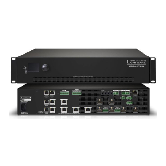
2. Product Overview MMX8x4-HT series – User's Manual Product Overview The following sections are about the physical structure of the device, input/ output ports and connectors: Front View Ý Rear View Ý Applied firmware package: v1.2.2b5 | LDC software: v2.2.1... -
Page 15: Front View
MMX8x4-HT series – User's Manual 2.1. Front View MMX8x4-HT400MC, MMX8x4-HT420M USB Port USB connector for local control functions (e.g. Lightware Device Controller software). POWER LED indicates that the unit is powered on. POWER LED MAIN MENU The unit is powered off or internal voltage problem. -
Page 16: Rear View
The phantom power is turned off. RS-232 port 3-pole Phoenix connectors (2x) for bi-directional RS-232 communication. Local control functions (e.g. Lightware Device Controller software) and message sending are also possible via RS-232 port. See more details in RS-232 Connector section. - Page 17 2. Product Overview MMX8x4-HT series – User's Manual MMX8x8-HDMI-4K-A 8 9 q Ethernet ports The two RJ45 connector for Ethernet (to control the unit or to pass-through). I I R R O O U U T T RS232 They are in the same local network.
-
Page 18: Front Panel Control
3. Front Panel Control MMX8x4-HT series – User's Manual Front Panel Control The following sections are about front panel operation of the device and the status LEDs: Status LEDs Ý Front Panel LCD Menu Operations Ý... -
Page 19: Status Leds
3. Front Panel Control MMX8x4-HT series – User's Manual 3.1. Status LEDs 3.2. Front Panel LCD Menu Operations The front panel has a color LCD that shows the most important settings and parameters structured in a LIVE FRONT menu. -
Page 20: System Settings Menu
3. Front Panel Control MMX8x4-HT series – User's Manual 3.2.1. System Settings Menu Device Info Submenu #firmwareversion In this submenu you can check basic information about the matrix unit: Network Submenu #dhcp #ipaddress #network ▪ Serial number The parameters of the network connection can be set in this submenu. -
Page 21: Ports Menu
3. Front Panel Control MMX8x4-HT series – User's Manual 3.2.2. Ports Menu Video Settings Submenu for Input Ports #hdcp ▪ HDCP Enable (Disabled / Enabled) When entering the menu the available video input and output ports are listed. The icons display information about the port and the video signal (see below table). -
Page 22: Edid Menu
3. Front Panel Control MMX8x4-HT series – User's Manual Audio Settings Submenu for Output Port #balance #volume #mic #microphone Save Submenu INFO: O5 port of MMX8x4-HT400MC and MMX8x4-HT420M models contains The EDID of a connected sink can be saved to the User EDID memory as follows: the audio settings. -
Page 23: Crosspoint Menu
3. Front Panel Control MMX8x4-HT series – User's Manual 3.2.5. Crosspoint Menu 3.3. Front Panel Button Operations Crosspoint settings can be viewed and switched in the front panel LCD menu. DIFFERENCE: Front panel buttons are available in MMX8x8-HDMI-4K-A and MMX8x8-HDMI-4K-A-USB20 models. -
Page 24: View Crosspoint State
Lock an Output Port section). Using Lightware routers it is possible to lock a destination. This feature prevents an accidental switching to the locked destination in case of an important signal. Locking a destination means that no input selection or muting action can be executed on that particular destination. -
Page 25: Control Lock
3. Front Panel Control MMX8x4-HT series – User's Manual 3.3.6. Control Lock Destinations can be independently locked or unlocked. Locking a destination does not affect other destinations. Front panel button operation can be enabled or disabled using Control Lock button, while the remote control is still enabled. - Page 26 3. Front Panel Control MMX8x4-HT series – User's Manual Loading a Preset in Take Mode View Locked Outputs Step 1. Press and release the Load preset button. Step 2. Press and release the desired source (memory address) button (source 1 to 8).
-
Page 27: Installation
4. Installation MMX8x4-HT series – User's Manual Installation Mounting Options -Standard Rack Installation Ý Electrical Connections Ý Powering On Ý Connecting Steps Ý Installation Guide for Connecting a Microphone Ý Applied firmware package: v1.2.2b5 | LDC software: v2.2.1... -
Page 28: Mounting Options -Standard Rack Installation
4. Installation MMX8x4-HT series – User's Manual 4.1. Mounting Options -Standard Rack Installation ATTENTION! Always use all the four screws for fixing the rack shelf ears to the rack rail. Choose properly sized screws for mounting. Keep minimum two threads left after the nut screw. -
Page 29: Electrical Connections
4. Installation MMX8x4-HT series – User's Manual 4.2. Electrical Connections 4.2.4. RS-232 Connector The receiver contains a 3-pole Phoenix connector which is used for RS-232 serial connection. 4.2.1. HDMI Input and Output Ports Pin nr. Signal The matrix switchers are assembled with standard 19-pole HDMI connectors with screw lock for inputs and Ground outputs. -
Page 30: Control Ethernet Port
MMX8x4-HT400MC and MMX8x4-HT400M models have TPS connector. Lightware recommends the termination of LAN cables on the basis of TIA/EIA T 568 A or TIA/EIA T 568 B This variant provides four standard RJ45 connectors for TPS input ports. Not PoE-compatible. -
Page 31: Gpio - General Purpose Input/Output Ports
You can find more information about relay interface in the Relay Interface section. GPIO connector and plug pin assignments 4.2.11. USB Connector Compatible plug type MMX8x4-HT series have standard USB mini-B receptacle. Phoenix ® Combicon series (3.5mm pitch 8-pole), type: MC 1.5/8-ST-3.5. DIFFERENCE: MMX8x8-HDMI-4K-A-USB20 model have USB-A and USB-B connectors. -
Page 32: Connecting Steps
Optionally for audio input: connect the audio source (e.g. media player) to the audio input port by an audio cable. Optionally connect the USB cable in order to control the matrix switcher via Lightware Device Controller software. Optionally connect the UTP cable (straight or cross, both are supported) in order to control the matrix switcher via the Lightware Device Controller software. -
Page 33: Powering On
Optionally connect a serial device (e.g projector) to the 3-pole Phoenix connector to transmit RS-232 RS-232 commands. Optionally connect the USB cable in order to control the matrix switcher via Lightware Device Controller software. Optionally connect the UTP cable (straight or cross, both are supported) in order to control the matrix switcher via the Lightware Device Controller software. -
Page 34: Installation Guide For Connecting A Microphone
2 seconds to activate phantom power. These settings can be done from a computer using the Software Control – Lightware Device Lightware Device Controller (LDC) software. The application is available at www.lightware.com, install it on a Port Property Value LW3 command Controller Windows PC or a macOS and connect to the device via LAN, USB, RS-232. -
Page 35: Device Concept
5. Device Concept MMX8x4-HT series – User's Manual Device Concept MMX8x4 series devices are multifunctional audio/video matrix switchers with eight inputs and four outputs. The matrix gives the possibility to route many kinds of signal formats including TPS and other available interfaces. This chapter is about to present the features and limitations of these interfaces. -
Page 36: Hdmi And Tps Matrix Concept
5. Device Concept MMX8x4-HT series – User's Manual 5.1. HDMI and TPS Matrix Concept Summary of Interfaces - MMX8x4-HT400MC Summary of Interfaces - MMX8x8-HDMI-4K-A Summary of Interfaces - MMX8x8-HDMI-4K-A-USB20 Summary of Interfaces - MMX8x4-HT420M Applied firmware package: v1.2.2b5 | LDC software: v2.2.1... -
Page 37: Tps Interface
5. Device Concept MMX8x4-HT series – User's Manual 5.2. TPS Interface MMX8x4-HT400MC Selected mode on TPS input (RX side) The matrix gives the possibility to route many kinds of signal formats including TPS and other available interfaces. This chapter is about to present the features and limitations of these interfaces. -
Page 38: Power Over Ethernet (Poe)
5. Device Concept MMX8x4-HT series – User's Manual 5.2.2. Power over Ethernet (PoE) WARNING! The remote power feature of TPS 95 series extenders is not PoE-compatible. Thus, TPS 95 series cannot be powered remotely by the MMX8x4 matrix switchers (but the video signal is transmitted to/from the extenders). -
Page 39: Video Interface
MMX8x8-HDMI-4K-A HDMI HDMI The video crosspoint settings can be controlled by any of the following ways: ▪ Using Lightware Device Controller (for more information, see Crosspoint Menu section), ▪ Sending LW2 or LW3 protocol command, (for LW2 commands, see Switch One Input to One... -
Page 40: The Autoselect Feature
5. Device Concept MMX8x4-HT series – User's Manual 5.3.4. The Autoselect Feature The autoselect mode can be set on output ports for each input with Lightware Device (LDC) Controller software (see more info about it in HDMI and TPS Output Port Properties... -
Page 41: Audio Interface
5. Device Concept MMX8x4-HT series – User's Manual 5.4. Audio Interface Advanced audio properties of the audio ports are available in Audio Tab in Lightware Device Controller Software (LDC) or via LW3 control protocol (in LW3 Programmers' Reference section). -
Page 42: Mmx8X8-Hdmi-4K-A And Mmx8X8-Hdmi-4K-A-Usb20
The list below contains the main settings of the audio signal from the source to the destination ports in Input port properties: Set the Audio mode to Embed from aux audio, then additional analog audio input settings different cases. These properties can be set in Lightware Device Controller (LDC) software or with LW3 protocol commands. - Page 43 5. Device Concept MMX8x4-HT series – User's Manual in LDC chapter, for LW3 command see Switching and Crosspoint Settings section. 5.4.4.4. AUX Analog Audio I/O AUX Analog Audio I/O In MMX8x8-HDMI-4K-A and MMX8x8-HDMI-4K-A-USB20 models Port status: Unmute the necessary video input. For more details, see the...
-
Page 44: Ethernet Interface
TPS signal by the converter, as well.) default audio mode in the other ports and this property can not be changed. INFO: The LAN can be enabled or disabled for every single TPS port with Lightware Device Controller (LDC) software or LW3 protocol command. - Page 45 5. Device Concept MMX8x4-HT series – User's Manual Create a link towards the TPS input ports by connecting a patch cable between the two RJ45 connectors Ethernet Interface - Example (Ethernet Link to TPS inputs and TPS inputs Ethernet).
-
Page 46: Infra Interface
Learn IR code Step 1. Connect a Lightware device which has IR detector unit (e.g. UMX-TPS-140) with a terminal program. Step 2. Push the proper button of the remote control to scan the IR codes in hex format. Step 3. Remove all the non-hexadecimal characters (e.g. spaces, h characters etc.) from the code. -
Page 47: Serial Interface
5. Device Concept MMX8x4-HT series – User's Manual 5.7. Serial Interface IR Interface - Example Technical Background Serial data communication can be established via the local RS-232 port (Phoenix connector), TTL serial port (Phoenix connector) and over the TPS lines. The RS-232 ports – which are connected to the microcontroller –... - Page 48 5. Device Concept MMX8x4-HT series – User's Manual Control mode The incoming data from the given port is processed and interpreted by the CPU. The mode allows to control the matrix directly. LW2 or LW3 protocol commands are accepted – depending on the current port setting.
-
Page 49: Gpio Interface
5. Device Concept MMX8x4-HT series – User's Manual The concept Settings Step 1. Create an event in Event manager: when signal is present on Input 5 (I5) then set GPIO pins to low The System controller can send commands (input/output switching, control functions, etc.) to the matrix level for Relay box opening. -
Page 50: Relay Interface
All models can be controlled over front panel USB port (mini B-type connector). This interface supports LW3 can be controlled by Lightware protocol commands (LW3) and Event manager actions can be assigned to protocol. The interface can be used to establish a connection to Lightware Device Controller software. - Page 51 5. Device Concept MMX8x4-HT series – User's Manual Device5VEnable Application of USB - Example This function allows sending 5V power to the device. Most USB devices powered by this 5V, so disable and enable this property is equal with unplug and plug the USB connector.
-
Page 52: Software Control - Lightware Device Controller
Software Control – Lightware Device Controller The matrix can be controlled by a computer through the LAN or USB ports using Lightware Device Controller (LDC). The software can be installed on a Windows PC or macOS. The application can be downloaded from www.lightware.com. -
Page 53: Install And Upgrade
The LDC is connected to a device with the indicated static IP address directly; the Device Discovery window checks the available updates on Lightware’s website and opens the is not displayed. When the port number is not set, the default port is used: 10001 (LW2 protocol). For LW3 update window if the LDC found updates. -
Page 54: Device Discovery Window
The Ethernet tab consists of two lists: ▪ Favorite Devices: You can add any Lightware device that is connected via Ethernet and no need to There are three tabs for the different type of interfaces, select the Ethernet, Serial devices or USB tab. -
Page 55: Crosspoint Menu
5. Software Control – Lightware Device Controller MMX8x4-HT series – User's Manual 6.4. Crosspoint Menu MMX8x8-HDMI-4K-A and MMX8x8-HDMI-4K-A-USB20 When LDC finds the hardware, it determines the product type, and the LDC starts with the default page, showing the Crosspoint menu. #crosspoint #switch... -
Page 56: Crosspoint Operations
5. Software Control – Lightware Device Controller MMX8x4-HT series – User's Manual 6.4.1. Crosspoint Operations 6.5. Video Tab 6.5.1. TPS Input Port Properties Switching To make a connection click on the desired square. If there is no connection DIFFERENCE: MMX8x8-HDMI-4K-A and MMX8x8-HDMI-4K-A-USB20 models have no TPS port. -
Page 57: Hdmi Input Port Properties
5. Software Control – Lightware Device Controller MMX8x4-HT series – User's Manual 6.5.2. HDMI Input Port Properties Available Settings ▪ Port name Click on a port to display its properties; Signal status information and the most important parameters are Mute/unmute the port;... - Page 58 5. Software Control – Lightware Device Controller MMX8x4-HT series – User's Manual Available Settings #hdcp #lock #unlock #mute #unmute #portstatus #tpsmode Deembed to aux audio #diagnostic #framedetector Audio de-embedder is able to separate the HDMI video and audio.
- Page 59 (on the left side). Click on the Send button to execute sending the command. The MMX8x4-HT series matrix switchers are able to send and receive Consumer Electronic Control list (CEC) commands. This feature is for remote control of the source or sink device. CEC is a bi-directional communication via HDMI cable, in this case between the output port of the matrix switcher and the sink.
-
Page 60: Hdmi And Tps Output Port Properties
5. Software Control – Lightware Device Controller MMX8x4-HT series – User's Manual 6.5.3. HDMI and TPS Output Port Properties Available Settings #hdcp #lock #unlock #mute #unmute #portstatus #tpsmode #diagnostic #framedetector #autoselect #nosyncscreen #testpattern DIFFERENCE: MMX8x8-HDMI-4K-A and MMX8x8-HDMI-4K-A-USB20 models have no TPS port. -
Page 61: Diagnostic Tools
5. Software Control – Lightware Device Controller MMX8x4-HT series – User's Manual 6.6. Diagnostic Tools Display This section gives a feedback about the basic information of the connected sink device. 6.6.1. Cable Diagnostics ▪ Display name / Preferred resolution / HDMI capable / HDCP capable /HDCP repeater / Deep Color The cable diagnostics is a useful tool to determine any cable related issues in case of TPS connection. -
Page 62: Framedetector
Table view of cable diagnostics Frame Detector Window Lightware’s Frame Detector function works like a signal analyzer and makes possible to determine the exact video format that is present on the port, thus helps to identify many problems. E.g. actual timing parameters may differ from the expected and this may cause some displays to drop the picture. -
Page 63: Test Pattern Generator - No Sync Screen
5. Software Control – Lightware Device Controller MMX8x4-HT series – User's Manual 6.6.3. Test Pattern Generator - No Sync Screen 6.7. Audio Tab The output ports can send a special image towards the sink devices for testing purposes. -
Page 64: Panorama Or Balance Settings
5. Software Control – Lightware Device Controller MMX8x4-HT series – User's Manual 6.7.3. Equalization (EQ) Settings Basic settings can be seen on the default view: TIPS AND TRICKS: The entire view with full functionality of each channel is available by clicking on the See the advanced layout to reach all adjustable properties. -
Page 65: Signal Indicator Chart
5. Software Control – Lightware Device Controller MMX8x4-HT series – User's Manual 6.7.6. Scenes TIPS AND TRICKS: Adjust the Low, Low-mid, High-mid, High values to 0 is recommended as the first step Scenes of the EQ settings. Pursue apply minimal modification of the original signal. -
Page 66: Microphone Input Channel
5. Software Control – Lightware Device Controller MMX8x4-HT series – User's Manual 6.7.7. Microphone Input Channel 6.7.8. Legend of Microphone Input Channel Channel name Displays the channel name. All the settings below belongs to the channel. Phantom power Keep pressed the button for more then 2 sec to switch on and off the 48V DC. - Page 67 5. Software Control – Lightware Device Controller MMX8x4-HT series – User's Manual Channel Presets Factory MIC presets Eight memory slots make possible to save the audio properties for each channel and reload them quick and Five factory presets are available for microphone input channel. These are specialized for easy.
-
Page 68: Advanced Analog Input Channel
5. Software Control – Lightware Device Controller MMX8x4-HT series – User's Manual 6.7.9. Advanced Analog Input Channel 6.7.10. Legend of Embedded or Advanced Input Channel This settings refers to the advanced analog audio signal. Channel name Displays the channel name. All the settings below belongs to the channel. -
Page 69: Embedded Or Analog Input Channel
5. Software Control – Lightware Device Controller MMX8x4-HT series – User's Manual 6.7.11. Embedded or Analog Input Channel 6.7.12. Legend of Embedded or Advanced Input Channel This settings refers to the chosen audio of the embedded HDMI signal Channel name Displays the channel name. -
Page 70: Advanced Analog Output Channel
5. Software Control – Lightware Device Controller MMX8x4-HT series – User's Manual 6.7.13. Advanced Analog Output Channel 6.7.14. Legend of Advanced Analog Output Channel This settings refers to the balanced analog output port. Channel name Displays the channel name. All the settings below belongs to the channel. -
Page 71: Presets Tab
5. Software Control – Lightware Device Controller MMX8x4-HT series – User's Manual 6.8. Presets Tab Saving a Preset Save Step 1. Arrange the desired crosspoint connections. The matrix has six user-programmable presets. Each preset stores a configuration regarding the crosspoint Step 2. -
Page 72: Edid Menu
5. Software Control – Lightware Device Controller MMX8x4-HT series – User's Manual 6.9.1. Sources and Destinations 6.9. EDID Menu The EDID memory consists of four parts: # edid Advanced EDID Management can be accessed by selecting the EDID menu. There are two panels: left one Factory EDID list shows the pre-programmed EDIDs (F1-F149). -
Page 73: Edid Summary Window
EDID file, or uploaded to the User memory. For more details about EDID Editor please visit our selected User memory. website (www.lightware.com) and download the EDID Editor User's Manual. ATTENTION! The imported EDID overwrites the selected memory place even if it is not empty. -
Page 74: Creating An Edid
6.9.5. Creating an EDID 6.10. Control Menu Since above mentioned Advanced EDID Editor needs more complex knowledge about EDID, Lightware The menu gives the opportunity to set the interfaces which can be used to connect or control third party introduced a wizard-like interface for fast and easy EDID creation. With Easy EDID Creator it is possible to devices. -
Page 75: Ethernet
5. Software Control – Lightware Device Controller MMX8x4-HT series – User's Manual 6.10.3. Infra Tab ▪ Parity: None, Odd, or Even; Stop bits: 1, 1.5, or 2; ▪ ATTENTION! The device has no built-in Infrared transmitter. For the complete usage attach an IR emitter Command injection port number;... -
Page 76: Gpio Tab
5. Software Control – Lightware Device Controller MMX8x4-HT series – User's Manual 6.10.4. GPIO Tab 6.10.5. Relay Tab DIFFERENCE: MMX8x4-HT420M and MMX8x8-HDMI-4K-A-USB20 models have GPIO port. INFO: Only MMX8x4-HT420M model has Relay port. GPIO tab in Control menu in MMX8x4-HT420M model... -
Page 77: Usb Switch Tab
5. Software Control – Lightware Device Controller MMX8x4-HT series – User's Manual 6.10.6. USB Switch Tab 6.11. Event Manager DIFFERENCE: Only MMX8x8-HDMI-4K-A-USB20 model has this Tab. #new The feature means that the device can sense changes on its ports and able to react according to the pre-defined settings. -
Page 78: The Event Editor
5. Software Control – Lightware Device Controller MMX8x4-HT series – User's Manual 6.11.1. The Event Editor 6.11.2. Create or Modify an Event Press the Edit button in the desired Event line to open the Event editor window. #eventmanager... -
Page 79: Special Tools And Accessories
5. Software Control – Lightware Device Controller MMX8x4-HT series – User's Manual 6.11.3. Special Tools and Accessories no delay Condition = true Perform the action The Name of the Event simple delay Condition = true Delay Perform the action The name of a port can be changed by typing the new name and clicking the Set button. -
Page 80: Settings Menu
5. Software Control – Lightware Device Controller MMX8x4-HT series – User's Manual 6.12. Settings Menu 6.12.2. Network Tab Network-related settings are available on the tab. #dhcp #ipaddress #network 6.12.1. Status General information is shown on this tab, such as device label, part number, serial number and hardware health, voltage and temperature values. -
Page 81: Configuration Cloning (Backup Tab)
ATTENTION! The cloning is successful when the backup file is downloaded from the same type of source device as the destination device. The configuration cloning of Lightware LW3 devices is a simple method that eliminates the need to repeatedly The Restoring Process configure certain devices to have identical (non-factory) settings. -
Page 82: Create And Restore Backups From The Device Memory
5. Software Control – Lightware Device Controller MMX8x4-HT series – User's Manual 6.13.4. Create and Restore Backups from the Device Memory 6.14. The Built-in Miniweb MMX8x4 series matrix is able to store backups in its own memory and can be recalled from there so user DEFINITION: The miniweb is a dedicated location in the memory where an HTML file can be uploaded to. -
Page 83: Opening The Miniweb
5. Software Control – Lightware Device Controller MMX8x4-HT series – User's Manual 6.14.1. Opening the Miniweb 6.14.2. The Default Status Page The Miniweb is available by: If there is no control page uploaded, the default status page will be displayed (which is also available by opening the <IP_address>/status.html address). - Page 84 5. Software Control – Lightware Device Controller MMX8x4-HT series – User's Manual Customized HTML The default control page can be replaced in the LDC; navigate to the Settings/Status page. Custom HTML file can be uploaded by pressing the Choose file button. Pay attention to the size of the HTML file. Only one file is allowed and the maximum file size is 100 KB.
-
Page 85: Advanced View
5. Software Control – Lightware Device Controller MMX8x4-HT series – User's Manual 6.15. Advanced View Advanced view is the surface for displaying the LW3 protocol tree. Commands and specific parameters (which are not available on the graphical user interface of the LDC) can be run and set by the controlling tools. -
Page 86: Lw2 Programmers' Reference
7. LW2 Programmers’ Reference MMX8x4-HT series – User's Manual L W2 Programmers’ Reference Lightware MMX8x4-HT family can be controlled with external devices which can communicate according to the extender protocol. The supported LW2 commands are described in this chapter. Protocol Description Ý... -
Page 87: Protocol Description
MMX8x4-HT series – User's Manual 7.1. Protocol Description 7.2. Instructions for the Terminal Application Usage The protocol description hereinafter stands for Lightware protocol. The commands can be sent to the device Terminal Application in RAW format via the TCP/IP port no. 10001. -
Page 88: General Lw2 Commands
7. LW2 Programmers’ Reference MMX8x4-HT series – User's Manual 7.3. General LW2 Commands Example {P_?} 7.3.1. View Product Type (CURRENT PROTOCOL = #1) The device responds its name. The device communicates with LW2 protocol. Command and Response 7.3.5. View Firmware Version of the CPU... -
Page 89: View Installed Board(S)
7. LW2 Programmers’ Reference MMX8x4-HT series – User's Manual 7.3.8. View Installed Board(s) (SL END) The device has one control panel. Shows the hardware name and revision of the installed card. #firmwareversion Command and Response 7.3.10. Restart the Matrix Router ... -
Page 90: Port And Crosspoint Settings
7. LW2 Programmers’ Reference MMX8x4-HT series – User's Manual 7.4. Port and Crosspoint Settings 7.4.2. Switch One Input to All Output Switch input <in> to all outputs. 7.4.1. Switch One Input to One Output Command and Response Switching an input <in>... -
Page 91: Lock The Output
7. LW2 Programmers’ Reference MMX8x4-HT series – User's Manual 7.4.5. Lock the Output State letters Locking an output port. Output’s state cannot be changed until unlocking. Letter State Example Command and Response Output is locked Output is muted ... -
Page 92: Batch Switch Outputs
7. LW2 Programmers’ Reference MMX8x4-HT series – User's Manual 7.4.9. Batch Switch Outputs <ip_addr> IP address (four decimal octets separated by dots) The device is capable of switching multiple outputs exactly at the same time. To do this, the normal switch <subnet_mask>... -
Page 93: Set The Gateway Address
7. LW2 Programmers’ Reference MMX8x4-HT series – User's Manual 7.5.4. Set the Gateway Address Parameters Gateway address can be set as follows. Identifier Parameter description Parameter values Command and Response <direction> Direction of the signal I: input ... -
Page 94: Lw2 Commands - Quick Summary
7. LW2 Programmers’ Reference MMX8x4-HT series – User's Manual 7.8. LW2 Commands – Quick Summary GPIO Settings See in section Command Operation General LW2 Commands Set GPIO State 7.6.1 {GPIO<port_nr>=<direction>;<output_level>} Operation See in section Command View Product Type 7.3.1... -
Page 95: Lw3 Programmers' Reference
8. LW3 Programmers' Reference MMX8x4-HT series – User's Manual L W3 Programmers' Reference The device can be controlled through Lightware 3 (LW3) protocol commands to ensure the compatibility with other Lightware products. The supported LW3 commands are described in this chapter. Overview Ý... -
Page 96: Overview
‘nodes’, ‘properties’ and ‘methods’. The Ý GET /.SerialNumber Advanced View of the Lightware Device Controller software is the perfect tool for browsing and learning how the LW3 protocol can be used in practice. -
Page 97: Prefix Summary
8. LW3 Programmers' Reference MMX8x4-HT series – User's Manual 8.2.4. Prefix Summary 8.2.7. Signature DEFINITION: The prefix is a 2-character long code that describes the type of the response. DEFINITION: The signature is a four-digit-long hexadecimal value that can be optionally placed before every command to keep a command and the corresponding responses together as a group. -
Page 98: Notifications About The Changes Of The Properties
8. LW3 Programmers' Reference MMX8x4-HT series – User's Manual 8.2.9. Notifications about the Changes of the Properties 8.3. System Commands When the value of a property is changed and the user is subscribed to the node, which the property belongs 8.3.1. Query the Product Name... -
Page 99: Query The Serial Number
8. LW3 Programmers' Reference MMX8x4-HT series – User's Manual 8.3.4. Query the Serial Number 8.3.7. Identify the Device Calling the method results Device identified! message on the LCD screen. The feature helps to identify the Command and Response device itself in the rack shelf. -
Page 100: Switching And Crosspoint Settings
8. LW3 Programmers' Reference MMX8x4-HT series – User's Manual 8.4. Switching and Crosspoint Settings 8.5. Video Port Settings 8.4.1. Query the Video Crosspoint State 8.5.1. Mute an Input Port Command and Response Command and Response #mute Ý GET•/MEDIA/VIDEO/XP.DestinationConnectionList Ý CALL•/MEDIA/VIDEO/XP:muteSource(<in>) pr•/MEDIA/VIDEO/XP.DestinationConnectionList=<out1_state>;<out2_state>;<…>;<o5_state>... -
Page 101: Lock An Input Port
8. LW3 Programmers' Reference MMX8x4-HT series – User's Manual 8.5.5. Lock an Input Port 8.5.9. HDCP Setting (Input Port) HDCP capability can be enabled/disabled on the input ports, thus, non-encrypted content can be seen on a Command and Response #lock non-HDCP compliant display. -
Page 102: Query The Status Of Source Port
8. LW3 Programmers' Reference MMX8x4-HT series – User's Manual 8.5.11. Query the Status of Source Port Example and Explanation (M00AA): Command and Response #portstatus Ý GET•/MEDIA/VIDEO/XP.SourcePortStatus Unlocked, No embedded Ü pr•/MEDIA/VIDEO/XP.SourcePortStatus=<in1_state>;<in2_state>;<…>; <in#_state> Unmuted Reserved Reserved Reserved Reserved... -
Page 103: Query The Status Of Destination Port
8. LW3 Programmers' Reference MMX8x4-HT series – User's Manual 8.5.12. Query the Status of Destination Port INFO: Output 5 in MMX8x4-HT400MC and MMX8x4-HT420M models means the advanced analog audio output. 8.5.14. Change the Autoselect Mode Command and Response Ý... -
Page 104: Changing The Input Port Priority
8. LW3 Programmers' Reference MMX8x4-HT series – User's Manual In the above example, the Input 8 has the highest priority and Input 7 has the lowest priority on O1. On O2 O3, O4 Parameters and O5 ports the setting is the opposite. -
Page 105: Send Cec Command In Text Format
8. LW3 Programmers' Reference MMX8x4-HT series – User's Manual Example 8.5.19.1. Send CEC Command in Hexadecimal Format Ý SET /MEDIA/CEC/I1.OsdString=Lightware Ý CALL /MEDIA/CEC/<port>:sendHex(<hex_code>) Ü pw /MEDIA/CEC/I1.OsdString=Lightware Ü mO /MEDIA/CEC/<port>:sendHex Ý CALL /MEDIA/CEC/I1:send(set_osd) Parameters Ü mO /MEDIA/CEC/I1:send <hex_code>... -
Page 106: Test Pattern
8. LW3 Programmers' Reference MMX8x4-HT series – User's Manual 8.5.22. Test Pattern 8.5.22.3. Test pattern Command and Response The output ports can send a special image towards the sink devices for testing purposes. The setting is available on output ports with the below-listed parameters. -
Page 107: Set The Emulated Edid
8. LW3 Programmers' Reference MMX8x4-HT series – User's Manual 8.6.2. Set the Emulated EDID 8.7. AUX Analog Audio I/O Port Settings Command and Response #edid INFO: Analog audio input/output setting commands are available in MMX8x4-HT420M model (I5 and I6 audio ports) and MMX8x8-HDMI-4K-A model (I2, I4, I6 and I8 audio ports). -
Page 108: Aux Analog Audio Output Settings
8. LW3 Programmers' Reference MMX8x4-HT series – User's Manual 8.7.3. AUX Analog Audio Output Settings Parameters <volume_dB> Volume can be set between -48.18dB and 0.00dB. 8.7.3.1. Mute Example Command and Response #mute #analogaudio Ý SET /MEDIA/AUDIO/I6/ADCVOLUME.VolumedB=-1 SET•/MEDIA/AUDIO/<in>.DACVOLUME.Mute=<mute_status> Ý Ü pw /MEDIA/AUDIO/I6/ADCVOLUME.VolumedB=-1 pw•/MEDIA/AUDIO/<in>.DACVOLUME.Mute=<mute_status>... -
Page 109: Advanced Audio Settings
8. LW3 Programmers' Reference MMX8x4-HT series – User's Manual 8.8. Advanced Audio Settings Example Ý CALL /MEDIA/AUDIO/I9:volumeUp() INFO: Advanced audio setting commands are available in MMX8x4-HT400MC and MMX8x4-HT420M models. Ü mO /MEDIA/AUDIO/I9:volumeUp 8.8.1. Microphone Input Settings 8.8.1.4. Set the Volume by Step Value - Volume down... - Page 110 8. LW3 Programmers' Reference MMX8x4-HT series – User's Manual 8.8.1.6. Query the Gain on the Microphone Input 8.8.1.9. Set the Phase Inverter on Microphone Input Command and Response Command and Response Ý GET•/MEDIA/AUDIO/I9.InputGain SET•/MEDIA/AUDIO/I9.InvertPhase=<invertphase_status> Ý pw•/MEDIA/AUDIO/I9.InputGain=<gain_value> pw•/MEDIA/AUDIO/I9.InvertPhase=<invertphase_status> Ü...
-
Page 111: Advanced Analog Audio Input
8. LW3 Programmers' Reference MMX8x4-HT series – User's Manual 8.8.1.12. Set the Lowpass Filter on Microphone Input 8.8.1.14. Load Factory Mic Preset Command and Response Command and Response SET•/MEDIA/AUDIO/I9.MicPreset=<preset_nr> SET•/MEDIA/AUDIO/I9.LPF=<lpf_status> Ý Ý Ü pw•/MEDIA/AUDIO/I9.MicPreset =<preset_nr> pw•/MEDIA/AUDIO/I9.LPF=<lpf_status> Ü Parameters... - Page 112 8. LW3 Programmers' Reference MMX8x4-HT series – User's Manual 8.8.2.2. Set the Volume with Exact Value on Advanced Analog In Parameters This command sets the volume in dB. #volume #analogaudio Identifier Parameter description Parameter values <bal_set> Balance setting R1-R6: Right channel, value can be set between 1 and 6.
- Page 113 8. LW3 Programmers' Reference MMX8x4-HT series – User's Manual 8.8.2.7. Set the Gain on the Advanced Analog In 8.8.2.10. Set the Lowpass Filter on Advanced Analog In Command and Response Command and Response SET•/MEDIA/AUDIO/I10.LPF=<lpf_status> SET•/MEDIA/AUDIO/I10.InputGain=<gain_value> Ý Ý pw•/MEDIA/AUDIO/I10.LPF=<lpf_status>...
-
Page 114: Embedded Audio Input Settings
8. LW3 Programmers' Reference MMX8x4-HT series – User's Manual 8.8.3. Embedded Audio Input Settings 8.8.3.3. Mute the Emb. Audio In Command and Response #mute INFO: Embedded audio input setting commands are available in MMX8x4-HT400MC and MMX8x4-HT420M model. The settings refer to the chosen embedded audio channel in the audio mixer. - Page 115 8. LW3 Programmers' Reference MMX8x4-HT series – User's Manual 8.8.3.6. Set the Volume by Step Value - Volume down Example This command decreases the volume in dB by one step on the fix value list (see the value list in the Set the Ý...
-
Page 116: Advanced Analog Audio Output
8. LW3 Programmers' Reference MMX8x4-HT series – User's Manual 8.8.4. Advanced Analog Audio Output 8.8.3.11. Set the Lowpass Filter on the Emb. Audio In Command and Response INFO: Advanced analog audio output setting commands are available in MMX8x4-HT400MC and MMX8x4- HT420M model. - Page 117 8. LW3 Programmers' Reference MMX8x4-HT series – User's Manual 8.8.4.3. Set the Volume by Step Value - Volume up 8.8.4.6. Set the Phase Invert on Analog Audio Out This command increases the volume in decibel by one step on the fix value list (see the list in the previous Command and Response section).
-
Page 118: Audio Presets
8. LW3 Programmers' Reference MMX8x4-HT series – User's Manual 8.8.5. Audio Presets 8.8.4.9. Set the Delay Time on Analog Audio Out Command and Response 8.8.5.1. Save a Preset SET•/MEDIA/AUDIO/O6.Delay=<delay_time> Command and Response Ý pw•/MEDIA/AUDIO/O6.Delay=<delay_time> Ü Ý CALL /PRESETS/MICADDON/<ch>:savePreset(<index>,<target_node>,<name>) Parameters Ü... -
Page 119: Delete A Preset
8. LW3 Programmers' Reference MMX8x4-HT series – User's Manual 8.8.6. Delete a Preset INFO: I9,I10,I11,O6 are the port numbers of the audio channals which values are saved into a scene. So these port numbers are always the same. -
Page 120: Serial Port Configuration
8. LW3 Programmers' Reference MMX8x4-HT series – User's Manual 8.9. Serial Port Configuration 8.9.3. Operation Mode Setting ATTENTION! MMX8x4 series handles many serial ports. The following parameters can be set individually Command and Response on each port; the exact port numbering is listed in Port Numbering section. -
Page 121: Query The Rs-232 Command Injection Port Number
8. LW3 Programmers' Reference MMX8x4-HT series – User's Manual 8.10.3. Sending a Binary Message (HEX-format) via RS-232 ATTENTION! Do not forget to set the TCP/IP port setting which is individual for each RS-232 port and stored in /MEDIA/UART/<serial_port>.CommandInjectionPort parameter. -
Page 122: Query The Ir Command Injection Port Number
8. LW3 Programmers' Reference MMX8x4-HT series – User's Manual 8.11.2. Query the IR Command Injection Port Number 8.12.2. Sending Pronto Hex Codes in Big-endian Format via IR Port Command and Response For more details about the pronto hex codes see Getting IR codes section. -
Page 123: Relay Port Configuration
8. LW3 Programmers' Reference MMX8x4-HT series – User's Manual 8.13. Relay Port Configuration Parameters Identifier Parameter description Parameter values 8.13.1. Set Relay Connection Status <gpio_port> GPIO port number P1-P6 INFO: This command is available in MMX8x4-HT420M model. <value>... -
Page 124: Power Switch Delay
8. LW3 Programmers' Reference MMX8x4-HT series – User's Manual 8.15.2. Power Switch Delay 8.15.4. Device 5V Enable Command and Response #usb Command and Response SET•MEDIA/USB/USBSWITCH.DelayedSwitch=<delay_status> SET•/MEDIA/USB/USBSWITCH.<Device5vEnable>=<enable> Ý Ý pw•MEDIA/USB/USBSWITCH.DelayedSwitch=<delay_status> pw•/MEDIA/USB/USBSWITCH.<Device5vEnable>=<enable> Ü Ü Parameters Parameters Identifier Parameter description Parameter values... -
Page 125: Ethernet Configuration
8. LW3 Programmers' Reference MMX8x4-HT series – User's Manual 8.16. Ethernet Configuration 8.16.4. Set a Static IP Address 8.16.1. Query the Current IP Address Command and Response SET•/MANAGEMENT/NETWORK.StaticIpAddress=<IP_address> Ý Command and Response #dhcp #ipaddress #network pw•/MANAGEMENT/NETWORK.StaticIpAddress=<IP_address> Ü Ý GET•/MANAGEMENT/NETWORK.IpAddress pr•/MANAGEMENT/NETWORK.IpAddress=<ip_address>... -
Page 126: Ethernet Message Sending
8. LW3 Programmers' Reference MMX8x4-HT series – User's Manual 8.17. Ethernet Message Sending 8.17.1.3. Sending a TCP Binary Message (HEX-format) The command is for sending a binary message in Hexadecimal format. This method does not allow escaping 8.17.1. Sending Message via TCP Port or inserting control characters. -
Page 127: System Monitoring Commands
8. LW3 Programmers' Reference MMX8x4-HT series – User's Manual 8.18. System Monitoring Commands 8.17.2.2. Sending a UDP Text (ASCII-format) The command is for sending a text message in ASCII-format via UDP-protocol. This method does not allow 8.18.1. Query Video Signal Presence escaping or inserting control characters. -
Page 128: Hotplug Detect
8. LW3 Programmers' Reference MMX8x4-HT series – User's Manual 8.18.4. Hotplug Detect It gives a feedback about the actual level of the advanced analog input, embedded audio input and the advanced audio output signal. For more details see Panorama or Balance Settings section. -
Page 129: Remote
8.18.6. Remote INFO: These commands are available in MMX8x4-HT400MC and MMX8x4-HT420M models. The Remote node contains some basic status information about the Lightware device which is connected to a TPS port of the matrix. 8.18.6.1. Query the Connection State of the Remote Device This property indicates if the remote device connected or not. -
Page 130: Lw3 Quick Summary
8. LW3 Programmers' Reference MMX8x4-HT series – User's Manual 8.19. LW3 Quick Summary Mute an Output Port Ý CALL•/MEDIA/VIDEO/XP:muteDestination(<out>) System Commands Unmute an Output Port Query the Product Name Ý CALL•/MEDIA/VIDEO/XP:unmuteDestination(<out>) Ý GET•/.ProductName Lock an Input Port Query the Device Label Ý... - Page 131 8. LW3 Programmers' Reference MMX8x4-HT series – User's Manual Query the Emulated EDIDs Set the Panorama on the Microphone Input Ý GET•/EDID.EdidStatus SET•/MEDIA/AUDIO/I9.Panorama=<pan_set> Ý Set the Emulated EDID Query the Gain on the Microphone Input Ý CALL•/EDID:switch(<source>:<destination>) Ý...
- Page 132 8. LW3 Programmers' Reference MMX8x4-HT series – User's Manual Set the Gain on the Advanced Analog In Signal Type Settings (Output Ports) SET•/MEDIA/AUDIO/I10.InputGain=<gain_value> SET•/MEDIA/VIDEO/<out>.HdmiModeSetting=<signal_type> Ý Ý Set the Phase Invert on Advanced Analog In Test pattern generator mode setting SET•/MEDIA/AUDIO/I10.InvertPhase=<invertphase_status>...
- Page 133 8. LW3 Programmers' Reference MMX8x4-HT series – User's Manual Set the Delay on Analog Audio Out Serial Port Messaging SET•/MEDIA/AUDIO/O6.Delay=<delay_status> Sending a Message (ASCII-format) via RS-232 Ý Set the Delay Time on Analog Audio Out Ý CALL•/MEDIA/UART/P1:sendMessage(<message>) SET•/MEDIA/AUDIO/O6.Delay=<delay_time>...
- Page 134 8. LW3 Programmers' Reference MMX8x4-HT series – User's Manual USB Port Settings Sending a TCP Binary Message (HEX-format) USB Host Select Ý CALL•/MEDIA/ETHERNET.tcpBinary(<IP_address>:<port_no>=<HEX_message>) Sending UDP Message (ASCII-format) SET•/MEDIA/USB/USBSWITCH.HostSelect=<USB_host> Ý Power Switch Delay Ý CALL•/MEDIA/ETHERNET:udpMessage(<IP_address>:<port_no>=<message>) Sending a UDP Text (ASCII-format) SET•MEDIA/USB/USBSWITCH.DelayedSwitch=<delay_status>...
-
Page 135: Firmware Upgrade
This chapter is meant to help customers perform firmware upgrades on our products by giving a few tips on how to start and by explaining the features of the Lightware Device Updater v2 (LDU2) software. To get the latest software and firmware pack can be downloaded from www.lightware.com. -
Page 136: Introduction
9.2. Preparation One updateable instance Many different versions can be Most Lightware devices can be controlled over more interfaces (e.g. Ethernet, USB, RS-232). But the firmware may exist for all users installed for all users can be upgraded usually over one dedicated interface, which is the Ethernet in most cases. - Page 137 When the discovery has completed, the devices available on the network are listed in the application. SEARCH FOR DEVICES appears. Press the Search for devices button to start finding the Lightware devices: If you start the software by double-clicking on the LFP2 file, the firmware will be loaded. Press the Search for devices button;...
-
Page 138: The Upgrading Steps
In the case of factory reset, you can save the settings of the device in the Lightware Device Controller software and restore it later. The following flow chart demonstrates how this function works in the background. -
Page 139: If The Upgrade Is Not Successful
If an upgrade is not successful, the Export log button becomes red. If you press the button, you can ▪ download the log file as a ZIP package which can be sent to Lightware Support if needed. The log files contain useful information about the circumstances to find the root cause. -
Page 140: Troubleshooting
10. Troubleshooting MMX8x4-HT series – User's Manual Troubleshooting Usually, if the system seems not to transport the signal as expected, the best strategy for troubleshooting is to check signal integrity through the whole signal chain starting from source side and moving forward to receiver end. -
Page 141: Use Case Studies
10. Troubleshooting MMX8x4-HT series – User's Manual 10.1. Use Case Studies Symptom Root cause Action Refer to Video signal Symptom Root cause Action Refer to Wrong colorspace The sink expects RGB color spaced Video signal was set signal, but receives YCbCr. - Page 142 10. Troubleshooting MMX8x4-HT series – User's Manual Symptom Root cause Action Refer to Symptom Root cause Action Refer to Ethernet Audio signal IP address conflict Change the IP address to a not reserved Not proper audio mode 6.5.2...
-
Page 143: How To Speed Up The Troubleshooting Process
In the case of Event Manager issue the event file and/or backup file from the Device Controller ▪ software. The more of the above information you can give us the better. Please send these information to the Lightware Support Team (support@lightware.com) to speed up the troubleshooting process. Applied firmware package: v1.2.2b5 | LDC software: v2.2.1... -
Page 144: Technologies
11. Technologies MMX8x4-HT series – User's Manual Technologies The following sections contain descriptions and useful technical information how the devices work in the background. The content is based on experiences and cases we met in the practice. These sections help to understand features... -
Page 145: Edid Management
(static EDID emulation), or from the last attached monitor’s memory (dynamic EDID emulation). For example, the Lightware device can be set up to emulate a sink device, which is connected to one of the outputs. In Most DVI computer displays have 128-byte long EDID structure. However, Digital Televisions and HDMI... -
Page 146: Hdcp Management
To avoid unnecessary HDCP encryption, Lightware introduced the HDCP enabling/disabling function: the HDCP capability can be disabled in the Lightware device. If HDCP is disabled, the connected source will detect that the sink is not HDCP capable, and turn off authentication. -
Page 147: Pixel Accurate Reclocking
Without reclocking, sparkles, noise, and jaggies appear on the image. Lightware’s sophisticated Pixel Accurate Reclocking technology fixes more problems than general TMDS reclocking. It removes not only intra-pair skew but inter-pair skew as well. The Pixel Accurate Reclocking... -
Page 148: Appendix
12. Appendix MMX8x4-HT series – User's Manual Appendix Specification Ý Mechanical Drawings Ý Maximum Extension Distances Ý Factory Default Settings Ý Content of Backup File Ý Flowchart of Autoselect Modes Ý Port Numbering Ý Conditions in the Wizard Tab of the Event Manager Ý... -
Page 149: Specification
12. Appendix MMX8x4-HT series – User's Manual 12.1. Specification HDMI Input/Output Ports ..........Dolby TrueHD, DTS-HD Master Audio 7.1 Connector type ........19-pole HDMI Type A receptacle * All standard VESA, CEA and other custom resolutions up to 300MHz General (HDMI1.4) are supported. - Page 150 12. Appendix MMX8x4-HT series – User's Manual Advanced analog audio input port GPIO Connector type ..........5-pole Phoenix connector Connector type ..........8-pole Phoenix connector Input signal ..........Balanced or unbalanced audio Number of configurable pins ..............6 Gain ..................
-
Page 151: Mechanical Drawings
12. Appendix MMX8x4-HT series – User's Manual 12.2. Mechanical Drawings 12.3. Maximum Extension Distances All models have the same size. To specify the accurate extension distances, please also check the documentation of the connected HDBaseT-compatible device. Dimensions are in mm. -
Page 152: Factory Default Settings
12. Appendix MMX8x4-HT series – User's Manual 12.4. Factory Default Settings Advanced Audio Settings Advanced audio output (O6) Network Settings Microphone input settings (I9) Parameter Setting/Value Parameter Setting/Value Parameter Setting/Value Mute false IP address 192.168.0.100 Mute false Volume 0.00... -
Page 153: Content Of Backup File
12. Appendix MMX8x4-HT series – User's Manual IR settings USB Settings ▪ Port name Parameter Setting/Value Port status (enable / disable) ▪ Selected USB Host (USB-B port) PC1 Command injection status (enable / disable) ▪ 5V Enabled on USB Device (USB-A ports 1-4) Enable ▪... -
Page 154: Flowchart Of Autoselect Modes
12. Appendix MMX8x4-HT series – User's Manual 12.7. Flowchart of Autoselect Modes 12.8. Port Numbering 12.8.1. MMX8x4-HT400MC Audio/Video Ports Video port nr. Video port nr. Emulated Audio port nr. Audio port nr. Port name (LW2) (LW3) EDID memory (LW2) -
Page 155: Mmx8X8-Hdmi-4K-A
12. Appendix MMX8x4-HT series – User's Manual 12.8.2. MMX8x8-HDMI-4K-A 12.8.3. MMX8x8-HDMI-4K-A-USB20 Audio/Video Ports Audio/Video Ports Video port nr. Video port nr. Emulated Audio port nr. Audio port nr. Video port nr. Video port nr. Emulated Audio port nr. -
Page 156: Mmx8X4-Ht420M
12. Appendix MMX8x4-HT series – User's Manual 12.8.4. MMX8x4-HT420M IR Ports GPIO Audio/Video Ports Port nr. Command Port nr. Port nr. Port name Port name (LW2 / LW3) injection port nr. (LW2) (LW3) Video port nr. Video port nr. -
Page 157: Conditions In The Wizard Tab Of The Event Manager
12. Appendix MMX8x4-HT series – User's Manual 12.9. Conditions in the Wizard Tab of the Event Manager GPIO Category Condition General Category HDMI-4K-A- HT420M Expression Condition USB20 Ports HT400MC HT420M Expression State changes to 'High' P1-P6 P1-P6... - Page 158 12. Appendix MMX8x4-HT series – User's Manual Infra Category Action Action Unmute Line output channel volume on mixer HT400MC HT420M HDMI-4K-A HDMI-4K-A-USB20 Ethernet Category Expression Parameters Ports Ports Ports Ports Action Send pronto hex code D1-D4...
-
Page 159: Hashtag Keyword List
Cable diagnostics tool in LDC #dhcp #edid EDID related settings This keyword is placed at the DHCP (dynamic IP address) setting in the front panel operation, the Lightware Device Controller (LDC) and the LW3 programmer's reference section. #eventmanager Event manager... -
Page 160: Firmware Release Notes
12. Appendix MMX8x4-HT series – User's Manual Hashtag Keyword Description Bugfix: #restart Restarting the device ▪ Fixed a bug in factory EDID F118 and F119. #rs232 RS-232 related settings ▪ Signal parameters for disconnected output problem fixed. -
Page 161: Factory Edid List
12. Appendix MMX8x4-HT series – User's Manual 12.13. Factory EDID List Mem. Resolution Type Mem. Resolution Type Mem. Resolution Type 1280 x 720 @ 50.00 Hz F108 2560 x 1600 @ 59.86 Hz 640 x 480 @ 60.00 Hz 1280 x 720 @ 60.00 Hz... -
Page 162: Audio Cable Wiring Guide
Symmetric audio is most often referred to as balanced audio, as opposed to asymmetric, which is referred to as unbalanced audio. Lightware products are usually built with 5-pole Phoenix connectors so we would like to help users assembling their own audio cables. -
Page 163: Further Information
1.4. Product failures from six (6) months to the end of the warranty Barsony info period will either be repaired or replaced at the discretion of Lightware. If Lightware chooses to replace the product then the replacement will be warranted for the remainder of the original unit’s warranty period.
Need help?
Do you have a question about the MMX8x4-HT Series and is the answer not in the manual?
Questions and answers